
LS1040
LS1040S
LS1040F
LS1040FS
EN Compound Miter Saw INSTRUCTION MANUAL 8
SV Kap- och
geringskombinationssåg BRUKSANVISNING 18
NO Lamellgjærsag BRUKSANVISNING 28
FI Yhdistetty viistosaha KÄYTTÖOHJE 38
LV Kombinētais leņķzāģis LIETOŠANAS INSTRUKCIJA 48
LT Kombinuotasis įžambiai
pjaunantis pjūklas NAUDOJIMO INSTRUKCIJA 58
ET Liit-eerungisaag KASUTUSJUHEND 68
RU Торцовочная Пила РУКОВОДСТВО ПО
ЭКСПЛУАТАЦИИ 78

2
1
2
3
12
34
1
ɸ9x 2
185 mm 219 mm
11
1
1
12
Fig.1
Fig.2
Fig.3
Fig.4
Fig.5
Fig.6
Fig.7
Fig.8

3
1
2
2
1
3
1
2
3
4
1
1
23
231
1
1
2
Fig.9
Fig.10
Fig.11
Fig.12
Fig.13
Fig.14
Fig.15
Fig.16

4
1
3
4
2
1
2
21 43
1
23
4
5
6
Fig.21
1
2
3
12
1
Fig.17
Fig.18
Fig.19
Fig.20
Fig.22
Fig.23
Fig.24

5
1
1
2
3
6
4
57
12
3
4
12
2
1
1
2
3
4
5
Fig.25
Fig.26
Fig.27
Fig.28
Fig.29
Fig.30
Fig.31
Fig.32

6
1
2
3
1
1
3
1
2
2
3
1
1
2
3
12
3
4
Fig.33
Fig.34
Fig.35
Fig.36
Fig.37
Fig.38
Fig.39
Fig.40

7
1
23
4
1
2
34
1
5
1
12
Fig.41
Fig.42
Fig.43
Fig.44

8ENGLISH
ENGLISH (Original instructions)
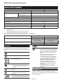
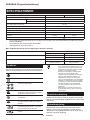
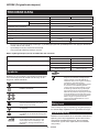
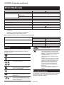
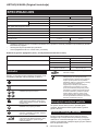
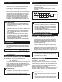
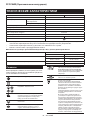
SPECIFICATIONS
Model LS1040 / LS1040S LS1040F / LS1040FS
Blade diameter 255 mm - 260 mm
Hole diameter For all countries other than
European countries
25.4 mm, 25 mm or 30 mm (Country specic)
For European countries 30 mm
Max. kerf thickness of the saw blade 3.2 mm
Max. Miter angle Left 45°, Right 52°
Max. Bevel angle Left 45°
No load speed 5,100 min-1
Dimensions (L x W x H) 530 mm x 476 mm x 532 mm
Net weight 11.8 kg 12.0 kg
Safety class /II
• Due to our continuing program of research and development, the specications herein are subject to change
without notice.
• Specications may dier from country to country.
• Weight according to EPTA-Procedure 01/2014
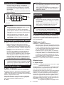
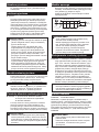
Max. Cutting capacities (H x W) with blade 260 mm in diameter
Bevel angle Miter angle
0° 45° (left and right)
0° 93 mm x 95 mm 93 mm x 67 mm
69 mm x 135 mm 69 mm x 95 mm
45° (left) 53 mm x 95 mm 49 mm x 67 mm
35 mm x 135 mm 35 mm x 94 mm
Symbols
The following show the symbols used for the equip-
ment. Be sure that you understand their meaning before
use.
Read instruction manual.
DOUBLE INSULATION
Wear safety glasses.
To avoid injury from ying debris, keep
holding the saw head down, after making
cuts, until the blade has come to a com-
plete stop.
Do not place hand or ngers close to the
blade.
For your safety, remove the chips, small
pieces, etc. from the table top before
operation.
Always set SUB-FENCE to left position
when performing left bevel cuts. Failure to
do so may cause serious injury to operator.
To loosen the bolt, turn it clockwise.
Only for EU countries
Due to the presence of hazardous compo-
nents in the equipment, used electrical and
electronic equipment may have a negative
impact on the environment and human
health.
Do not dispose of electrical and electronic
appliances with household waste!
In accordance with the European Directive
on waste electrical and electronic equip-
ment and its adaptation to national law,
used electrical and electronic equipment
should be collected separately and
delivered to a separate collection point
for municipal waste, operating in accor-
dance with the environmental protection
regulations.
This is indicated by the symbol of the
crossed-out wheeled bin placed on the
equipment.
Intended use
The tool is intended for accurate straight and miter
cutting in wood. With appropriate saw blades, aluminum
can also be sawed.

9ENGLISH
Power supply
The tool should be connected only to a power supply of
the same voltage as indicated on the nameplate, and
can only be operated on single-phase AC supply. They
are double-insulated and can, therefore, also be used
from sockets without earth wire.
For public low-voltage distribution
systems of between 220 V and 250 V
For Model LS1040
Switching operations of electric apparatus cause volt-
age uctuations. The operation of this device under
unfavorable mains conditions can have adverse eects
to the operation of other equipment. With a mains
impedance equal or less than 0.29 Ohms it can be pre-
sumed that there will be no negative eects. The mains
socket used for this device must be protected with a
fuse or protective circuit breaker having slow tripping
characteristics.
For Model LS1040F
Switching operations of electric apparatus cause volt-
age uctuations. The operation of this device under
unfavorable mains conditions can have adverse eects
to the operation of other equipment. With a mains
impedance equal or less than 0.34 Ohms it can be pre-
sumed that there will be no negative eects. The mains
socket used for this device must be protected with a
fuse or protective circuit breaker having slow tripping
characteristics.
Noise
The typical A-weighted noise level determined accord-
ing to EN62841-3-9:
Sound pressure level (LpA) : 91 dB(A)
Sound power level (LWA) : 101 dB (A)
Uncertainty (K) : 3 dB(A)
NOTE: The declared noise emission value(s) has
been measured in accordance with a standard test
method and may be used for comparing one tool with
another.
NOTE: The declared noise emission value(s)
may also be used in a preliminary assessment of
exposure.
WARNING: Wear ear protection.
WARNING: The noise emission during actual
use of the power tool can dier from the declared
value(s) depending on the ways in which the
tool is used especially what kind of workpiece is
processed.
WARNING: Be sure to identify safety mea-
sures to protect the operator that are based on an
estimation of exposure in the actual conditions of
use (taking account of all parts of the operating
cycle such as the times when the tool is switched
o and when it is running idle in addition to the
trigger time).
Vibration
The vibration total value (tri-axial vector sum) deter-
mined according to EN62841-3-9:
Vibration emission (ah) : 2.5 m/s2 or less
Uncertainty (K) : 1.5 m/s2
NOTE: The declared vibration total value(s) has been
measured in accordance with a standard test method
and may be used for comparing one tool with another.
NOTE: The declared vibration total value(s) may also
be used in a preliminary assessment of exposure.
WARNING: The vibration emission during
actual use of the power tool can dier from the
declared value(s) depending on the ways in which
the tool is used especially what kind of workpiece
is processed.
WARNING: Be sure to identify safety mea-
sures to protect the operator that are based on an
estimation of exposure in the actual conditions of
use (taking account of all parts of the operating
cycle such as the times when the tool is switched
o and when it is running idle in addition to the
trigger time).
EC Declaration of Conformity
For European countries only
The EC declaration of conformity is included as Annex A
to this instruction manual.
General power tool safety warnings
WARNING: Read all safety warnings, instruc-
tions, illustrations and specications provided
with this power tool. Failure to follow all instructions
listed below may result in electric shock, re and/or
serious injury.
Save all warnings and instruc-
tions for future reference.
The term "power tool" in the warnings refers to your
mains-operated (corded) power tool or battery-operated
(cordless) power tool.
Safety instructions for mitre saws
1. Mitre saws are intended to cut wood or wood-
like products, they cannot be used with abra-
sive cut-o wheels for cutting ferrous material
such as bars, rods, studs, etc. Abrasive dust
causes moving parts such as the lower guard to
jam. Sparks from abrasive cutting will burn the
lower guard, the kerf insert and other plastic parts.
2. Use clamps to support the workpiece when-
ever possible. If supporting the workpiece
by hand, you must always keep your hand at
least 100 mm from either side of the saw blade.
Do not use this saw to cut pieces that are too
small to be securely clamped or held by hand.
If your hand is placed too close to the saw blade,
there is an increased risk of injury from blade
contact.

10 ENGLISH
3. The workpiece must be stationary and
clamped or held against both the fence and the
table. Do not feed the workpiece into the blade
or cut "freehand" in any way. Unrestrained
or moving workpieces could be thrown at high
speeds, causing injury.
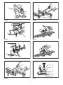
4. Never cross your hand over the intended line
of cutting either in front or behind the saw
blade. Supporting the workpiece "cross handed"
i.e. holding the workpiece to the right of the saw
blade with your left hand or vice versa is very
dangerous.
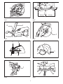
► Fig.1
5. Do not reach behind the fence with either hand
closer than 100 mm from either side of the saw
blade, to remove wood scraps, or for any other
reason while the blade is spinning. The proxim-
ity of the spinning saw blade to your hand may not
be obvious and you may be seriously injured.
6. Inspect your workpiece before cutting. If the
workpiece is bowed or warped, clamp it with
the outside bowed face toward the fence.
Always make certain that there is no gap
between the workpiece, fence and table along
the line of the cut. Bent or warped workpieces
can twist or shift and may cause binding on the
spinning saw blade while cutting. There should be
no nails or foreign objects in the workpiece.
7. Do not use the saw until the table is clear of all
tools, wood scraps, etc., except for the work-
piece. Small debris or loose pieces of wood or
other objects that contact the revolving blade can
be thrown with high speed.
8. Cut only one workpiece at a time. Stacked multi-
ple workpieces cannot be adequately clamped or
braced and may bind on the blade or shift during
cutting.
9. Ensure the mitre saw is mounted or placed on
a level, rm work surface before use. A level
and rm work surface reduces the risk of the mitre
saw becoming unstable.
10. Plan your work. Every time you change the
bevel or mitre angle setting, make sure the
adjustable fence is set correctly to support the
workpiece and will not interfere with the blade
or the guarding system. Without turning the tool
"ON" and with no workpiece on the table, move
the saw blade through a complete simulated cut to
assure there will be no interference or danger of
cutting the fence.
11. Provide adequate support such as table exten-
sions, saw horses, etc. for a workpiece that is
wider or longer than the table top. Workpieces
longer or wider than the mitre saw table can tip
if not securely supported. If the cut-o piece or
workpiece tips, it can lift the lower guard or be
thrown by the spinning blade.
12. Do not use another person as a substitute for
a table extension or as additional support.
Unstable support for the workpiece can cause the
blade to bind or the workpiece to shift during the
cutting operation pulling you and the helper into
the spinning blade.
13. The cut-o piece must not be jammed or
pressed by any means against the spinning
saw blade. If conned, i.e. using length stops, the
cut-o piece could get wedged against the blade
and thrown violently.
14. Always use a clamp or a xture designed to
properly support round material such as rods
or tubing. Rods have a tendency to roll while
being cut, causing the blade to "bite" and pull the
work with your hand into the blade.
15. Let the blade reach full speed before contact-
ing the workpiece. This will reduce the risk of the
workpiece being thrown.
16. If the workpiece or blade becomes jammed,
turn the mitre saw o. Wait for all moving
parts to stop and disconnect the plug from
the power source and/or remove the battery
pack. Then work to free the jammed material.
Continued sawing with a jammed workpiece could
cause loss of control or damage to the mitre saw.
17. After nishing the cut, release the switch,
hold the saw head down and wait for the blade
to stop before removing the cut-o piece.
Reaching with your hand near the coasting blade
is dangerous.
18. Hold the handle rmly when making an incom-
plete cut or when releasing the switch before
the saw head is completely in the down posi-
tion. The braking action of the saw may cause
the saw head to be suddenly pulled downward,
causing a risk of injury.
19. Only use the saw blade with the diameter that
is marked on the tool or specied in the man-
ual. Use of an incorrectly sized blade may aect
the proper guarding of the blade or guard opera-
tion which could result in serious personal injury.
20. Only use the saw blades that are marked with
a speed equal or higher than the speed marked
on the tool.
21. Do not use the saw to cut other than wood,
aluminum or similar materials.
22. (For European countries only)
Always use the blade which conforms to
EN847-1.
Additional instructions
1. Make workshop kid proof with padlocks.
2. Never stand on the tool. Serious injury could
occur if the tool is tipped or if the cutting tool is
unintentionally contacted.
3. Never leave the tool running unattended. Turn
the power o. Do not leave tool until it comes
to a complete stop.
4. Do not operate saw without guards in place.
Check blade guard for proper closing before
each use. Do not operate saw if blade guard
does not move freely and close instantly.
Never clamp or tie the blade guard into the
open position.
5. Keep hands out of path of saw blade. Avoid
contact with any coasting blade. It can still
cause severe injury.

11 ENGLISH
6. Always secure all moving portions before
carrying the tool.
7. Stopper pin which locks the cutter head down
is for carrying and storage purposes only and
not for any cutting operations.
8. Check the blade carefully for cracks or dam-
age before operation. Replace cracked or dam-
aged blade immediately. Gum and wood pitch
hardened on blades slows saw and increases
potential for kickback. Keep blade clean by
rst removing it from tool, then cleaning it with
gum and pitch remover, hot water or kerosene.
Never use gasoline to clean blade.
9. Use only anges specied for this tool.
10. Be careful not to damage the arbor, anges
(especially the installing surface) or bolt.
Damage to these parts could result in blade
breakage.
11. Make sure that the turn base is properly
secured so it will not move during operation.
Use the holes in the base to fasten the saw to a
stable work platform or bench. NEVER use tool
where operator positioning would be awkward.
12. Make sure the shaft lock is released before the
switch is turned on.
13. Be sure that the blade does not contact the
turn base in the lowest position.
14. Hold the handle rmly. Be aware that the saw
moves up or down slightly during start-up and
stopping.
15. Make sure the blade is not contacting the
workpiece before the switch is turned on.
16. Before using the tool on an actual workpiece,
let it run for a while. Watch for vibration or
wobbling that could indicate poor installation
or a poorly balanced blade.
17. Stop operation immediately if you notice any-
thing abnormal.
18. Do not attempt to lock the trigger in the "ON"
position.
19. Always use accessories recommended in this
manual. Use of improper accessories such as
abrasive wheels may cause an injury.
20. Some material contains chemicals which may
be toxic. Take caution to prevent dust inhala-
tion and skin contact. Follow material supplier
safety data.
Additional safety rules for the laser
1. LASER RADIATION, DO NOT STARE INTO THE
BEAM OR VIEW DIRECTLY WITH OPTICAL
INSTRUMENTS, CLASS 2M LASER PRODUCT.
SAVE THESE INSTRUCTIONS.
WARNING: DO NOT let comfort or familiarity
with product (gained from repeated use) replace
strict adherence to safety rules for the subject
product. MISUSE or failure to follow the safety
rules stated in this instruction manual may cause
serious personal injury.
INSTALLATION
Installing auxiliary plate
► Fig.2: 1. Auxiliary plate 2. Hex bolt 3. Base
► Fig.3: 1. Auxiliary plate 2. Base 3. Hex bolt 4. Nut
Installing the auxiliary plate using the notch in the tool's
base and secure it by tightening the hex bolt.
Bench mounting
When the tool is shipped, the handle is locked in the low-
ered position by the stopper pin. Release the stopper pin by
lowering the handle slightly and pulling the stopper pin.
► Fig.4: 1. Stopper pin
This tool should be bolted with two bolts to a level and sta-
ble surface using the bolt holes provided in the tool's base.
This will help prevent tipping and possible personal injury.
► Fig.5: 1. Bolt
FUNCTIONAL DESCRIPTION
CAUTION:
• Always be sure that the tool is switched o and
unplugged before adjusting or checking function
on the tool.
Blade guard
► Fig.6: 1. Blade guard
When lowering the handle, the blade guard rises automat-
ically. The guard is spring loaded so it returns to its original
position when the cut is completed and the handle is raised.
NEVER DEFEAT OR REMOVE THE BLADE GUARD OR
THE SPRING WHICH ATTACHES TO THE GUARD.
In the interest of your personal safety, always maintain
the blade guard in good condition. Any irregular opera-
tion of the blade guard should be corrected immediately.
Check to assure spring loaded return action of guard.
NEVER USE THE TOOL IF THE BLADE GUARD OR
SPRING ARE DAMAGED, FAULTY OR REMOVED.
DOING SO IS HIGHLY DANGEROUS AND CAN
CAUSE SERIOUS PERSONAL INJURY.
If the see-through blade guard becomes dirty, or saw-
dust adheres to it in such a way that the blade is no lon-
ger easily visible, unplug the saw and clean the guard
carefully with a damp cloth. Do not use solvents or any
petroleum-based cleaners on the plastic guard.
If the blade guard is especially dirty and vision through
the guard is impaired, use the supplied socket wrench
to loosen the hex bolt holding the center cover. Loosen
the hex bolt by turning it counterclockwise and raise
the blade guard and center cover. With the blade guard
so positioned, cleaning can be more completely and
eciently accomplished. When cleaning is complete,
reverse procedure above and secure bolt. Do not
remove spring holding blade guard. If guard becomes
discolored through age or UV light exposure, contact
a Makita service center for a new guard. DO NOT
DEFEAT OR REMOVE GUARD.
► Fig.7: 1. Blade guard

12 ENGLISH
Kerf board
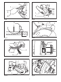
► Fig.8: 1. Kerf board 2. Turn base
This tool is provided with the kerf board in the turn base
to minimize tearing on the exit side of a cut. If the kerf
groove has not yet been cut in the kerf board by the
factory, you should cut the groove before actually using
the tool to cut a workpiece. Switch on the tool and lower
the blade gently to cut a groove in the kerf board.
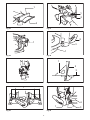
Maintaining maximum cutting capacity
► Fig.9: 1. Socket wrench 2. Adjusting bolt
► Fig.10: 1. Top surface of turn base 2. Periphery of
blade 3. Guide fence
This tool is factory adjusted to provide the maximum
cutting capacity for a 260 mm saw blade.
When installing a new blade, always check the lower limit
position of the blade and if necessary, adjust it as follows:
First, unplug the tool. Lower the handle completely. Use
the socket wrench to turn the adjusting bolt until the
periphery of the blade extends slightly below the top
surface of the turn base at the point where the front face
of the guide fence meets the top surface of the turn base.
With the tool unplugged, rotate the blade by hand while
holding the handle all the way down to be sure that
the blade does not contact any part of the lower base.
Re-adjust slightly, if necessary.
CAUTION:
• After installing a new blade, always be sure that
the blade does not contact any part of the lower
base when the handle is lowered completely.
Always do this with the tool unplugged.
Adjusting the miter angle
► Fig.11:
1. Pointer 2. Lock lever 3. Grip 4. Miter scale
Loosen the grip by turning counterclockwise. Turn the turn base
while pressing down the lock lever. When you have moved the
grip to the position where the pointer points to the desired angle
on the miter scale, securely tighten the grip clockwise.
CAUTION:
• When turning the turn base, be sure to raise the
handle fully.
• After changing the miter angle, always secure
the turn base by tightening the grip rmly.
Adjusting the bevel angle
► Fig.12: 1. Lever
► Fig.13: 1. Lever 2. Bevel scale 3. Pointer
To adjust the bevel angle, loosen the lever at the rear of
the tool counterclockwise.
Push the handle to the left to tilt the saw blade until the
pointer points to the desired angle on the bevel scale.
Then tighten the lever clockwise rmly to secure the arm.
CAUTION:
• When tilting the saw blade, be sure to raise the
handle fully.
• After changing the bevel angle, always secure
the arm by tightening the lever clockwise.
Switch action
WARNING: Before plugging in the tool,
always check to see that the switch trigger actu-
ates properly and returns to the "OFF" position
when released. Do not pull the switch trigger hard
without pressing in the lock-o button. This can
cause switch breakage. Operating a tool with a
switch that does not actuate properly can lead to loss
of control and serious personal injury.
WARNING: NEVER use tool without a fully
operative switch trigger. Any tool with an inoper-
ative switch is HIGHLY DANGEROUS and must be
repaired before further usage or serious personal
injury may occur.
WARNING: NEVER defeat the lock-o button
by taping down or some other means. A switch with
a negated lock-o button may result in unintentional
operation and serious personal injury.
WARNING: NEVER use the tool if it runs when
you simply pull the switch trigger without press-
ing the lock-o button. A switch in need of repair
may result in unintentional operation and serious
personal injury. Return tool to a Makita service center
for proper repairs BEFORE further usage.
► Fig.14: 1. Switch trigger 2. Lock-o button 3. Hole
for padlock
To prevent the switch trigger from being accidentally
pulled, a lock-o button is provided. To start the tool,
press in the lock-o button and pull the switch trigger.
Release the switch trigger to stop.
A hole is provided in the switch trigger for insertion of a
padlock to lock the tool o.
WARNING: Do not use a lock with a shank
or cable any smaller than 6.35 mm in diameter. A
smaller shank or cable may not properly lock the tool
in the o position and unintentional operation may
occur resulting in serious personal injury.
Lighting up the lamps
Only for model LS1040F / LS1040FS
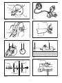
► Fig.15: 1. Light switch
CAUTION:
• This is not a rainproof light. Do not wash the
light in water or use it in a rain or a wet area.
Such a conduct can cause an electric shock and
fume.
• Do not touch the lens of the light, as it is very hot
while it is lighted or shortly after it is turned o.
This may cause a burn to a human body.
• Do not apply impact to the light, which may
cause damage or shorted service time to it.
• Do not keep casting the beam of the light to your
eyes. This can cause your eyes to be hurt.
• Do not cover the light with clothes, carton, card-
board or similar objects while it is lighted, which
can cause a re or an ignition.

13 ENGLISH
Push the upper position of the switch for turning on the
light and the lower position for o.
Move the light to shift an area of lighting.
► Fig.16: 1. Light 2. Light switch
NOTE:
• Use a dry cloth to wipe the dirt o the lens of
lamp. Be careful not to scratch the lens of light,
or it may lower the illumination.
ASSEMBLY
CAUTION:
• Always be sure that the tool is switched o and
unplugged before carrying out any work on the
tool.
Installing or removing saw blade
CAUTION: Always be sure that the tool is
switched o and unplugged before installing or
removing the blade.
CAUTION:
Use only the Makita socket wrench
provided to install or remove the blade. Failure to do
so may result in overtightening or insucient tighten-
ing of the hex bolt. This could cause an injury.
When removing or installing the blade, keep the handle
in the raised position.
To remove the blade, use the socket wrench to loosen
the hex bolt holding the center cover by turning it coun-
terclockwise. Raise the blade guard and center cover.
► Fig.17: 1. Center cover 2. Socket wrench 3. Hex
bolt 4. Blade guard
Press the shaft lock to lock the spindle and use the
wrench to loosen the hex bolt clockwise. Then remove
the hex bolt, outer ange and blade.
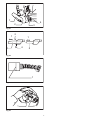
► Fig.18: 1. Socket wrench 2. Shaft lock
To install the blade, mount it carefully onto the spindle, making
sure that the direction of the arrow on the surface of the blade
matches the direction of the arrow on the blade case.
► Fig.19:
1. Blade case 2. Arrow 3. Saw blade 4. Arrow
Install the ange and hex bolt, and then use the socket
wrench to tighten the hex bolt (left-handed) securely
counterclockwise while pressing the shaft lock.
► Fig.20: 1. Spindle 2. Flange 3. Saw blade 4. Flange
5. Hex bolt 6. Ring
CAUTION: The ring 25.4 mm or 30 mm in
outer diameter is factory-installed onto the spin-
dle. Before mounting the blade onto the spindle,
always be sure that the correct ring for the arbor
hole of the blade you intend to use is installed
onto the spindle.
Return the blade guard and center cover to its original
position. Then tighten the hex bolt clockwise to secure
the center cover. Lower the handle to make sure that
the blade guard moves properly. Make sure shaft lock
has released spindle before making cut.
Connecting a vacuum cleaner
When you wish to perform clean cutting operation,
connect a Makita vacuum cleaner.
► Fig.21
Dust bag
► Fig.22: 1. Dust nozzle 2. Dust bag 3. Fastener
The use of the dust bag makes cutting operations clean
and dust collection easy. To attach the dust bag, t it
onto the dust nozzle.
When the dust bag is about half full, remove the dust
bag from the tool and pull the fastener out. Empty
the dust bag of its contents, tapping it lightly so as to
remove particles adhering to the insides which might
hamper further collection.
Securing workpiece
WARNING:
• It is extremely important to always secure the
workpiece properly and tightly with the vise.
Failure to do so can cause the tool to be dam-
aged and/or the workpiece to be destroyed.
PERSONAL INJURY MAY ALSO RESULT. Also,
after a cutting operation, DO NOT raise the
blade until the blade has come to a complete
stop.
CAUTION:
• When cutting long workpieces, use supports
that are as high as the top surface level of the
turn base. Do not rely solely on the vertical vise
and/or horizontal vise to secure the workpiece.
Thin material tends to sag. Support workpiece
over its entire length to avoid blade pinch and
possible KICKBACK.
► Fig.23: 1. Support 2. Turn base
Sub-fence
► Fig.24: 1. Sub-fence
This tool is equipped with the sub-fence. It should be
positioned as shown in the gure.
CAUTION:
• When performing left bevel cuts, ip the fence
over to the left position as shown in the gure.
Otherwise, it will contact the blade or a part of
the tool, causing possible serious injury to the
operator.
► Fig.25: 1. Sub-fence

14 ENGLISH
Vertical vise
► Fig.26: 1. Vise arm 2. Vise rod 3. Guide fence
4. Holder 5. Holder assembly 6. Vise knob
7. Screw
The vertical vise can be installed in two positions on
either the left or right side of the guide fence or the
holder assembly (optional accessory). Insert the vise
rod into the hole in the guide fence or the holder assem-
bly and tighten the screw to secure the vise rod.
Position the vise arm according to the thickness and
shape of the workpiece and secure the vise arm by
tightening the screw. If the screw to secure the vise arm
contacts the guide fence, install the screw on the oppo-
site side of vise arm. Make sure that no part of the tool
contacts the vise when lowering the handle all the way.
If some part contacts the vise, re-position the vise.
Press the workpiece at against the guide fence and the
turn base. Position the workpiece at the desired cutting
position and secure it rmly by tightening the vise knob.
CAUTION:
• The workpiece must be secured rmly against
the turn base and guide fence with the vise
during all operations.
Horizontal vise (optional accessory)
► Fig.27: 1. Vise knob 2. Projection 3. Vise shaft
4. Base
The horizontal vise can be installed on either the left or
right side of the base. When performing 15° or greater
miter cuts, install the horizontal vise on the side oppo-
site the direction in which the turn base is to be turned.
By turning the vise knob counterclockwise, the screw
is released and the vise shaft can be moved rapidly in
and out. By turning the vise knob clockwise, the screw
remains secured. To grip the workpiece, turn the vise
knob gently clockwise until the projection reaches its
topmost position, then fasten securely. If the vise knob
is forced in or pulled out while being turned clockwise,
the projection may stop at an angle. In this case, turn
the vise knob back counterclockwise until the screw is
released, before turning again gently clockwise.
The maximum width of the workpiece which can be
secured by the horizontal vise is 130 mm.
CAUTION:
• Grip the workpiece only when the projection is
at the topmost position. Failure to do so may
result in insucient securing of the workpiece.
This could cause the workpiece to be thrown,
cause damage to the blade or cause the loss
of control, which can result in PERSONAL
INJURY.
Holders and holder assembly
(optional accessories)
► Fig.28: 1. Holder 2. Holder assembly
The holders and the holder assembly can be installed
on either side as a convenient means of supporting
workpieces horizontally. Install them as shown in the
gure. Then tighten the screws rmly to secure the
holders and the holder assembly.
When cutting long workpieces, use the holder-rod
assembly (optional accessory). It consists of two holder
assemblies and two rods 12.
► Fig.29: 1. Holder assembly 2. Rod 12
CAUTION:
• Always support long workpieces level with the
top surface of the turn base for accurate cuts
and to prevent dangerous loss of control of the
tool.
OPERATION
CAUTION:
• Before use, be sure to release the handle from
the lowered position by pulling the stopper pin.
• Make sure the blade is not contacting the work-
piece, etc. before the switch is turned on.
• Do not apply excessive pressure on the handle
when cutting. Too much force may result in
overload of the motor and/or decreased cutting
eciency. Push down handle with only as much
force as is necessary for smooth cutting and
without signicant decrease in blade speed.
• Gently press down the handle to perform the
cut. If the handle is pressed down with force or if
lateral force is applied, the blade will vibrate and
leave a mark (saw mark) in the workpiece and
the precision of the cut will be impaired.
• Do not release the saw head uncontrolled from
the fully down position. Uncontrolled saw head
may hit you and it will result in personal injury.
Press cutting
► Fig.30
Secure the workpiece with the vise. Switch on the
tool without the blade making any contact and wait
until the blade attains full speed before lowering.
Then gently lower the handle to the fully lowered
position to cut the workpiece. When the cut is
completed, switch o the tool and WAIT UNTIL
THE BLADE HAS COME TO A COMPLETE STOP
before returning the blade to its fully elevated
position.
Miter cutting
Refer to the previously covered "Adjusting the
miter angle".

15 ENGLISH
Bevel cut
► Fig.31
Loosen the lever and tilt the saw blade to set
the bevel angle (Refer to the previously covered
"Adjusting the bevel angle"). Be sure to retighten
the lever rmly to secure the selected bevel angle
safely. Secure the workpiece with a vise. Switch
on the tool without the blade making any contact
and wait until the blade attains full speed. Then
gently lower the handle to the fully lowered posi-
tion while applying pressure in parallel with the
blade. When the cut is completed, switch o the
tool and WAIT UNTIL THE BLADE HAS COME TO
A COMPLETE STOP before returning the blade to
its fully elevated position.
CAUTION:
• Always be sure that the blade will move down to
bevel direction during a bevel cut. Keep hands
out of path of saw blade.
• During a bevel cut, it may create a condition
whereby the piece cut o will come to rest
against the side of the blade. If the blade is
raised while the blade is still rotating, this piece
may be caught by the blade, causing fragments
to be scattered which is dangerous. The blade
should be raised ONLY after the blade has
come to a complete stop.
• When pressing the handle down, apply pressure
parallel to the blade. If the pressure is not par-
allel to the blade during a cut, the angle of the
blade might be shifted and the precision of the
cut will be impaired.
• Always set the sub-fence to the left position
when performing left bevel cuts.
Compound cutting
Compound cutting is the process in which a bevel
angle is made at the same time in which a miter
angle is being cut on a workpiece. Compound cut-
ting can be performed at angle shown in the table.
Miter angle
Bevel angle
Left and Right 0 - 45
45
When performing compound cutting, refer to
"Press cutting", "Miter cutting" and "Bevel cut"
explanations.
Cutting aluminum extrusion
► Fig.32: 1. Vise 2. Spacer block 3. Guide fence
4. Aluminum extrusion 5. Spacer block
When securing aluminum extrusions, use spacer
blocks or pieces of scrap as shown in the gure to
prevent deformation of the aluminum. Use a cutting
lubricant when cutting the aluminum extrusion to pre-
vent build-up of the aluminum material on the blade.
CAUTION:
• Never attempt to cut thick or round aluminum
extrusions. Thick aluminum extrusions may
come loose during operation and round alumi-
num extrusions cannot be secured rmly with
this tool.
Wood facing
Use of wood facing helps to assure splinter-free
cuts in workpieces. Attach a wood facing to the
guide fence using the holes in the guide fence.
See the gure concerning the dimensions for a
suggested wood facing.
Over 10mm (3/8") Over 460mm (18-1/8")
11
90mm
(3-9/16")
25mm
(1")
90mm
(3-9/16")
107mm
(4-7/32")
90mm
(3-9/16")
107mm
(4-7/32")
1. Hole
CAUTION:
• Use straight wood of even thickness as the
wood facing.
• Use screws to attach the wood facing to the
guide fence. The screws should be installed so
that the screw heads are below the surface of
the wood facing.
• When the wood facing is attached, do not turn
the turn base with the handle lowered. The
blade and/or the wood facing will be damaged.
Cutting repetitive lengths
► Fig.33: 1. Set plate 2. Holder 3. Screw
When cutting several pieces of stock to the same
length, ranging from 240 mm to 400 mm, use of
the set plate (optional accessory) will facilitate
more ecient operation. Install the set plate on the
holder (optional accessory) as shown in the gure.
Align the cutting line on your workpiece with either
the left or right side of the groove in the kerf board,
and while holding the workpiece from moving,
move the set plate ush against the end of the
workpiece. Then secure the set plate with the
screw. When the set plate is not used, loosen the
screw and turn the set plate out of the way.
NOTE:
• Use of the holder-rod assembly (optional acces-
sory) allows cutting repetitive lengths up to
2,200 mm (7.2 ft.) approximately.
Carrying tool
► Fig.34: 1. Stopper pin
Make sure that the tool is unplugged. Secure the blade
at 0° bevel angle and the turn base at left miter angle
fully. Lower the handle fully and lock it in the lowered
position by pushing in the stopper pin.
Carry the tool by carrying grip as shown in the gure. If you remove
the holders, dust bag, etc., you can carry the tool more easily.
► Fig.35
CAUTION:
• Always secure all moving portions before carry-
ing the tool.
• Stopper pin is for carrying and storage purposes
only and not for any cutting operations.

16 ENGLISH
MAINTENANCE
CAUTION:
• Always be sure that the tool is switched o and
unplugged before attempting to perform inspec-
tion or maintenance.
• Never use gasoline, benzine, thinner, alcohol
or the like. Discoloration, deformation or cracks
may result.
WARNING:
• Always be sure that the blade is sharp and clean
for the best and safest performance.
Adjusting the cutting angle
This tool is carefully adjusted and aligned at the factory,
but rough handling may have aected the alignment. If
your tool is not aligned properly, perform the following:
Miter angle
► Fig.36: 1. Hex bolt
Loosen the grip which secures the turn base. Turn
the turn base so that the pointer points to 0° on the
miter scale. Tighten the grip and loosen the hex
bolts securing the guide fence using the socket
wrench.
Lower the handle fully and lock it in the lowered
position by pushing in the stopper pin. Square
the side of the blade with the face of the guide
fence using a triangular rule, try-square, etc. Then
securely tighten the hex bolts on the guide fence
in the order from the right side.
► Fig.37: 1. Triangular rule 2. Grip 3. Guide fence
Bevel angle
0° bevel angle
► Fig.38: 1. Turn base 2. Lever 3. 0° adjusting bolt
Lower the handle fully and lock it in the lowered position
by pushing in the stopper pin. Loosen the lever at the
rear of the tool.
Turn the 0° bevel angle adjusting bolt on the right side
of the turn base two or three revolutions clockwise to tilt
the blade to the right.
Carefully square the side of the blade with the top
surface of the turn base using the triangular rule, try-
square, etc. by turning the 0° bevel angle adjusting bolt
counterclockwise. Then tighten the lever securely.
► Fig.39: 1. Triangular rule 2. Saw blade 3. Top sur-
face of turn base
Make sure that the pointer on the turn base point to 0°
on the bevel scale on the arm. If it does not point to 0°,
loosen the screw which secures the pointer and adjust
the pointer so that it will point to 0°.
► Fig.40: 1. Arm 2. Bevel scale 3. Pointer 4. Turn
base
45° bevel angle
► Fig.41: 1. Lever 2. Arm 3. Pointer 4. 45° bevel angle
adjusting bolt
Adjust the 45° bevel angle only after performing 0°
bevel angle adjustment. To adjust left 45° bevel angle,
loosen the lever and tilt the blade to the left fully. Make
sure that the pointer on the arm points to 45° on the
bevel scale on the arm holder. If the pointer does not
point to 45°, turn the 45° bevel angle adjusting bolt on
the left side of the arm until the pointer points to 45°.
Replacing uorescent tube
Only for model LS1040F / LS1040FS
► Fig.42: 1. Pull out 2. Push 3. Lamp box 4. Screws
5. Fluorescent tube
CAUTION:
• Always be sure that the tool is switched o and
unplugged before replacing the uorescent
tube.
• Do not apply force, impact or scratch to a u-
orescent tube, which can cause a glass of the
uorescent tube to be broken resulting in a
injury to you or your bystanders.
• Leave the orescent tube for a while immedi-
ately after a use of it and then replace it. If not.
You may burn yourself.
Remove screws, which secure Lamp Box for the light.
Pull out the Lamp Box keeping pushing lightly the upper
position of it as illustrated on the left.
Pull out the uorescent tube and then replace it with
Makita original new one.
Replacing carbon brushes
► Fig.43: 1. Limit mark
Remove and check the carbon brushes regularly.
Replace when they wear down to the limit mark. Keep
the carbon brushes clean and free to slip in the holders.
Both carbon brushes should be replaced at the same
time. Use only identical carbon brushes.
Use a screwdriver to remove the brush holder caps.
Take out the worn carbon brushes, insert the new ones
and secure the brush holder caps.
► Fig.44: 1. Screwdriver 2. Brush holder cap
After use
• After use, wipe o chips and dust adhering to the
tool with a cloth or the like. Keep the blade guard
clean according to the directions in the previously
covered section titled "Blade guard". Lubricate the
sliding portions with machine oil to prevent rust.
To maintain product SAFETY and RELIABILITY, repairs,
any other maintenance or adjustment should be per-
formed by Makita Authorized Service Centers, always
using Makita replacement parts.

17 ENGLISH
OPTIONAL
ACCESSORIES
WARNING: These Makita accessories or
attachments are recommended for use with your
Makita tool specied in this manual. The use of
any other accessories or attachments may result in
serious personal injury.
WARNING: Only use the Makita accessory
or attachment for its stated purpose. Misuse of
an accessory or attachment may result in serious
personal injury.
If you need any assistance for more details regard-
ing these accessories, ask your local Makita Service
Center.
• Steel & Carbide-tipped saw blade
(Refer to our website or contact your local Makita
dealer for the correct saw blades to be used for
the material to be cut.)
• Auxiliary plate
• Vise assembly (Horizontal vise)
• Vertical vise
• Socket wrench
• Holder set
• Holder assembly
• Holder rod assembly
• Set plate
• Dust bag
• Triangular rule
• Fluorescent tube
NOTE:
• Some items in the list may be included in the
tool package as standard accessories. They
may dier from country to country.

18 SVENSKA
SVENSKA (Originalinstruktioner)
SPECIFIKATIONER
Modell LS1040 / LS1040S LS1040F / LS1040FS
Klingdiameter 255 mm - 260 mm
Håldiameter För alla länder utanför Europa 25,4 mm, 25 mm eller 30 mm (landsspecikt)
För länder i Europa 30 mm
Max skärtjocklek på sågklingan 3,2 mm
Max. geringsvinkel Vänster 45°, höger 52°
Max. för vinkelsågning Vänster 45°
Hastighet utan belastning 5 100 min-1
Dimensioner (L x B x H) 530 mm x 476 mm x 532 mm
Nettovikt 11,8 kg 12,0 kg
Säkerhetsklass /II
• På grund av vårt pågående program för forskning och utveckling kan dessa specikationer ändras utan föregå-
ende meddelande.
• Specikationer kan variera mellan olika länder.
• Vikt enligt EPTA-procedur 01/2014
Max. sågkapacitet (H x B) med en sågklinga på 260 mm i diameter
Vinkel för vinkelsågning Geringsvinkel
0° 45° (vänster och höger)
0° 93 mm x 95 mm 93 mm x 67 mm
69 mm x 135 mm 69 mm x 95 mm
45° (vänster) 53 mm x 95 mm 49 mm x 67 mm
35 mm x 135 mm 35 mm x 94 mm
Symboler
Följande visar symbolerna som används för utrustningen. Se
till att du förstår innebörden innan du använder borrmaskinen.
Läs bruksanvisningen.
DUBBEL ISOLERING
Använd skyddsglasögon.
Undvik skador från ygande materialrester,
fortsätt efter sågning att hålla ned såghuvu-
det tills bladet har stannat helt.
Håll inte handen eller ngrarna i närheten
av sågbladet.
Avlägsna av säkerhetsskäl spån, småbitar
etc. från bordets översida innan arbetet
påbörjas.
Ställ alltid STÖDANHÅLLET i vänsterläget
vid vinkelsågning åt vänster. I annat fall
kan användaren skadas allvarligt.
Lossa bulten genom att skruva den
medurs.
Gäller endast inom EU
P.g.a. förekomsten av farliga komponenter
i utrustningen kan begagnad elektrisk och
elektronisk utrustning ha negativ inverkan
på miljön och människors hälsa.
Kassera inte elektriska och elektroniska
apparater ihop med hushållsavfall!
I enlighet med EU-direktivet om avfall som
utgörs av eller innehåller elektrisk och
elektronisk utrustning, och dess införli-
vande i nationell lagstiftning, bör begagnad
elektrisk och elektronisk utrustning samlas
in separat och transporteras till en särskild
uppsamlingsplats för kommunalt avfall,
som drivs i enlighet med regelverket för
miljöskydd.
Detta anges av symbolen med den över-
kryssade soptunnan på hjul som sitter på
utrustningen.
Avsedd användning
Maskinen är avsedd för exakt rak sågning och gerings-
sågning i trä. Med lämpliga sågblad kan man även såga
i aluminium.
Strömförsörjning
Maskinen får endast anslutas till elnät med samma
spänning som anges på typplåten och med enfasig
växelström. De är dubbelisolerade och får därför också
anslutas i ojordade vägguttag.

19 SVENSKA
Avsedd för elnät med 220-250 V
För modell LS1040
Att starta och stänga av elektriska apparater medför spänningsvaria-
tioner. Om denna maskin används under ogynnsamma nätspännings-
förhållanden kan funktioner hos annan utrustning påverkas negativt.
I elnät med ett motstånd på högst 0,29 Ohm är det rimligt att anta att
negativa eekter inte förekommer. Nätuttaget för den här enheten
måste vara försett med trög säkring eller skyddsbrytare.
För modell LS1040F
Att starta och stänga av elektriska apparater medför spänningsva-
riationer. Om denna maskin används under ogynnsamma nätspän-
ningsförhållanden kan funktioner hos annan utrustning påverkas
negativt. I elnät med ett motstånd på högst 0,34 Ohm är det rimligt
att anta att negativa eekter inte förekommer. Nätuttaget för den här
enheten måste vara försett med trög säkring eller skyddsbrytare.
Buller
Den normala bullernivån för A-belastning är bestämd
enligt EN62841-3-9:
Ljudtrycksnivå (LpA) : 91 dB (A)
Ljudeektnivå (LWA) : 101 dB (A)
Mättolerans (K): 3 dB (A)
OBS: Det deklarerade bullervärdet har uppmätts i
enlighet med standardtestmetoden och kan användas
för jämförandet av en maskin med en annan.
OBS: Det deklarerade bulleremissionsvärdet kan
också användas i en preliminär bedömning av expo-
nering för vibration.
VARNING: Använd hörselskydd.
VARNING: Bulleremissionen under faktisk
användning av maskinen kan skilja sig från det
deklarerade värdet, beroende på hur maskinen
används och särskilt vilken typ av arbetsstycke
som behandlas.
VARNING: Var noga med att identiera säker-
hetsåtgärder för att skydda användaren, vilka är
grundade på en uppskattning av graden av expo-
nering för vibrationer under de faktiska använd-
ningsförhållandena, (ta, förutom avtryckartiden,
med alla delar av användarcykeln i beräkningen,
som till exempel tiden då maskinen är avstängd
och när den går på tomgång).
Vibration
Det totala vibrationsvärdet (treaxlad vektorsumma)
bestämt enligt EN62841-3-9:
Vibrationsemission (ah) : 2,5 m/s2 eller lägre
Mättolerans (K): 1,5 m/s2
OBS: Det deklarerade totala vibrationsvärdet har
uppmätts i enlighet med standardtestmetoden och
kan användas för jämförandet av en maskin med en
annan.
OBS: Det deklarerade totala vibrationsvärdet kan
också användas i en preliminär bedömning av expo-
nering för vibration.
VARNING: Vibrationsemissionen under fak-
tisk användning av maskinen kan skilja sig från
det deklarerade värdet, beroende på hur maski-
nen används och särskilt vilken typ av arbetss-
tycke som behandlas.
VARNING: Var noga med att identiera säker-
hetsåtgärder för att skydda användaren, vilka är
grundade på en uppskattning av graden av expo-
nering för vibrationer under de faktiska använd-
ningsförhållandena, (ta, förutom avtryckartiden,
med alla delar av användarcykeln i beräkningen,
som till exempel tiden då maskinen är avstängd
och när den går på tomgång).
EG-försäkran om överensstämmelse
Gäller endast inom EU
EG-försäkran om överensstämmelse inkluderas som
bilaga A till denna bruksanvisning.
Allmänna säkerhetsvarningar för
maskiner
VARNING: Läs alla säkerhetsvarningar, anvis-
ningar, illustrationer och specikationer som
medföljer det här maskinen. Underlåtenhet att följa
instruktionerna kan leda till elstötar, brand och/eller
allvarliga personskador.
Spara alla varningar och instruk-
tioner för framtida referens.
Termen ”maskin” som anges i varningarna hänvisar till din eld-
rivna maskin (sladdansluten) eller batteridrivna maskin (sladdlös).
Säkerhetsinstruktioner för geringssågar
1. Geringssågar är avsedda för att såga i trä eller
träliknande material. De får inte användas med
kapskivor för att kapa stål som stänger, arme-
ringsjärn, nitar etc. Abrasivt damm gör så att rör-
liga delar som det nedre skyddets fastnar. Gnistor
från abrasivt kapande kommer att bränna det
nedre skyddet, skärinsatsen och andra plastdelar.
2.
Använd klämmor när det är möjligt för att stödja
arbetsstycket. Om du håller arbetsstycket med
händerna måste du alltid dem minst 100 mm från
sågklingan. Använd inte denna såg för att såga
ut bitar som är för små för att kunna klämmas
fast ordentligt eller hållas säkert för hand. Om
din hand är placerad för nära sågklingan nns det en
ökad risk för skada från kontakt med klingan.
3. Arbetsstycket måste vara stationärt och
fastklämt eller hållas mot både anhållet och
bordet. Mata inte in arbetsstycket i klingan
eller kapa på ”fri hand” på något sätt. Lösa
eller rörliga arbetsstycken kan slungas ut med hög
hastighet och orsaka skada.
4. För aldrig händerna över den avsedda kaplin-
jen, varken framför eller bakom sågklingan. Att
stödja arbetsstycket ”korsvis” t.ex. genom att hålla
arbetstycket på höger sida med din vänstra hand
eller vice versa är väldigt farligt.
► Fig.1

20 SVENSKA
5. Sträck inte in händerna bakom anhållet närmre
än 100 mm på vardera sidan av sågklingan,
varken för att ta bort trärester eller för några
andra orsaker när klingan snurrar. Närheten
från den roterande sågklingan och din hand
kanske inte är uppenbar och du kan skada dig
allvarligt.
6. Inspektera arbetsstycket innan kapning. Om
arbetsstycket är böjt eller vridet, spänn fast
det med den böjda sidan mot anhållet. Se alltid
till att det inte nns något mellanrum mellan
arbetsstycket, anhållet och bordet utmed
såglinjen. Böjda eller vrängda arbetsstycken kan
vrida sig eller yttas och göra så att den roterande
sågklingan fastnar när du kapar. Det får inte nnas
spikar eller främmande föremål i arbetsstycket.
7. Använd inte sågen innan bordet är fritt från
alla verktyg, träbitar mm., förutom arbetss-
tycket. Små föremål eller lösa träbitar eller andra
föremål som kommer i kontakt med den roterande
klingan kan slungas iväg med hög hastighet.
8. Kapa endast ett arbetsstycke i taget. Flera
arbetsstycken staplade på varandra kan inte
klämmas fast/stöttas ordentligt och kan göra så att
klingan fastnar eller yttas vid kapning.
9. Se till att geringssågen är monterad eller
placerad på en plan, stabil arbetsyta innan
användning. En plan och stabil arbetsyta minskar
risken för att girsågen blir ostabil.
10. Planera ditt arbete. Varje gång du ändrar
inställning på vinkeln eller geringssågen, se till
att det justerbara anhållet är ordentligt inställt
för att stödja arbetsstycket och inte stör med
klingan eller skyddssystemet. Utan att ställa
verktyget i läge ”PÅ” och utan arbetsstycke på
bordet, förytta sågklingan en komplett simulerad
kapning för att säkerställa att inte anhållet stör
eller risk föreligger att du sågar i det.
11. Applicera tillräckligt med stöd, som bords-
förlängning, sågbock etc. för arbetsstycken
som är längre eller bredare än bordsskivan.
Arbetsstycken som är längre eller bredare än
geringssågens bord kan välta om de inte stöds
ordentligt. Om den kapade delen eller arbetss-
tycket välter kan de lyfta det nedre skyddet eller
slungas ut av den roterande klingan.
12. Använd inte en annan person som ersättning
för en bordsförlängning eller som extra stöd.
Ostabilt stöd för arbetsstycket kan göra så att
klingan fastnar eller så att arbetsstycket yttas vid
kapning, vilket kan dra både dig och den assiste-
rande personen in i den roterande klingan.
13. Den kapade delen får inte fastna eller tryckas
mot den roterande sågklingan på något sätt.
Om den begränsas, t.ex. med längdstopp, kan
den kapade delen fastna mot klingan och slungas
kraftigt.
14. Använd alltid en klämma eller skruvtving
avsedd att korrekt stödja runda material som
stänger eller rör. Stänger har en tendens att rulla
när de kapas vilket får bladet att ”bita” och dra
arbetsstycket med din hand in i klingan.
15. Låt klingan uppnå full hastighet innan den
kommer i kontakt med arbetsstycket. Detta
minskar risken för att arbetsstycket slungas iväg.
16. Om arbetsstycket eller klingan fastnar, stäng
av geringssågen. Vänta tills alla rörliga delar
stannat och koppla från kontakten från ström-
källan och/eller ta bort batteripaketet. Därefter
kan du avlägsna det material som har fastnat.
Att fortsätta såga med ett arbetsstycke som har
fastnat kan leda till förlust av kontroll eller skada
på geringssågen.
17. När du har kapat färdigt, släpp knappen, håll
nere såghuvudet och vänta tills klingan har
stannat innan du tar bort den kapade delen. Att
sträcka in handen nära den roterande klingan är
farligt.
18. Håll handtaget stadigt när du gör ett ofullstän-
digt kap eller när du släpper knappen innan
såghuvudet är hela vägen nere. Sågens broms-
funktion kan leda till att såghuvudet plötsligt dras
nedåt och orsaka skada.
19. Använd endast sågklingor med den diameter
som nns markerad på verktyget eller angi-
ven i bruksanvisningen. Om en klinga med fel
storlek används kan det påverka klingans skydd
eller skyddets funktion, vilket kan leda till allvarlig
personskada.
20. Använd endast sågblad som är märkta med ett
maximalt varvtal som är lika med eller högre
än varvtalet som är märkt på maskinen.
21. Använd inte sågen till annat än för sågning av
trä, aluminium eller liknande material.
22. (endast för länder i Europa)
Använd alltid blad som överensstämmer med
EN847-1.
Ytterligare instruktioner
1. Barnsäkra arbetsplatsen med hänglås.
2. Stå aldrig på maskinen. Allvarlig skada kan
uppstå om maskinen välter eller om du oavsiktligt
kommer i kontakt med skärverktyget.
3. Lämna aldrig maskinen obevakad när den är
igång. Bryt strömmen. Lämna inte maskinen
förrän den har stannat helt.
4. Använd inte sågen om inte skydden är på
plats. Kontrollera att klingskyddet är stängt
före varje sågning. Använd inte sågen om
klingskyddet kärvar och inte stängs omedel-
bart. Kila aldrig fast klingskyddet i öppet läge.
5. Håll händerna borta från sågklingans väg.
Undvik kontakt med roterande sågklingor. De
kan fortfarande orsaka allvarliga skador.
6. Fäst alltid alla rörliga delar innan du bär
maskinen.
7. Låspinnen som låser såghuvudet på plats är
endast avsedd att användas vid förvaring eller
transport och inte för sågning.
8. Kontrollera före användning att knivarna inte
är spruckna eller skadade. Byt omedelbart ut
en skadad eller sprucken kniv. Gummi- och
trärester på klingan hindrar sågningen och
ökar risken för bakåtkast. Ta bort klingan från
sågen och gör rent den med ett borttagnings-
medel för gummi- och trärester, varmt vatten
och fotogen. Använd aldrig bensin för att göra
rent klingan.
Sidan laddas...
Sidan laddas...
Sidan laddas...
Sidan laddas...
Sidan laddas...
Sidan laddas...
Sidan laddas...
Sidan laddas...
Sidan laddas...
Sidan laddas...
Sidan laddas...
Sidan laddas...
Sidan laddas...
Sidan laddas...
Sidan laddas...
Sidan laddas...
Sidan laddas...
Sidan laddas...
Sidan laddas...
Sidan laddas...
Sidan laddas...
Sidan laddas...
Sidan laddas...
Sidan laddas...
Sidan laddas...
Sidan laddas...
Sidan laddas...
Sidan laddas...
Sidan laddas...
Sidan laddas...
Sidan laddas...
Sidan laddas...
Sidan laddas...
Sidan laddas...
Sidan laddas...
Sidan laddas...
Sidan laddas...
Sidan laddas...
Sidan laddas...
Sidan laddas...
Sidan laddas...
Sidan laddas...
Sidan laddas...
Sidan laddas...
Sidan laddas...
Sidan laddas...
Sidan laddas...
Sidan laddas...
Sidan laddas...
Sidan laddas...
Sidan laddas...
Sidan laddas...
Sidan laddas...
Sidan laddas...
Sidan laddas...
Sidan laddas...
Sidan laddas...
Sidan laddas...
Sidan laddas...
Sidan laddas...
Sidan laddas...
Sidan laddas...
Sidan laddas...
Sidan laddas...
Sidan laddas...
Sidan laddas...
Sidan laddas...
Sidan laddas...
Sidan laddas...
Sidan laddas...
Sidan laddas...
Sidan laddas...
-
 1
1
-
 2
2
-
 3
3
-
 4
4
-
 5
5
-
 6
6
-
 7
7
-
 8
8
-
 9
9
-
 10
10
-
 11
11
-
 12
12
-
 13
13
-
 14
14
-
 15
15
-
 16
16
-
 17
17
-
 18
18
-
 19
19
-
 20
20
-
 21
21
-
 22
22
-
 23
23
-
 24
24
-
 25
25
-
 26
26
-
 27
27
-
 28
28
-
 29
29
-
 30
30
-
 31
31
-
 32
32
-
 33
33
-
 34
34
-
 35
35
-
 36
36
-
 37
37
-
 38
38
-
 39
39
-
 40
40
-
 41
41
-
 42
42
-
 43
43
-
 44
44
-
 45
45
-
 46
46
-
 47
47
-
 48
48
-
 49
49
-
 50
50
-
 51
51
-
 52
52
-
 53
53
-
 54
54
-
 55
55
-
 56
56
-
 57
57
-
 58
58
-
 59
59
-
 60
60
-
 61
61
-
 62
62
-
 63
63
-
 64
64
-
 65
65
-
 66
66
-
 67
67
-
 68
68
-
 69
69
-
 70
70
-
 71
71
-
 72
72
-
 73
73
-
 74
74
-
 75
75
-
 76
76
-
 77
77
-
 78
78
-
 79
79
-
 80
80
-
 81
81
-
 82
82
-
 83
83
-
 84
84
-
 85
85
-
 86
86
-
 87
87
-
 88
88
-
 89
89
-
 90
90
-
 91
91
-
 92
92


på andra språk
- eesti: Makita LS1040 Kasutusjuhend
- dansk: Makita LS1040 Brugermanual