Makita LS1040FS Användarmanual
- Kategori
- Geringssågar
- Typ
- Användarmanual

1
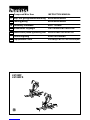
GB Compound Miter Saw INSTRUCTION MANUAL
S Kap- och geringskombinationssåg BRUKSANVISNING
N Lamellgjærsag BRUKSANVISNING
FIN Yhdistetty viistosaha KÄYTTÖOHJE
LV Kombinētais leņķzāģis LIETOŠANAS INSTRUKCIJA
LT
Kombinuotasis įžambiai pjaunantis pjūklas
NAUDOJIMO INSTRUKCIJA
EE Liit-eerungisaag KASUTUSJUHEND
RUS Торцовочная Пила
РУКОВОДСТВО ПО ЭКСПЛУАТАЦИИ
LS1040F
LS1040FS


5
ENGLISH (Original instructions)
Explanation of general view
1-1. Auxiliary plate
1-2. Hex bolt
1-3. Base
2-1. Auxiliary plate
2-2. Base
2-3. Hex bolt
2-4. Nut
3-1. Holder
4-1. Holder
4-2. Adjuster
4-3. Screw
5-1. Stopper pin
6-1. Bolt
7-1. Blade guard
8-1. Blade guard
9-1. Kerf board
9-2. Turn base
10-1. Socket wrench
10-2. Adjusting bolt
11-1. Top surface of turn base
11-2. Periphery of blade
11-3. Guide fence
12-1. Pointer
12-2. Lock lever
12-3. Grip
12-4. Miter scale
13-1. Lever
14-1. Lever
14-2. Bevel scale
14-3. Pointer
15-1. Lock-off button
15-2. Switch trigger
15-3. Lever
16-1. Lock-off button
16-2. Switch trigger
17-1. Light switch
18-1. Light
18-2. Light switch
19-1. Center cover
19-2. Socket wrench
19-3. Hex bolt
19-4. Blade guard
20-1. Socket wrench
20-2. Shaft lock
21-1. Spindle
21-2. Flange
21-3. Saw blade
21-4. Flange
21-5. Hex bolt
21-6. Ring
22-1. Blade case
22-2. Arrow
22-3. Saw blade
22-4. Arrow
23-1. Dust nozzle
23-2. Dust bag
23-3. Fastener
24-1. Support
24-2. Turn base
25-1. Sub-fence
26-1. Sub-fence
27-1. Vise rod
27-2. Screw
27-3. Vise knob
27-4. Vise arm
27-5. Guide fence
27-6. Holder assembly
27-7. Holder
28-1. Vise knob
28-2. Projection
28-3. Vise shaft
28-4. Base
29-1. Holder assembly
29-2. Holder
30-1. Holder assembly
30-2. Rod 12
33-1. Vise
33-2. Spacer block
33-3. Guide fence
33-4. Aluminum extrusion
33-5. Spacer block
34-1. Set plate
34-2. Holder
34-3. Screw
35-1. Stopper pin
37-1. Hex bolt
38-1. Triangular rule
38-2. Grip
38-3. Guide fence
39-1. Arm
39-2. Lever
39-3. 0 ゚ adjusting bolt
39-4. Hex nut
40-1. Triangular rule
40-2. Saw blade
40-3. Top surface of turn base
41-1. Arm
41-2. Bevel scale
41-3. Pointer
41-4. Turn base
42-1. Lever
42-2. Arm
42-3. Pointer
42-4. 45 ゚ bevel angle adjusting bolt
43-1. Pull out
43-2. Push
43-3. Lamp box
43-4. Screws
43-5. Fluorescent tube
44-1. Limit mark
45-1. Brush holder cap
45-2. Screwdriver
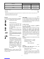
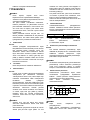
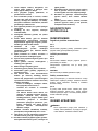
SPECIFICATIONS
Model LS1040F / LS1040FS
Blade diameter 255 mm - 260 mm
Blade body thickness 1.6 mm - 2.4 mm
Hole diameter
For all countries other than European countries 25.4 mm and 25 mm
For European countries 30 mm
Max. Miter angle Left 45° , Right 52°
Max. Bevel angle Left 45°
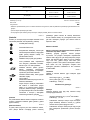
Max. Cutting capacities (H x W) with blade 260 mm in diameter

6
Miter angle
Bevel angle 0° 45° (left and right)
93 mm x 95 mm 93 mm x 67 mm
0° 69 mm x 135 mm 69 mm x 95 mm
53 mm x 95 mm 49 mm x 67 mm
45° (left) 35 mm x 135 mm 35 mm x 94 mm
No load speed (min-1) 4,600
Dimensions (L x W x H) 530 mm x 476 mm x 532 mm
Net weight 12.6 kg
Safety class /II
• Due to our continuing programme of research and development, the specifications herein are subject to change without notice.
• Specifications may differ from country to country.
• Weight according to EPTA-Procedure 01/2003
END217-3
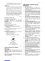
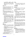
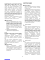
Symbols
The following show the symbols used for the equipment.
Be sure that you understand their meaning before use.
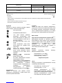
・ Read instruction manual.
・ DOUBLE INSULATION
・ To avoid injury from flying debris, keep
holding the saw head down, after
making cuts, until the blade has come
to a complete stop.
・ Do not place hand or fingers close to
the blade.
・ For your safety, remove the chips, small
pieces, etc. from the table top before
operation.
・ Always set SUB-FENCE to left position
when performing left bevel cuts. Failure
to do so may cause serious injury to
operator.
・ To loosen the bolt, turn it clockwise.
・ Only for EU countries
Do not dispose of electric equipment
together with household waste material!
In observance of European Directive
2002/96/EC on waste electric and
electronic equipment and its
implementation in accordance with
national law, electric equipment that
have reached the end of their life must
be collected separately and returned to
an environmentally compatible
recycling facility.
ENE004-1
Intended use
The tool is intended for accurate straight and miter
cutting in wood. With appropriate saw blades, aluminum
can also be sawed.
ENF002-2
Power supply
The tool should be connected only to a power supply of
the same voltage as indicated on the nameplate, and
can only be operated on single-phase AC supply. They
are double-insulated and can, therefore, also be used
from sockets without earth wire.
For Model LS1040F
ENF100-1
For public low-voltage distribution systems of
between 220 V and 250 V.
Switching operations of electric apparatus cause voltage
fluctuations. The operation of this device under
unfavorable mains conditions can have adverse effects
to the operation of other equipment. With a mains
impedance equal or less than 0.34 Ohms it can be
presumed that there will be no negative effects. The
mains socket used for this device must be protected with
a fuse or protective circuit breaker having slow tripping
characteristics.
ENG905-1
Noise
The typical A-weighted noise level determined according
to EN61029:
Sound pressure level (LpA) : 91 dB(A)
Sound power level (LWA) : 101 dB(A)
Uncertainty (K) : 3 dB(A)
Wear ear protection
ENG900-1
Vibration
The vibration total value (tri-axial vector sum)
determined according to EN61029:
Vibration emission (ah) : 2.5 m/s2 or less
Uncertainty (K) : 1.5 m/s2
ENG901-1
• The declared vibration emission value has been
measured in accordance with the standard test
method and may be used for comparing one tool
with another.

7
• The declared vibration emission value may also be
used in a preliminary assessment of exposure.
WARNING:
• The vibration emission during actual use of the
power tool can differ from the declared emission
value depending on the ways in which the tool is
used.
• Be sure to identify safety measures to protect the
operator that are based on an estimation of
exposure in the actual conditions of use (taking
account of all parts of the operating cycle such as
the times when the tool is switched off and when it
is running idle in addition to the trigger time).
ENH003-13
For European countries only
EC Declaration of Conformity
We Makita Corporation as the responsible
manufacturer declare that the following Makita
machine(s):
Designation of Machine:
Compound Miter Saw
Model No./ Type: LS1040F, LS1040FS
are of series production and
Conforms to the following European Directives:
2006/42/EC
And are manufactured in accordance with the following
standards or standardised documents:
EN61029
The technical documentation is kept by our authorised
representative in Europe who is:
Makita International Europe Ltd.
Michigan Drive, Tongwell,
Milton Keynes, Bucks MK15 8JD, England
30. 1. 2009
000230
Tomoyasu Kato
Director
Makita Corporation
3-11-8, Sumiyoshi-cho,
Anjo, Aichi, 446-8502, JAPAN
GEA010-1
General Power Tool Safety
Warnings
WARNING Read all safety warnings and all
instructions. Failure to follow the warnings and
instructions may result in electric shock, fire and/or
serious injury.
Save all warnings and instructions for
future reference.
ENB120-1
ADDITIONAL SAFETY RULES
FOR TOOL
1. Wear eye protection.
2. Keep hands out of path of saw blade. Avoid
contact with any coasting blade. It can still
cause severe injury.
3. Do not operate saw without guards in place.
Check blade guard for proper closing before
each use. Do not operate saw if blade guard
does not move freely and close instantly.
Never clamp or tie the blade guard into the
open position.
4. Do not perform any operation freehand. The
workpiece must be secured firmly against the turn
base and guide fence with the vise during all
operations. Never use your hand to secure the
workpiece.
5. Never reach around saw blade.
6.
Turn off tool and wait for saw blade to stop
before moving workpiece or changing settings.
7. Unplug tool before changing blade or
servicing.
8. Always secure all moving portions before
carrying the tool.
9. Stopper pin which locks the cutter head down
is for carrying and storage purposes only and
not for any cutting operations.
10.
Do not use the tool in the presence of
flammable liquids or gases.
The electrical
operation of the tool could create an explosion and
fire when exposed to flammable liquids or gases.
11. Check the blade carefully for cracks or
damage before operation.
Replace cracked or damaged blade
immediately.
12. Use only flanges specified for this tool.
13. Be careful not to damage the arbor, flanges
(especially the installing surface) or bolt.
Damage to these parts could result in blade
breakage.
14. Make sure that the turn base is properly
secured so it will not move during operation.
15.
For your safety, remove the chips, small pieces,
etc. from the table top before operation.
16. Avoid cutting nails. Inspect for and remove all
nails from the workpiece before operation.
17. Make sure the shaft lock is released before the
switch is turned on.
18. Be sure that the blade does not contact the
turn base in the lowest position.
19. Hold the handle firmly. Be aware that the saw
moves up or down slightly during start-up and
stopping.
20. Make sure the blade is not contacting the
workpiece before the switch is turned on.

8
21. Before using the tool on an actual workpiece,
let it run for a while. Watch for vibration or
wobbling that could indicate poor installation
or a poorly balanced blade.
22. Wait until the blade attains full speed before
cutting.
23. Stop operation immediately if you notice
anything abnormal.
24. Do not attempt to lock the trigger in the on
position.
25. Be alert at all times, especially during
repetitive, monotonous operations. Do not be
lulled into a false sense of security. Blades are
extremely unforgiving.
26. Always use accessories recommended in
this manual. Use of improper accessories
such as abrasive wheels may cause an injury.
27. Do not use the saw to cut other than wood,
aluminum or similar materials.
28. Connect miter saws to a dust collecting device
when sawing.
29. Select saw blades in relation to the material to
be cut.
30. Take care when slotting.
31. Replace the kerf board when worn.
32. Do not use saw blades manufactured from
high speed steel.
33. Some dust created from operation contains
chemicals known to cause cancer, birth
defects or other reproductive harm. Some
examples of these chemicals are:
• lead from lead-based-painted material and,
•
arsenic and chromium from
chemically-treated lumber.
Your risk from these exposures varies,
depending on how often you do this type of
work. To reduce your exposure to these
chemicals: work in a well ventilated area
and work with approved safety equipment,
such as those dust masks that are specially
designed to filter out microscopic particles.
34. To reduce the emitted noise, always be sure
that the blade is sharp and clean.
35. The operator is adequately trained in the use,
adjustment and operation of the machine.
36. Use correctly sharpened saw blades. Observe
the maximum speed marked on the saw blade.
37. Refrain from removing any cut-offs or other
parts of the workpiece from the cutting area
whilst the tool is running and the saw head is
not in the rest position.
38. Use only saw blades recommended by the
manufacturer which conform to EN847-1.
39. Wear gloves for handling saw blade (saw
blades shall be carried in a holder wherever
practicable) and rough material.
SAVE THESE INSTRUCTIONS.
INSTALLATION
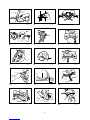
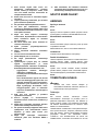
Installing auxiliary plate
Fig.1
Fig.2
Installing the auxiliary plate using the notch in the tool's
base and secure it by tightening the hex bolt.
Installing the holders
Fig.3
Fig.4
Install the holders on both sides of the base and secure
them with screws.
Adjust the adjusters so that they contact the floor surface.
NOTE:
In some countries, the holders may not have feet.
Bench mounting
When the tool is shipped, the handle is locked in the
lowered position by the stopper pin. Release the stopper
pin by lowering the handle slightly and pulling the
stopper pin.
Fig.5
This tool should be bolted with two bolts to a level and
stable surface using the bolt holes provided in the tool's
base. This will help prevent tipping and possible
personal injury.
Fig.6
FUNCTIONAL DESCRIPTION
CAUTION:
• Always be sure that the tool is switched off and
unplugged before adjusting or checking function on
the tool.
Blade guard
Fig.7
When lowering the handle, the blade guard rises
automatically. The guard is spring loaded so it returns to
its original position when the cut is completed and the
handle is raised. NEVER DEFEAT OR REMOVE THE
BLADE GUARD OR THE SPRING WHICH ATTACHES
TO THE GUARD.
In the interest of your personal safety, always maintain
the blade guard in good condition. Any irregular
operation of the blade guard should be corrected
immediately. Check to assure spring loaded return
action of guard. NEVER USE THE TOOL IF THE
BLADE GUARD OR SPRING ARE DAMAGED, FAULTY
OR REMOVED. DOING SO IS HIGHLY DANGEROUS
AND CAN CAUSE SERIOUS PERSONAL INJURY.
If the see-through blade guard becomes dirty, or
sawdust adheres to it in such a way that the blade is no
longer easily visible, unplug the saw and clean the guard

9
carefully with a damp cloth. Do not use solvents or any
petroleum-based cleaners on the plastic guard.
If the blade guard is especially dirty and vision through
the guard is impaired, use the supplied socket wrench to
loosen the hex bolt holding the center cover. Loosen the
hex bolt by turning it counterclockwise and raise the
blade guard and center cover. With the blade guard so
positioned, cleaning can be more completely and
efficiently accomplished. When cleaning is complete,
reverse procedure above and secure bolt. Do not
remove spring holding blade guard. If guard becomes
discolored through age or UV light exposure, contact a
Makita service center for a new guard. DO NOT
DEFEAT OR REMOVE GUARD.
Fig.8
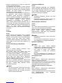
Kerf board
Fig.9
This tool is provided with the kerf board in the turn base
to minimize tearing on the exit side of a cut. If the kerf
groove has not yet been cut in the kerf board by the
factory, you should cut the groove before actually using
the tool to cut a workpiece. Switch on the tool and lower
the blade gently to cut a groove in the kerf board.
Maintaining maximum cutting capacity
Fig.10
Fig.11
This tool is factory adjusted to provide the maximum
cutting capacity for a 260 mm saw blade.
When installing a new blade, always check the lower limit
position of the blade and if necessary, adjust it as follows:
First, unplug the tool. Lower the handle completely. Use
the socket wrench to turn the adjusting bolt until the
periphery of the blade extends slightly below the top
surface of the turn base at the point where the front face of
the guide fence meets the top surface of the turn base.
With the tool unplugged, rotate the blade by hand while
holding the handle all the way down to be sure that the
blade does not contact any part of the lower base.
Re-adjust slightly, if necessary.
CAUTION:
• After installing a new blade, always be sure that
the blade does not contact any part of the lower
base when the handle is lowered completely.
Always do this with the tool unplugged.
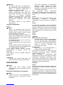
Adjusting the miter angle
Fig.12
Loosen the grip by turning counterclockwise. Turn the
turn base while pressing down the lock lever. When you
have moved the grip to the position where the pointer
points to the desired angle on the miter scale, securely
tighten the grip clockwise.
CAUTION:
• When turning the turn base, be sure to raise the
handle fully.
• After changing the miter angle, always secure the
turn base by tightening the grip firmly.
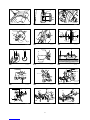
Adjusting the bevel angle
Fig.13
Fig.14
To adjust the bevel angle, loosen the lever at the rear of
the tool counterclockwise.
Push the handle to the left to tilt the saw blade until the
pointer points to the desired angle on the bevel scale.
Then tighten the lever clockwise firmly to secure the arm.
CAUTION:
• When tilting the saw blade, be sure to raise the
handle fully.
• After changing the bevel angle, always secure the
arm by tightening the lever clockwise.
Switch action
CAUTION:
• Before plugging in the tool, always check to see
that the switch trigger actuates properly and
returns to the "OFF" position when released.
• When not using the tool, remove the lock-off button
and store it in a secure place. This prevents
unauthorized operation.
• Do not pull the switch trigger hard without pressing
in the lock-off button. This can cause switch
breakage.
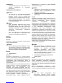
For European countries
Fig.15
To prevent the switch trigger from being accidentally
pulled, a lock-off button is provided.
To start the tool, raise the lever, depress the lock-off
button and pull the switch trigger. Release the switch
trigger to stop.
For all countries other than European countries
Fig.16
To prevent the switch trigger from being accidentally
pulled, a lock-off button is provided.
To start the tool, depress the lock-off button and pull the
switch trigger. Release the switch trigger to stop.
WARNING:
• NEVER use tool without a fully operative switch
trigger. Any tool with an inoperative switch is
HIGHLY DANGEROUS and must be repaired
before further usage.
• For your safety, this tool is equipped with a lock-off
button which prevents the tool from unintended
starting. NEVER use the tool if it runs when you
simply pull the switch trigger without pressing the
lock-off button. Return tool to a Makita service

10
center for proper repairs BEFORE further usage.
• NEVER tape down or defeat purpose and function
of lock-off button.
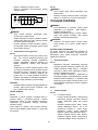
Lighting up the lamps
Fig.17
CAUTION:
• This is not a rainproof light. Do not wash the light in
water or use it in a rain or a wet area. Such a
conduct can cause an electric shock and fume.
• Do not touch the lens of the light, as it is very hot
while it is lighted or shortly after it is turned off. This
may cause a burn to a human body.
• Do not apply impact to the light, which may cause
damage or shorted service time to it.
• Do not keep casting the beam of the light to your
eyes. This can cause your eyes to be hurt.
• Do not cover the light with clothes, carton,
cardboard or similar objects while it is lighted,
which can cause a fire or an ignition.
Push the upper position of the switch for turning on the
light and the lower position for off.
Move the light to shift an area of lighting.
Fig.18
NOTE:
• Use a dry cloth to wipe the dirt off the lens of lamp.
Be careful not to scratch the lens of light, or it may
lower the illumination.
ASSEMBLY
CAUTION:
•
Always be sure that the tool is switched off and
unplugged before carrying out any work on the tool.
Installing or removing saw blade
CAUTION:
• Always be sure that the tool is switched off and
unplugged before installing or removing the blade.
• Use only the Makita socket wrench provided to
install or remove the blade. Failure to do so may
result in overtightening or insufficient tightening of
the hex bolt. This could cause a personal injury.
To remove the blade, use the socket wrench to loosen
the hex bolt holding the center cover by turning it
counterclockwise. Raise the blade guard and center
cover.
Fig.19
Press the shaft lock to lock the spindle and use the
socket wrench to loosen the hex bolt clockwise. Then
remove the hex bolt, outer flange and blade.
Fig.20
To install the blade, mount it carefully onto the spindle,
making sure that the direction of the arrow on the
surface of the blade matches the direction of the arrow
on the blade case. Install the outer flange and hex bolt,
and then use the socket wrench to tighten the hex bolt
(left-handed) securely counterclockwise while pressing
the shaft lock.
Fig.21
Fig.22
CAUTION:
For all countries other than European countries
• The silver ring 25.4 mm in outer diameter is
factory-installed onto the spindle. The black ring 25
mm in outer diameter is included as standard
equipment. Before mounting the blade onto the
spindle, always be sure that the correct ring for the
arbor hole of the blade you intend to use is
installed onto the spindle.
For European countries
• The ring 30 mm in outer diameter is
factory-installed onto the spindle.
Install the flange and hex bolt, and then use the socket
wrench to tighten the hex bolt securely counterclockwise
while pressing the shaft lock.
Return the blade guard and center cover to its original
position. Then tighten the hex bolt clockwise to secure
the center cover. Lower the handle to make sure that the
blade guard moves properly. Make sure shaft lock has
released spindle before making cut.
Dust bag
Fig.23
The use of the dust bag makes cutting operations clean
and dust collection easy. To attach the dust bag, fit it
onto the dust nozzle.
When the dust bag is about half full, remove the dust
bag from the tool and pull the fastener out. Empty the
dust bag of its contents, tapping it lightly so as to remove
particles adhering to the insides which might hamper
further collection.
NOTE:
• If you connect a Makita vacuum cleaner to this tool,
more efficient and cleaner operations can be
performed.
Securing workpiece
WARNING:
• It is extremely important to always secure the
workpiece properly and tightly with the vise. Failure
to do so can cause the tool to be damaged and/or
the workpiece to be destroyed. PERSONAL
INJURY MAY ALSO RESULT. Also, after a cutting
operation, DO NOT raise the blade until the blade
has come to a complete stop.
CAUTION:
• When cutting long workpieces, use supports that
are as high as the top surface level of the turn base.
Do not rely solely on the vertical vise and/or

11
horizontal vise to secure the workpiece.
Thin material tends to sag. Support workpiece over
its entire length to avoid blade pinch and possible
KICKBACK.
Fig.24
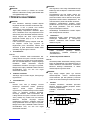
Sub-fence
Fig.25
This tool is equipped with the sub-fence. It should be
positioned as shown in the figure.
CAUTION:
•
When performing left bevel cuts, flip the fence over
to the left position as shown in the figure. Otherwise,
it will contact the blade or a part of the tool, causing
possible serious injury to the operator.
Fig.26
1. Vertical vise
Fig.27
The vertical vise can be installed in two positions on
either the left or right side of the guide fence or the
holder assembly (optional accessory). Insert the vise rod
into the hole in the guide fence or the holder assembly
and tighten the screw to secure the vise rod.
Position the vise arm according to the thickness and
shape of the workpiece and secure the vise arm by
tightening the screw. If the screw to secure the vise arm
contacts the guide fence, install the screw on the
opposite side of vise arm. Make sure that no part of the
tool contacts the vise when lowering the handle all the
way. If some part contacts the vise, re-position the vise.
Press the workpiece flat against the guide fence and the
turn base. Position the workpiece at the desired cutting
position and secure it firmly by tightening the vise knob.
CAUTION:
• The workpiece must be secured firmly against the
turn base and guide fence with the vise during all
operations.
2. Horizontal vise (optional accessory)
Fig.28
The horizontal vise can be installed on either the left or
right side of the base. When performing 15° or greater
miter cuts, install the horizontal vise on the side opposite
the direction in which the turn table is to be turned. By
turning the vise knob counterclockwise, the screw is
released and the vise shaft can be moved rapidly in and
out. By turning the vise knob clockwise, the screw
remains secured. To grip the workpiece, turn the vise
knob gently clockwise until the projection reaches its
topmost position, then fasten securely. If the vise knob is
forced in or pulled out while being turned clockwise, the
projection may stop at an angle. In this case, turn the
vise knob back counterclockwise until the screw is
released, before turning again gently clockwise.
The maximum width of the workpiece which can be
secured by the horizontal vise is 130 mm.
CAUTION:
• Grip the workpiece only when the projection is at
the topmost position. Failure to do so may result in
insufficient securing of the workpiece. This could
cause the workpiece to be thrown, cause damage
to the blade or cause the loss of control, which can
result in PERSONAL INJURY.
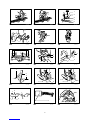
3. Holders and holder assembly (optional
accessories)
Fig.29
The holders and the holder assembly can be installed on
either side as a convenient means of supporting
workpieces horizontally. Install them as shown in the
figure. Then tighten the screws firmly to secure the
holders and the holder assembly.
When cutting long workpieces, use the holder-rod
assembly (optional accessory). It consists of two holder
assemblies and two rods 12.
Fig.30
CAUTION:
• Always support long workpieces level with the top
surface of the turn base for accurate cuts and to
prevent dangerous loss of control of the tool.
OPERATION
CAUTION:
• Before use, be sure to release the handle from the
lowered position by pulling the stopper pin.
• Make sure the blade is not contacting the
workpiece, etc. before the switch is turned on.
• Do not apply excessive pressure on the handle
when cutting. Too much force may result in
overload of the motor and/or decreased cutting
efficiency. Push down handle with only as much
force as is necessary for smooth cutting and
without significant decrease in blade speed.
• Gently press down the handle to perform the cut. If
the handle is pressed down with force or if lateral
force is applied, the blade will vibrate and leave a
mark (saw mark) in the workpiece and the
precision of the cut will be impaired.
1. Press cutting
Fig.31
Secure the workpiece with the vise. Switch on the
tool without the blade making any contact and wait
until the blade attains full speed before lowering.
Then gently lower the handle to the fully lowered
position to cut the workpiece. When the cut is
completed, switch off the tool and WAIT UNTIL THE
BLADE HAS COME TO A COMPLETE STOP before
returning the blade to its fully elevated position.

12
2. Miter cutting
Refer to the previously covered "Adjusting the
miter angle".
3. Bevel cut
Fig.32
Loosen the lever and tilt the saw blade to set the
bevel angle (Refer to the previously covered
"Adjusting the bevel angle"). Be sure to retighten the
lever firmly to secure the selected bevel angle safely.
Secure the workpiece with a vise. Switch on the tool
without the blade making any contact and wait until
the blade attains full speed. Then gently lower the
handle to the fully lowered position while applying
pressure in parallel with the blade. When the cut is
completed, switch off the tool and WAIT UNTIL THE
BLADE HAS COME TO A COMPLETE STOP before
returning the blade to its fully elevated position.
CAUTION:
• Always be sure that the blade will move down to
bevel direction during a bevel cut. Keep hands out
of path of saw blade.
• During a bevel cut, it may create a condition
whereby the piece cut off will come to rest against
the side of the blade. If the blade is raised while the
blade is still rotating, this piece may be caught by
the blade, causing fragments to be scattered which
is dangerous. The blade should be raised ONLY
after the blade has come to a complete stop.
• When pressing the handle down, apply pressure
parallel to the blade. If the pressure is not parallel
to the blade during a cut, the angle of the blade
might be shifted and the precision of the cut will be
impaired.
• Always set the sub-fence to the left position when
performing left bevel cuts.
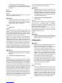
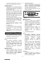
4. Compound cutting
Compound cutting is the process in which a bevel
angle is made at the same time in which a miter
angle is being cut on a workpiece. Compound
cutting can be performed at angle shown in the
table.
Miter angle
Bevel angle
Left and Right 0 - 45
45
006389
When performing compound cutting, refer to "Press
cutting", "Miter cutting" and "Bevel cut" explanations.
5. Cutting aluminum extrusion
Fig.33
When securing aluminum extrusions, use spacer
blocks or pieces of scrap as shown in the figure to
prevent deformation of the aluminum. Use a
cutting lubricant when cutting the aluminum
extrusion to prevent build-up of the aluminum
material on the blade.
CAUTION:
• Never attempt to cut thick or round aluminum
extrusions. Thick aluminum extrusions may come
loose during operation and round aluminum
extrusions cannot be secured firmly with this tool.
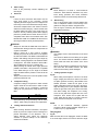
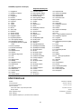
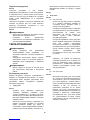
6. Wood facing
Use of wood facing helps to assure splinter-free
cuts in workpieces. Attach a wood facing to the
guide fence using the holes in the guide fence.
See the figure concerning the dimensions for a
suggested wood facing.
Over 10mm (3/8") Over 460mm (18-1/8")
11
90mm
(3-9/16")
25mm
(1")
90mm
(3-9/16")
107mm
(4-7/32")
90mm
(3-9/16")
107mm
(4-7/32")
001790
CAUTION:
• Use straight wood of even thickness as the wood
facing.
• Use screws to attach the wood facing to the guide
fence. The screws should be installed so that the
screw heads are below the surface of the wood
facing.
• When the wood facing is attached, do not turn the
turn base with the handle lowered. The blade
and/or the wood facing will be damaged.
7. Cutting repetitive lengths
Fig.34
When cutting several pieces of stock to the same
length, ranging from 240 mm to 400 mm, use of the
set plate (optional accessory) will facilitate more
efficient operation. Install the set plate on the
holder (optional accessory) as shown in the figure.
Align the cutting line on your workpiece with either
the left or right side of the groove in the kerf board,
and while holding the workpiece from moving,
move the set plate flush against the end of the
workpiece. Then secure the set plate with the
screw. When the set plate is not used, loosen the
screw and turn the set plate out of the way.
NOTE:
• Use of the holder-rod assembly (optional
accessory) allows cutting repetitive lengths up to
2,200 mm (7.2 ft.) approximately.
Carrying tool
Fig.35
Make sure that the tool is unplugged. Secure the blade
at 0° bevel angle and the turn base at left miter angle
1. Hole

13
fully. Lower the handle fully and lock it in the lowered
position by pushing in the stopper pin.
Carry the tool by carrying grip as shown in the figure. If
you remove the holders, dust bag, etc., you can carry
the tool more easily.
Fig.36
CAUTION:
• Always secure all moving portions before carrying
the tool.
• Stopper pin is for carrying and storage purposes
only and not for any cutting operations.
MAINTENANCE
CAUTION:
• Always be sure that the tool is switched off and
unplugged before attempting to perform inspection
or maintenance.
• Never use gasoline, benzine, thinner, alcohol or
the like. Discoloration, deformation or cracks may
result.
WARNING:
• Always be sure that the blade is sharp and clean
for the best and safest performance.
Adjusting the cutting angle
This tool is carefully adjusted and aligned at the factory,
but rough handling may have affected the alignment. If
your tool is not aligned properly, perform the following:
1. Miter angle
Fig.37
Loosen the grip which secures the turn base. Turn
the turn base so that the pointer points to 0° on the
miter scale. Tighten the grip and loosen the hex
bolts securing the guide fence using the socket
wrench.
Lower the handle fully and lock it in the lowered
position by pushing in the stopper pin. Square the
side of the blade with the face of the guide fence
using a triangular rule, try-square, etc. Then
securely tighten the hex bolts on the guide fence in
the order from the right side.
Fig.38
2. Bevel angle
Fig.39
(1) 0° bevel angle
Lower the handle fully and lock it in the
lowered position by pushing in the stopper
pin. Loosen the lever at the rear of the tool.
Loosen the hex nut and turn the 0° bevel
angle adjusting bolt on the right side of the
arm two or three revolutions clockwise to tilt
the blade to the right.
Carefully square the side of the blade with
the top surface of the turn base using the
triangular rule, try-square, etc. by turning the
0° bevel angle adjusting bolt
counterclockwise. Then tighten the hex nut to
secure the 0° bevel angle adjusting bolt and
tighten the lever securely.
Fig.40
Make sure that the pointer on the turn base
point to 0° on the bevel scale on the arm. If it
does not point to 0°, loosen the screw which
secures the pointer and adjust the pointer so
that it will point to 0°.
Fig.41
(2) 45° bevel angle
Fig.42
Adjust the 45° bevel angle only after
performing 0° bevel angle adjustment. To
adjust left 45° bevel angle, loosen the lever
and tilt the blade to the left fully. Make sure
that the pointer on the arm points to 45° on
the bevel scale on the arm holder. If the
pointer does not point to 45°, turn the 45°
bevel angle adjusting bolt on the left side of
the arm until the pointer points to 45°.
Replacing fluorescent tube
Fig.43
CAUTION:
• Always be sure that the tool is switched off and
unplugged before replacing the fluorescent tube.
• Do not apply force, impact or scratch to a
fluorescent tube, which can cause a glass of the
fluorescent tube to be broken resulting in a injury to
you or your bystanders.
• Leave the florescent tube for a while immediately
after a use of it and then replace it. If not. You may
burn yourself.
Remove screws, which secure Lamp Box for the light.
Pull out the Lamp Box keeping pushing lightly the upper
position of it as illustrated on the left.
Pull out the fluorescent tube and then replace it with
Makita original new one.
Replacing carbon brushes
Fig.44
Remove and check the carbon brushes regularly.
Replace when they wear down to the limit mark. Keep
the carbon brushes clean and free to slip in the holders.
Both carbon brushes should be replaced at the same
time. Use only identical carbon brushes.
Use a screwdriver to remove the brush holder caps.
Take out the worn carbon brushes, insert the new ones
and secure the brush holder caps.
Fig.45

14
After use
• After use, wipe off chips and dust adhering to the
tool with a cloth or the like. Keep the blade guard
clean according to the directions in the previously
covered section titled "Blade guard". Lubricate the
sliding portions with machine oil to prevent rust.
To maintain product SAFETY and RELIABILITY, repairs,
any other maintenance or adjustment should be
performed by Makita Authorized Service Centers,
always using Makita replacement parts.
OPTIONAL ACCESSORIES
CAUTION:
• These accessories or attachments are
recommended for use with your Makita tool
specified in this manual. The use of any other
accessories or attachments might present a risk of
injury to persons. Only use accessory or
attachment for its stated purpose.
If you need any assistance for more details regarding
these accessories, ask your local Makita Service Center.
• Steel & Carbide-tipped saw blade
• Auxiliary plate
• Vise assembly (Horizontal vise)
• Vertical vise
• Socket wrench 13
• Holder set
• Holder assembly
• Holder rod assembly
• Set plate
• Dust bag
• Triangular rule
• Lock-off button (2 pcs.)
• Fluorescent tube
NOTE:
• Some items in the list may be included in the tool
package as standard accessories. They may differ
from country to country.

15
SVENSKA (Originalbruksanvisning)
Förklaring till översiktsbilderna
1-1. Extraskiva
1-2. Sexkantskruv
1-3. Bottenplatta
2-1. Extraskiva
2-2. Bottenplatta
2-3. Sexkantskruv
2-4. Mutter
3-1. Hållare
4-1. Hållare
4-2. Inställningsring
4-3. Skruv
5-1. Låstapp
6-1. Bult
7-1. Klingskydd
8-1. Klingskydd
9-1. Spårbädd
9-2. Geringsskiva
10-1. Hylsnyckel
10-2. Inställningsbult
11-1. Geringsskivans ovansida
11-2. Klingans ytterkant
11-3. Anslag
12-1. Pil
12-2. Låsknapp
12-3. Handtag
12-4. Geringsskala
13-1. Spak
14-1. Spak
14-2. Vinkelskala
14-3. Pil
15-1. Säkerhetsknapp
15-2. Avtryckare
15-3. Spak
16-1. Säkerhetsknapp
16-2. Avtryckare
17-1. Lampströmbrytare
18-1. Lampa
18-2. Lampströmbrytare
19-1. Mitthölje
19-2. Hylsnyckel
19-3. Sexkantskruv
19-4. Klingskydd
20-1. Hylsnyckel
20-2. Spindellås
21-1. Spindel
21-2. Fläns
21-3. Sågblad
21-4. Fläns
21-5. Sexkantskruv
21-6. Ring
22-1. Klingkåpa
22-2. Pil
22-3. Sågblad
22-4. Pil
23-1. Dammunstycke
23-2. Dammpåse
23-3. Fästanordning
24-1. Stöd
24-2. Geringsskiva
25-1. Stödanhåll
26-1. Stödanhåll
27-1. Stång till tving
27-2. Skruv
27-3. Tvingens ratt
27-4. Tvingarm
27-5. Anslag
27-6. Hållaruppsättning
27-7. Hållare
28-1. Tvingens ratt
28-2. Utskjutande del
28-3. Axel till tving
28-4. Bottenplatta
29-1. Hållaruppsättning
29-2. Hållare
30-1. Hållaruppsättning
30-2. Stång 12
33-1. Tving
33-2. Distanskloss
33-3. Anslag
33-4. Aluminiumstycke
33-5. Distanskloss
34-1. Batterilock
34-2. Hållare
34-3. Skruv
35-1. Låstapp
37-1. Sexkantskruv
38-1. Vinkelhake
38-2. Handtag
38-3. Anslag
39-1. Arm
39-2. Spak
39-3. Justeringsskruv 0 ゚
39-4. Sexkantmutter
40-1. Vinkelhake
40-2. Sågblad
40-3. Geringsskivans ovansida
41-1. Arm
41-2. Vinkelskala
41-3. Pil
41-4. Geringsskiva
42-1. Spak
42-2. Arm
42-3. Pil
42-4. Justeringsskruv 45 ゚ vinkel
43-1. Dra ut
43-2. Tryck
43-3. Lamphus
43-4. Skruvar
43-5. Lysrör
44-1. Slitmarkering
45-1. Kolhållarlock
45-2. Skruvmejsel
SPECIFIKATIONER
Modell LS1040F / LS1040FS
Bladdiameter 255 mm - 260 mm
Klingtjocklek 1,6 mm - 2,4 mm
Håldiameter
För alla länder utanför Europa 25,4 mm och 25 mm
För länder i Europa 30 mm
Max. geringsvinkel Vänster 45° , höger 52°
Max. sågvinkel Vänster 45°
Max. sågkapacitet (H x B) med 260 mm bladdiameter.

16
Geringsvinkel
Vinkel för vinkelsågning 0° 45° (vänster och höger)
93 mm x 95 mm 93 mm x 67 mm
0° 69 mm x 135 mm 69 mm x 95 mm
53 mm x 95 mm 49 mm x 67 mm
45° (vänster) 35 mm x 135 mm 35 mm x 94 mm
Obelastat varvtal (min-1) 4 600
Mått (L x B x H) 530 mm x 476 mm x 532 mm
Vikt 12,6 kg
Säkerhetsklass /II
• På grund av vårt pågående program för forskning och utveckling kan dessa specifikationer ändras utan föregående meddelande.
• Specifikationerna kan variera mellan olika länder.
• Vikt i enlighet med EPTA-procedur 01/2003
END217-3
Symboler
Följande visar symbolerna som används för
utrustningen. Se till att du förstår innebörden innan du
använder borrmaskinen.
・ Läs bruksanvisningen.
・ DUBBEL ISOLERING
・ Undvik skador från flygande
materialrester, fortsätt efter sågning att
hålla ned såghuvudet tills bladet har
stannat helt.
・ Håll inte handen eller fingrarna i
närheten av sågbladet.
・ Avlägsna av säkerhetsskäl spån,
småbitar etc. från bordets översida
innan arbetet påbörjas.
・ Ställ alltid STÖDANHÅLLET i
vänsterläget vid vinkelsågning åt
vänster. I annat fall kan användaren
skadas allvarligt.
・ Lossa bulten genom att skruva den
medurs.
・ Gäller endast inom EU
Elektrisk utrustning får inte kastas i
hushållsavfallet!
Enligt direktivet 2002/96/EC som avser
deponering av elektrisk och elektronisk
utrustning samt tillhörande föreskrifter i
det aktuella landets lagstiftning ska
uttjänt elektrisk utrustning sopsorteras
och lämnas till miljöstation för
återvinning.
ENE004-1
Användningsområde
Verktyget är avsett för exakt rät- och geringssågning i trä.
Med lämpliga sågblad kan man även såga i aluminium.
ENF002-2
Strömförsörjning
Maskinen får endast anslutas till elnät med samma
spänning som anges på typplåten och med enfasig
växelström. De är dubbelisolerade och får därför också
anslutas i ojordade vägguttag.
För modell LS1040F
ENF100-1
Avsedd för elnät med 220 - 250 V.
Att starta och stänga av elektriska apparater medför
spänningsfluktuationer. Om denna maskin används
under ogynnsamma förhållanden kan funktioner hos
annan utrustning påverkas negativt. I elnät med ett
motstånd på högst 0,34 Ohm är det rimligt att anta att
negativa effekter inte förekommer. Nätuttaget för den här
enheten måste vara försett med trög säkring eller
skyddsbrytare.
ENG905-1
Buller
Typiska A-vägda bullernivån är mätt enligt EN61029:
Ljudtrycksnivå (LpA): 91 dB(A)
Ljudtrycksnivå (LWA): 101 dB(A)
Mättolerans (K) : 3 dB(A)
Använd hörselskydd
ENG900-1
Vibration
Vibrationens totalvärde (tre-axlars vektorsumma) mätt
enligtEN61029:
Vibrationsemission (ah): 2,5 m/s2 eller mindre
Mättolerans (K): 1,5 m/s2
ENG901-1
• Det deklarerade vibrationsemissionsvärdet har
uppmätts i enlighet med standardtestmetoden och
kan användas för jämförandet av en maskin med
en annan.
• Det deklarerade vibrationsemissionsvärdet kan
också användas i preliminär bedömning av
exponering för vibration.

17
VARNING!
• Viberationsemissionen under faktisk användning
av maskinen kan skilja sig från det deklarerade
emissionsvärdet, beroende på hur maskinen
används.
• Se till att hitta säkerhetsåtgärder som kan skydda
användaren och som grundar sig på en
uppskattning av exponering i verkligheten (ta med i
beräkningen alla delar av användandet såsom
antal gånger maskinen är avstängd och när den
körs på tomgång samt då startomkopplaren
används).
ENH003-13
Gäller endast Europa
EU-konformitetsdeklaration
Vi Makita Corporation som ansvariga tillverkare
deklarerar att följande Makita-maskin(er):
Maskinbeteckning:
Kap- och geringskombinationssåg
Modellnr./-typ: LS1040F, LS1040FS
är serieproduktionstillverkad och
Följer följande EU-direktiv:
2006/42/EC
Och är tillverkade enligt följande standarder eller
standardiseringsdokument:
EN61029
Den tekniska dokumentationen förs av vår auktoriserade
representant i Europa som är:
Makita International Europe Ltd.
Michigan Drive, Tongwell,
Milton Keynes, Bucks MK15 8JD, England
30. 1. 2009
000230
Tomoyasu Kato
Direktör
Makita Corporation
3-11-8, Sumiyoshi-cho,
Anjo, Aichi, 446-8502, JAPAN
GEA010-1
Allmänna säkerhetsvarningar för
maskin
VARNING Läs igenom alla säkerhetsvarningar
och instruktioner. Underlåtenhet att följa varningar och
instruktioner kan leda till elektrisk stöt, brand och/eller
allvarliga personskador.
Spara alla varningar och instruktioner
för framtida referens.
ENB120-1
YTTERLIGARE
SÄKERHETSANVISNINGAR FÖR
MASKINEN
1. Använd ögonskydd
2. Håll händerna borta från bladets såglinje.
Undvik kontakt med sågklingan. Den kan
fortfarande orsaka allvarliga skador.
3. Använd inte sågen om inte skydden är på
plats. Kontrollera att det nedre skyddet är
stängt före varje sågning. Använd inte sågen
om det nedre skyddet kärvar och inte stängs
omedelbart. Kila aldrig fast klingskyddet i
öppet läge.
4. Utför aldrig sågning på frihand. Arbetsstycket
måste sitta fast ordentligt mot bordet och
anslaget med skruvstycket under alla
arbetsmoment. Håll aldrig arbetsstycket med
handen.
5. Sträck dig aldrig runt sågbladet.
6. Stäng av verktyget och vänta tills sågbladet
stannat innan du flyttar arbetsstycket eller
ändrar inställningar.
7. Ta ut nätsladden före byte av sågblad eller
service.
8. Fäst alltid alla rörliga delar innan du bär
verktyget.
9. Låspinnen som låser såghuvudet på plats är
endast avsedd att användas vid förvaring eller
transport och inte för sågning.
10. Använd inte maskiner i närheten av
lättantändliga vätskor eller gaser. När
maskinen är igång kan den skapa en explosion
och brand när den utsätts för lättantändliga
vätskor eller gaser.
11. Kontrollera att bladet inte är skadat eller
sprucket före användning.
Byt omedelbart ut ett skadat eller sprucket
sågblad.
12. Använd endast flänsar avsedda för den här
maskinen.
13. Var försiktig så att inte axeln, flänsarna
(särskilt monteringsytan) eller bulten inte
skadas. Skador på någon av dessa delar kan
medföra att bladet förstörs.
14. Se till att bordet är ordentligt fast, så att det
inte rör sig under arbetet.
15. Avlägsna av säkerhetsskäl spån, småbitar etc.
från bordets översida innan arbetet påbörjas.
16. Undvik att såga i spik. Kontrollera
arbetsstycket och ta bort alla spikar före
arbetet.
17. Se till att spindellåset är öppet innan
strömbrytaren slås på.
18. Kontrollera att bladet i sin lägsta position inte
vidrör bordet.

18
19. Håll handtaget stadigt. Var uppmärksam på att
sågen rör sig något upp och ned under start
och stopp.
20. Se till att sågbladet inte är i kontakt med
arbetsstycket innan du trycker på avtryckaren.
21. Låt verktyget vara igång en stund innan det
används på arbetsstycket. Kontrollera att
sågbladet inte vibrerar eller skakar vilket kan
innebära att den är felaktigt monterad eller
dåligt balanserad.
22. Vänta tills bladet når full hastighet innan du
skär.
23. Stanna maskinen omedelbart om du lägger
märke till något onormalt.
24. Försök inte att låsa avtryckaren i påslaget
läge.
25. Var alltid uppmärksam, särskilt under
upprepade och monotona arbeten. Låt dig inte
vaggas in i falsk säkerhet. Sågblad är mycket
farliga.
26. Använd alltid de tillbehör som
rekommenderas i denna bruksanvisning.
Opassande tillbehör som till exempel
sliprondeller kan orsaka skada om de
används.
27. Använd inte sågen till annat än för sågning av
trä, aluminium eller liknande material.
28. Anslut geringssågar till en anordning för
dammuppsamling innan sågning.
29. Välj sågblad som passar det material som
skall sågas.
30. Var försiktig vid spårsågning.
31. Byt ut sågskäret när det är slitet.
32. Använd inte sågblad som tillverkats av
snabbstål.
33. Visst damm som skapas vid användning
innehåller kemikalier som kan orsaka cancer,
födelsedefekter eller annan skada vid
fortplantning. Några exempel på dessa
kemikalier är:
• bly från material målat med blybaserad
färg och
• arsenik och krom från kemiskt behandlat
virke.
Riskerna vid exponering varierar beroende
på hur ofta du utför denna typ av arbete.
För att minska risken för exponering av
dessa kemikalier: arbeta i ett välventilerat
område och arbeta med godkänd
säkerhetsutrustning som till exempel
dammask vilken skapats speciellt för
filtrering av mikroskopiska partiklar.
34. För att minska bullret, se alltid till att
sågbladet är vasst och rengjort.
35. Att operatören är tillräckligt utbildad i
användning, justering och drift av maskinen.
36. Använd korrekt slipade sågblad. Observera
maximal hastighet som markerats på
sågbladet.
37. Ta inte bort avsågade bitar eller andra delar av
arbetsstycket från sågningsområdet när
maskinen körs och såghuvudet inte är i sitt
viloläge.
38. Använd endast de sågblad som
rekommenderas av tillverkaren vilka
överensstämmer med EN847-1.
39. Bär alltid handskar när du hanterar sågblad
(sågblad ska alltid bäras i en hållare om det är
möjligt) och grova material.
SPARA DESSA ANVISNINGAR.
INSTALLATION
Montering av stödplatta
Fig.1
Fig.2
Montera stödplattan med hjälp av fästet i sågbordet och
lås fast den genom att skruva åt insexbulten.
Montering av hållarna
Fig.3
Fig.4
Montera hållarna på båda sidor om sågbordet och fäst
dem med skruvar.
Justera fötterna så att de kommer i kontakt med golvet.
OBS!
I vissa länder kan det hända att hållarna inte har fötter.
Bänkmontering
När maskinen levereras från fabriken är handtaget låst i
nedsänkt läge av låstappen. Ta bort låstappen genom att
sänka handtaget en aning och sedan dra ut låstappen.
Fig.5
Maskinen skall fästas på en plan och stabil yta med två
bultar, i de bulthål som finns i maskinens bottenplatta.
Detta förhindrar att maskinen välter och orsakar
personskada.
Fig.6
FUNKTIONSBESKRIVNING
FÖRSIKTIGT!
• Se alltid till att maskinen är avstängd och
nätsladden urdragen innan du justerar eller
funktionskontrollerar maskinen.
Klingskydd
Fig.7
När du sänker handtaget lyfts klingskyddet automatiskt.
Klingskyddet är försett med en fjäder så att det går
tillbaka till ursprungsläget när sågningen är avslutad och

19
handtaget höjs. BLOCKERA ALDRIG ELLER
AVLÄGSNA ALDRIG KLINGSKYDDET ELLER
FJÄDERN SOM FÄSTER KLINGSKYDDET.
För din personliga säkerhet bör klingskyddet alltid hållas
i gott skick. Om klingskyddet inte fungerar som det ska
måste detta åtgärdas direkt. Kontrollera även att fjädern
gör att klingskyddet går tillbaka. ANVÄND ALDRIG
MASKINEN OM KLINGSKYDDET ELLER FJÄDERN
ÄR SKADADE, INTE FUNGERAR KORREKT ELLER
ÄR BORTTAGNA. SÅDAN ANVÄNDNING ÄR MYCKET
FARLIG OCH KAN ORSAKA ALLVARLIGA
PERSONSKADOR.
Om det genomskinliga klingskyddet blir smutsigt eller
om sågspån fastnar på det så att inte klingan syns bra,
måste maskinen kopplas ur och skyddet rengöras noga
med en fuktig trasa. Använd inte lösningsmedel eller
petroleumbaserade rengöringsmedel då det skadar
plasten i skyddet.
Om klingskyddet är mycket smutsigt så att du ej kan se
genom det lossar du insexbulten som fäster mitthöljet,
med hylsnyckeln. Lossa därefter insexbulten moturs och
lyft klingskyddet och mitthöljet. Med klingskyddet i detta
läge är en mer noggrann och effektiv rengöring möjlig.
När rengöringen är klar gör du bara på motsatt sätt och
drar åt bulten. Ta inte bort det fjäderupphängda
klingskyddet. Om klingskyddet blir missfärgat med tiden
eller p.g.a. UV-ljus, kontaktar du ett av Makitas
servicecenter för att få ett nytt klingskydd.
KLINGSKYDDET FÅR ALDRIG BLOCKERAS ELLER
TAS BORT.
Fig.8
Spårbädd
Fig.9
Denna maskin är utrustad med spårbädden infälld i
geringsskivan, för att göra slitaget vid utgången av
sågningen så minimal som möjligt. Om spårbädden inte
har sågats i geringsskivan av fabriken, skall du först
såga spåret innan du börjar använder maskinen för att
såga ett arbetsstycke. Sätt på maskinen och sänk ner
klingan försiktigt för att såga ett spår i spårbädden.
Upprätthållande av maximal sågkapacitet
Fig.10
Fig.11
Denna maskin är fabriksinställd för att ge en maximal
sågkapacitet med en 260 mm sågklinga.
När en ny klinga monteras måste klingans lägsta
position alltid kontrolleras och om det är nödvändigt,
justera den enligt följande:
Koppla först bort maskinen från elnätet. Sänk handtaget
så långt det går. Vrid inställningsbulten med hylsnyckeln
tills klingans ytterkant sticker ut en aning under
geringsskivan, vid den punkt där anhållets framsida
kommer i kontakt med geringsskivans ovansida.
Kontrollera att maskinens nätsladd är utdragen och
snurra på klingan för hand, medan handtaget hålls ner
fullständigt, och kontrollera att klingan inte kommer i
kontakt med någon del av undre basplattan. Finjustera
inställningen vid behov.
FÖRSIKTIGT!
• Efter monteringen av en ny klinga måste du alltid
kontrollera att klingan inte går emot någon del av
den undre basplattan när handtaget sänks helt.
Utför denna kontroll endast när maskinen är
urkopplad.
Justering av geringsvinkeln
Fig.12
Lossa handtaget genom att vrida det moturs. Vrid
geringsskivan medan låsspaken hålls nedtryckt. Dra åt
handtaget ordentligt genom att vrida det medurs, när
handtaget flyttats till det läge där pekaren indikerar
önskad vinkel på geringsskalan.
FÖRSIKTIGT!
• Lyft handtaget maximalt när geringsskivan vrids.
• Fäst alltid geringsskivan genom att dra åt
handtaget ordentligt efter ändringen av
geringsvinkeln.
Justering av vinkeln vid vinkelsågning
Fig.13
Fig.14
För att ändra vinkeln för vinkelsågning, lossar du spaken
på maskinens baksida genom att dra den moturs.
Tryck handtaget till vänster för att luta sågklingan tills
pekaren indikerar önskad vinkel på vinkelskalan. Dra
sedan åt spaken ordentligt medurs för att fästa armen.
FÖRSIKTIGT!
• Lyft handtaget maximalt när sågklingan lutas.
• Fäst alltid armen genom att dra åt spaken medurs
efter ändringen av vinkeln för vinkelsågning.
Avtryckarens funktion
FÖRSIKTIGT!
• Innan du ansluter maskinen till elnätet ska du
kontrollera att avtryckaren fungerar och återgår till
läget "OFF" när du släpper den.
• När maskinen inte används skall
säkerhetsknappen tas bort och förvaras på ett
säkert ställe. På så vis kan ingen obehörig
använda sågen.
• Tryck inte in avtryckaren utan att ha tryckt in
säkerhetsspärren, annars kan avtryckaren gå
sönder.
För länder i Europa
Fig.15
Säkerhetsknappens funktion är att förhindra att
avtryckaren oavsiktligt trycks in.
För att starta maskinen lyfter du upp spaken, trycker in
säkerhetsknappen och sedan avtryckaren. Släpp

20
avtryckaren för att stoppa maskinen.
För alla länder utanför Europa
Fig.16
Säkerhetsknappens funktion är att förhindra att
avtryckaren oavsiktligt trycks in.
För att starta maskinen trycker du först in
säkerhetsknappen och sedan trycker du in avtryckaren.
Släpp avtryckaren för att stoppa maskinen.
VARNING!
• Använd ALDRIG maskinen om inte avtryckaren
fungerar riktigt. Att använda maskinen när inte
avtryckaren fungerar är MYCKET FARLIGT.
Reparera den före fortsatt användning.
• Denna maskin är utrustat med en säkerhetsknapp
som förhindrar oavsiktlig start för din säkerhet.
Använd ALDRIG maskinen om den startar när du
trycker in avtryckaren utan att ha tryckt in
säkerhetsknappen. Returnera maskinen till ett
MAKITA servicecenter för reparation INNAN du
fortsätter att använda den.
• Du får ALDRIG tejpa fast säkerhetsknappen i
intryckt läge, eller på annat sätt förhindra dess
funktion.
Tända lamporna
Fig.17
FÖRSIKTIGT!
• Lampan är inte vattentät. Den får inte tvättas i
vatten, eller användas i regn eller på våta platser.
Det kan leda till elektriska stötar och rökutveckling.
• Vidrör inte lampans lins eftersom den är mycket
varm så länge lampan lyser och en stund efter det
att den har släckts. Detta kan orsaka brännskador.
• Utsätt inte lampan för slag eftersom det kan orsaka
skador på lampan eller förkorta dess livslängd.
• Lys inte mot ögonen. Det kan orsaka synskador.
• Täck inte för lampan med tyg, tjocka papper,
kartong eller liknande material så länge den lyser.
Det kan leda till antändning och eldsvåda.
Tryck på strömbrytarens övre del för att tända lampan,
och den undre delen för att släcka den.
Du kan ändra lampans inriktning så att den lyser på ett
annat område.
Fig.18
OBS!
• Använd en torr tygduk för att torka bort smuts från
lampans lins. Var försiktig så att inte lampans lins
repas, eftersom ljuset då kan bli svagare.
MONTERING
FÖRSIKTIGT!
• Se alltid till att maskinen är avstängd och
nätsladden urdragen innan maskinen repareras.
Montering eller borttagning av sågblad
FÖRSIKTIGT!
• Kontrollera alltid att maskinen är avstängd och att
nätkabeln är utdragen innan sågbladet monteras
eller tas bort.
• Använd endast medföljande hylsnyckel från Makita
för att montera eller demontera klingan. Om inte
detta görs kan det leda till att insexbulten dras åt
för hårt eller för löst, vilket kan orsaka
personskada.
När du ska ta ur klingan använder du hylsnyckeln för att
lossa på insexbulten som håller fast mitthöljet, genom att
vrida den moturs. Lyft på klingskyddet och mitthöljet.
Fig.19
Tryck på spindellåset för att låsa spindeln och använd
hylsnyckeln för att lossa på insexbulten genom att vrida
den medurs. Ta sedan bort insexbulten, den yttre
flänsen och klingan.
Fig.20
För att montera klingan sätter du den försiktigt på
spindeln och ser till att riktningen på den pil som finns på
klingans sida stämmer överens med pilens riktning på
klinghöljet. Montera den yttre flänsen och insexbulten,
och använd sedan hylsnyckeln för att dra åt insexbulten
(vänstergängad, dra åt moturs) ordentligt medan du
håller in spindellåset.
Fig.21
Fig.22
FÖRSIKTIGT!
För alla länder utanför Europa
• Silverringen med en yttre diameter på 25,4 mm är
fabriksmonterad på spindeln. Den svarta ringen
med en yttre diameter på 25 mm medföljer som
standardutrustning. Innan bladet monteras på
spindeln, skall du alltid se till att korrekt insatsring
för axelhålet på det blad du skall använda
monteras på spindeln.
För länder i Europa
• Ringen med en ytterdiameter på 30 mm är
fabriksmonterad på spindeln.
Montera den yttre flänsen och insexbulten, och använd
sedan hylsnyckeln för att dra åt insexbulten (moturs)
ordentligt medan du håller in spindellåset.
Sätt tillbaka klingskyddet och mitthöljet i dess
ursprungliga läge. Dra sedan åt insexbulten medurs för
att fästa mitthöljet. Sänk ner handtaget för att försäkra
dig om att klingskyddet fungerar som det ska.
Kontrollera att spindellåset inte längre låser fast spindeln
innan du försöker såga.
Sidan laddas...
Sidan laddas...
Sidan laddas...
Sidan laddas...
Sidan laddas...
Sidan laddas...
Sidan laddas...
Sidan laddas...
Sidan laddas...
Sidan laddas...
Sidan laddas...
Sidan laddas...
Sidan laddas...
Sidan laddas...
Sidan laddas...
Sidan laddas...
Sidan laddas...
Sidan laddas...
Sidan laddas...
Sidan laddas...
Sidan laddas...
Sidan laddas...
Sidan laddas...
Sidan laddas...
Sidan laddas...
Sidan laddas...
Sidan laddas...
Sidan laddas...
Sidan laddas...
Sidan laddas...
Sidan laddas...
Sidan laddas...
Sidan laddas...
Sidan laddas...
Sidan laddas...
Sidan laddas...
Sidan laddas...
Sidan laddas...
Sidan laddas...
Sidan laddas...
Sidan laddas...
Sidan laddas...
Sidan laddas...
Sidan laddas...
Sidan laddas...
Sidan laddas...
Sidan laddas...
Sidan laddas...
Sidan laddas...
Sidan laddas...
Sidan laddas...
Sidan laddas...
Sidan laddas...
Sidan laddas...
Sidan laddas...
Sidan laddas...
Sidan laddas...
Sidan laddas...
Sidan laddas...
Sidan laddas...
Sidan laddas...
Sidan laddas...
Sidan laddas...
Sidan laddas...
Sidan laddas...
Sidan laddas...
Sidan laddas...
Sidan laddas...
-
 1
1
-
 2
2
-
 3
3
-
 4
4
-
 5
5
-
 6
6
-
 7
7
-
 8
8
-
 9
9
-
 10
10
-
 11
11
-
 12
12
-
 13
13
-
 14
14
-
 15
15
-
 16
16
-
 17
17
-
 18
18
-
 19
19
-
 20
20
-
 21
21
-
 22
22
-
 23
23
-
 24
24
-
 25
25
-
 26
26
-
 27
27
-
 28
28
-
 29
29
-
 30
30
-
 31
31
-
 32
32
-
 33
33
-
 34
34
-
 35
35
-
 36
36
-
 37
37
-
 38
38
-
 39
39
-
 40
40
-
 41
41
-
 42
42
-
 43
43
-
 44
44
-
 45
45
-
 46
46
-
 47
47
-
 48
48
-
 49
49
-
 50
50
-
 51
51
-
 52
52
-
 53
53
-
 54
54
-
 55
55
-
 56
56
-
 57
57
-
 58
58
-
 59
59
-
 60
60
-
 61
61
-
 62
62
-
 63
63
-
 64
64
-
 65
65
-
 66
66
-
 67
67
-
 68
68
-
 69
69
-
 70
70
-
 71
71
-
 72
72
-
 73
73
-
 74
74
-
 75
75
-
 76
76
-
 77
77
-
 78
78
-
 79
79
-
 80
80
-
 81
81
-
 82
82
-
 83
83
-
 84
84
-
 85
85
-
 86
86
-
 87
87
-
 88
88


Makita LS1040FS Användarmanual
- Kategori
- Geringssågar
- Typ
- Användarmanual
på andra språk
- eesti: Makita LS1040FS Kasutusjuhend
- dansk: Makita LS1040FS Brugermanual