
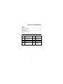
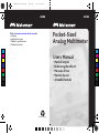
AM8BAM8B
Pocket-Sized
Analog Multimeter
Please Recycle
Visit www.metermantesttools.com for
• Catalog
• Application notes
• Product specifications
• Product manuals
Users Manual
• Mode d’emploi
• Bedienungshandbuch
•
• Manual de uso
• Anvandärhanbok
Manuale d’Uso
C
M
Y
CM
MY
CY
CMY
K
AM8 man_cover.pdf 12/2/05 12:16:58 PMAM8 man_cover.pdf 12/2/05 12:16:58 PM


AM8B
Pocket-Sized Analog Multimeter
Users Manual
• Mode d’emploi
• Bedienungshandbuch
• Manual d’Uso
• Manual de uso
• Anvandähanbok
PN 2542587
December 2005
©2005 Meterman Test Tools.
All rights reserved. Printed in China


AM8B
Pocket-Sized Analog Multimeter
Users Manual
• Mode d’emploi
• Bedienungshandbuch
• Manual d’Uso
• Manual de uso
• Anvandähanbok
PN 2542587
December 2005
©2005 Meterman Test Tools.
All rights reserved. Printed in China
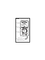
English

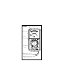
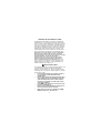
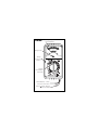
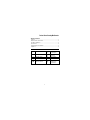
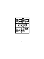
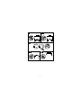
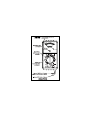
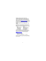
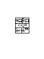
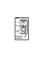
VA Input (Red). High input for
voltage resistance and current
0
60
120
180
240
300
4
0
2
0
1
0
5
4
3
2
1
.5
0
O
H
M
S
0
50
100
150
200
250
0
30
10
2
60
20
4
90
30
6
120
40
8
150
50
10
0
0
0
B
A
D
G
O
O
D
BAT
DCV.mA
AC10V
ACV
BAT
DCV.mA
AC10V
ACV
2K /VDC AC
100
200
500
AM8B
COM Input (Black) - common or
low input for all measurements
Analog needle display with mirror scale
Needle Zero Adjust
Resistance
Zero Adjust
Function/
Range/Off
Selector

1
Pocket-Sized Analog Multimeter
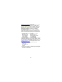
Contents
Symbols.........................................................................................1
Warnings and Precautions.............................................................2
Measuring Procedures...................................................................3
Specifications.................................................................................3
Battery / Fuse Replacement............................................................5
Repair.............................................................................................5
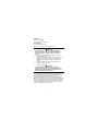
Symbols
B
Battery
W
Refer to the
manual
T
Double insulated
X
Dangerous
Voltage
F Direct Current J Earth Ground
B Alternating Current I Fuse
P
Complies with EU
directives >
Canadian
Standards
Association

2
Limited Warranty and Limitation of Liability
Your Meterman product will be free from defects in material and
workmanship for 1 year from the date of purchase. This warranty
does not cover fuses, disposable batteries or damage from accident,
neglect, misuse, alteration, contamination, or abnormal conditions
of operation or handling. Resellers are not authorized to extend any
other warranty on Meterman’s behalf. To obtain service during the
warranty period, return the product with proof of purchase to an
authorized Meterman Test Tools Service Center or to a Meterman
dealer or distributor. See Repair Section above for details. THIS
WARRANTY IS YOUR ONLY REMEDY. ALL OTHER WARRANTIES -
WHETHER EXPRESS, IMPLIED OR STAUTORY - INCLUDING
IMPLIED WARRANTIES OF FITNESS FOR A PARTICULAR PURPOSE
OR MERCHANTABILITY, ARE HEREBY DISCLAIMED.
MANUFACTURER SHALL NOT BE LIABLE FOR ANY SPECIAL,
INDIRECT, INCIDENTAL OR CONSEQUENTIAL DAMAGES OR
LOSSES, ARISING FROM ANY CAUSE OR THEORY. Since some
states or countries do not allow the exclusion or limitation of an
implied warranty or of incidental or consequential damages, this
limitation of liability may not apply to you.
WWarnings and Precautions
This instrument is EN61010-1 certified for Installation Category II. It
is recommended for use with local level power distribution,
appliances, portable equipment, etc, where only smaller transient
overvoltages may occur, and not for primary supply lines, overhead
lines and cable systems.
• Do not exceed the maximum overload limits per function
(see specifications) nor the limits marked on the
instrument itself.
• Exercise extreme caution when: measuring voltage >20V //
current >10mA // AC power line with inductive loads // AC
power line during electrical storms // current, when the
fuse blows in a circuit with open circuit voltage >300 V //
servicing CRT equipment.
• Inspect DMM, test leads and accessories before every use.
Do not use any damaged part.
• Never ground yourself when taking measurements. Do not
touch exposed circuit elements or probe tips.
• Always measure current in series with the load – NEVER
ACROSS a voltage source. Check fuse first.

3
• Never replace a fuse with one of a different rating.
• Do not operate instrument in an explosive atmosphere.
Measuring Procedures
Before You Start: Open the back of the unit and place one AA size
battery into the battery slot with correct polarity as shown. The
battery is used for resistance measurements only.
1. When connecting or disconnecting test leads to/from a
circuit, always first turn off power to device or circuit being
tested and discharge all capacitors.
2. Turn the function/range selector to the desired position. If
signal magnitude is unknown, always start with highest range
and scale down afterwards.
3. Strictly observe the max input limits. For the various
measurements, connect test lead tips as shown in
illustrations on page 7. As a last step read the measurement
result off the appropriate scale on the display.
Notes: For most accurate readings, keep the meter laying flat on a
non-metallic surface. Use a range setting that results in a reading in
the upper 1/3 of the meter scale. If the needle is not resting exactly
over the “0” at the left side of the scale, turn the plastic screw under
the display to adjust the needle.
Note for resistance measurements: Before taking a resistance
measurement, short the two probes together and adjust the
Resistance Zero Adjust knob to set the pointer to the “0” at the right
end of the resistance scale. If this does not prove possible, replace
battery.
Specifications
General Specifications
Display: Analog needle display with mirror scale.
Operating Temperature: 0°C to 50°C, 0 to 70% Relative Humidity
Storage Temperature: -20°C to 60°C, 0 to 80% RH with battery
removed from meter
Environment: Indoor use, altitude up to 2000m.
Power Supply (for resistance measurement): one AA size 1.5 V
battery
Dimensions, with Holster (H x W x D): 5.1 x 2.6 x 1.65 inches,
(13 x 6.6 x 4.2cm)
Weight (including battery): 6.7 ounces (176 grams)

4
Accessories: Test leads (attached), holster, battery, and Users
Manual.
Safety: Meets EN61010-1:2001 Cat II 300V; Pollution Degree II,
Class 2; UL311
EMC: Meets EN50081-1, EN50082-1
P EMC: This product complies with requirements of the
following European Community Directives: 89/336/EEC
(Electromagnetic Compatibility) and 73/23/EEC (Low Voltage) as
amended by 93/68/EEC (CE Marking).
However, electrical noise or intense electromagnetic fields in the
vicinity of the equipment may disturb the measurement circuit.
Measuring instruments will also respond to unwanted signals that
may be present within the measurement circuit. Users should
exercise care and take appropriate precautions to avoid misleading
results when making measurements in the presence of electronic
interference.
Electrical Specifications
Accuracies are indicated as ± % of full scale values at 23°C ± 5°C,
<75% RH.
DC Volts
Ranges: 2.5, 10, 50, 150, 300 V
Accuracy, all Ranges: ±5%
Input Impedance: 2 ke/V
AC Volts – Accuracies apply to sine wave inputs only
Ranges: 50, 150, 300 V
Accuracy, all ranges: ±5%
Input Impedance: 2 ke/V
DC Current
Ranges: 0.5, 10, 250 mA
Accuracy: ±5%
OL Protection: 200 mA/250 V ceramic fuse (PN FP150)
Resistance
Ranges: 5 ke, 500 ke
Accuracy, all ranges: ±5%
Battery Test
Battery Voltages: 1.5 V, 9 V
Accuracy: ±10% of good/bad line

5
Battery / Fuse Replacement
W Warning
To prevent electrical shock hazard, turn off the multimeter
and any device or circuit under test and disconnect the test
leads before removing the rear cover.
1. Remove the rear case by unscrewing the screws that secure
it to the front.
2. Fuse replacement: Remove the blown fuse (5 x 20mm) from
the fuse holder. Replace with a 200 mA/250 V quick acting
fuse (Meterman PN: FP150).
3. Battery replacement: Remove the 1.5 VDC AA battery and
replace with same.
4. Reassemble the instrument.
W Warning
Use of an incorrect fuse could result in serious injury or
even death. Failure to turn off the multimeter before
installing the battery could result in damage to instrument
and battery.
Repair
All test tools returned for warranty or non-warranty repair or for
calibration should be accompanied by the following: your name,
company’s name, address, telephone number, and proof of
purchase. Additionally, please include a brief description of the
problem or the service requested and include the test leads with the
meter. Non-warranty repair or replacement charges should be
remitted in the form of a check, a money order, credit card with
expiration date, or a purchase order made payable to Meterman Test
Tools.
In-Warranty Repairs and Replacement – All Countries
Please read the warranty statement and check your battery before
requesting repair. During the warranty period any defective test tool
can be returned to your Meterman Test Tools distributor for an
exchange for the same or like product. Please check the “Where to
Buy” section on
www.metermantesttools.com for a list of
distributors near you. Additionally, in the United States and Canada
In-Warranty repair and replacement units can also be sent to a
Meterman Test Tools Service Center (see below for address).

6
Non-Warranty Repairs and Replacement – US and Canada
Non-warranty repairs in the United States and Canada should be
sent to a Meterman Test Tools Service Center. Call Meterman Test
Tools or inquire at your point of purchase for current repair and
replacement rates.
In USA In Canada
Meterman Test Tools Meterman Test Tools
1420 75th Street SW 400 Britannia Rd. E. Unit #1
Everett, WA 98203 Mississauga, ON L4Z 1X9
Tel: 888-993-5853 Tel: 905-890-7600
Fax: 425-446-6390 Fax: 905-890-6866
Non-Warranty Repairs and Replacement – Europe
European non-warranty units can be replaced by your Meterman
Test Tools distributor for a nominal charge. Please check the
“Where to Buy” section on www.metermantesttools.com
for a list of
distributors near you.
European Correspondence Address*
Meterman Test Tools Europe
P.O. Box 1186 5602 BD Eindhoven
The Netherlands
*(Correspondence only – no repair or replacement available from
this address. European customers please contact your distributor.)

7
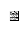
2
2
1
1
1
2
2
1
2
4
5
3
1
V
mA
V

8

AM8B
Pocket-Sized Analog Multimeter
Users Manual
• Mode d’emploi
• Bedienungshandbuch
• Manual d’Uso
• Manual de uso
• Anvandähanbok
French
Français

0
60
120
180
240
300
4
0
2
0
1
0
5
4
3
2
1
.5
0
O
H
M
S
0
50
100
150
200
250
0
30
10
2
60
20
4
90
30
6
120
40
8
150
50
10
0
0
0
B
A
D
G
O
O
D
BAT
DCV.mA
AC10V
ACV
2K /VDC AC
100
200
500
BAT
DCV.mA
AC10V
ACV
AM8B
Entrée COM (Noir) - commun
ou bas pour toutes mesures
Affichage à aiguille avec
mirroir antiparallaxe
Ajustage du zéro
Ajustage
du zéro pour
résistance
Sélecteur
fonctions/calibres/
marche-arrêt
Entrée V- (Rouge). Haut pour
tension et résistance

1
Pocket-Sized Analog Multimeter
Table des matières
Symboles ......................................................................................... 1
Avertissements et Précautions......................................................... 3
Procédures de Mesure..................................................................... 3
Spécifications................................................................................... 4
Remplacement Pile et Batterie ......................................................... 5
Réparation........................................................................................ 6
Symboles
B
Pile
W
Se reporter au
mode d’emploi
T
Double isolation
X
Tension
dangereuse
F Courant continu J Prise de terre
B Courant alternatif I Fusible
P
Conforme aux
directives de l’UE >
Association
canadienne de
normalisation

2
Limites de garantie et de responsabilité
Meterman garantit l’absence de vices de matériaux et de fabrication
de ce produit dans des conditions normales d’utilisation et
d’entretien pendant une période d’un an prenant effet à la date
d’achat. Cette garantie ne s’applique pas aux fusibles, aux piles
jetables ni à tout produit mal utilisé, modifié, contaminé, négligé ou
endommagé par accident ou soumis à des conditions anormales
d’utilisation et de manipulation. Les distributeurs agréés par
Meterman ne sont pas autorisés à appliquer une garantie plus
étendue au nom de Meterman. Pour bénéficier de la garantie,
renvoyez le produit accompagné d’un justificatif d’achat auprès d’un
centre de services agréé par Meterman Test ou du distributeur ou
du revendeur Meterman. Voir la section Réparation ci-dessus pour
tous les détails. LA PRESENTE GARANTIE EST LE SEUL ET
EXCLUSIF RECOURS TOUTES AUTRES GARANTIES, EXPLICITES,
IMPLICITES OU STATUTAIRES, NOTAMMENT LE CAS ECHEANT
LES GARANTIES DE QUALITE MARCHANDE OU D’ADAPTATION A
UN OBJECTIF PARTICULIER SONT EXCLUES PAR LES PRESENTES.
LE FABRICANT NE SERA EN AUCUN CAS TENU RESPONSABLE DE
DOMMAGES PARTICULIERS, INDIRECTS, ACCIDENTELS OU
CONSECUTIFS, NI D’AUCUNS DEGATS OU PERTES DE DONNEES,
SUR UNE BASE CONTRACTUELLE, EXTRA-CONTRACTUELLE OU
AUTRE. Etant donné que certains pays ou états n’admettent pas les
limitations d’une condition de garantie implicite, ou l’exclusion ou la
limitation de dégâts accidentels ou consécutifs, les limitations et les
exclusions de cette garantie ne s’appliquent pas obligatoirement à
chaque acheteur.

3
WAvertissements et Précautions
Cet instrument est certifié EN61010-1 pour catégorie d’installation
II. Son utilisation est conseillée pour des réseaux de distribution
locaux, les appareils électro-ménagers, les appareils portatifs, etc,
où seulement des transitoires d’un niveau peu élevé peuvent sur
venir, et non pour des réseaux de distribution à haute énergie.
• N’excédez jamais les limites de surcharge continue par
fonction (voir spécifications) ou d’autres limites marquées
sur l’appareil.
• Soyez très prudent quand vous mesurez: des tensions > 20
V // du courant > 10 mA // du courant de secteur avec
charge inductive ou par temps de tempête // du courant
quand le fusible saute dans un circuit avec tension en
circuit ouvert de > 300 V // en mesurant dans des appareils
à tube cathodique (transitoires à haute tension)
• Inspectez appareil, câbles, connecteurs avant chaque
mesure. N’utilisez pas des pièces endommagées
• Ne touchez pas les pointes de touche ou le circuit pendant
les mesures Isolez-vous !
• Pour la mesure de courant, connectez l’appareil en série
avec le circuit – JAMAIS en parallèle avec une source de
tension.
• Ne jamais installer un fusible de calibre différent
• N’utilisez-pas cet appareil dans des atmosphères
explosives.
Procédures de Mesure
Avant de commencer: Ouvrez l’appareil et placez une pile AA en
respectant la polarité. La pile sert uniquement à la mesure de
résistance
1. Avant de connecter ou de déconnecter les cordons de test,
coupez l’alimentation du circuit mesuré et déchargez les
condensateurs.
2. Placez le sélecteur sur la gamme/fonction désirée. Si la
magnitude du signal n’est pas connue, commencez par la
gamme la plus élevée, et diminuez ensuite jusqu’à obtenir
une bonne lecture.
3. Ne dépassez pas les limites d’entrée. Pour les diverses
mesures, connectez les pointes de touche comme illustré en
page 8. Lisez la mesure sur l’afficheur.

4
Notes: Pour des mesures précises, placez l’appareil horizontalement
sur une surface non-métallique. Sélectionnez une gamme où la
lecture se situe dans le tiers supérieur de l’échelle.
Si l’aiguille n’est pas exactement sur le « 0 » à l’extrémité gauche de
l’échelle, réglez-la en tournant la vis en plastique sous le cadran.
Note pour mesures de résistance: Avant d’effectuer une mesure de
résistance, reliez les deux sondes entre elles et tournez la molette de
tarage de résistance nulle pour que l’aiguille soit sur le « 0 » à
l’extrémité droite de l’échelle de résistance. Si vous n’y parvenez
pas, remplacez la pile.
Spécifications
Spécifications Générales
Afficheur: A aiguille, avec mirroir anti-parallaxe
Temp. de fonctionnement: 0 à 50°C, 0 à 70% H.R.
Temp. de stockage: -20°C à 60°C, 0 à 80% H.R., pile enlevée
Environnement : Utilisation à l'intérieur de locaux, altitude jusqu’à
2 000 m
Alimentation: Une pile 1.5V AA (pour mesure de résistance)
Dimensions, avec holster (H x L x P): 13 x 6.6 x 4.2 cm
Poids (avec pile): 176 g
Accessoires: Cordons de mesure (fixes), étui, pile et mode d’emploi.
Sécurité: Conforme à la norme EN61010-1:2001 Cat II 300V ; degré
2 de pollution, classe 2
EMC: selon EN50081-1, EN50082-1
P EMC: Ce produit est con-forme aux exigences des
directives suivantes de la Communauté Européenne: 89/336/EEC
(Compatibilité Electromagnétique) et 73/23/ EEC (Basse Tension),
modifiée par 93/68/EEC (CE Marking).
Cependant, du bruit électrique ou des champs électromagnétiques
intenses dans la proximité de l’instrument peuvent influencer le
circuit de mesure. L’instrument peut également être perturbé par
des signaux parasytes dans le circuit mesuré. L’utilisateur doit être
vigilant et prendre des précautions appropriées pour éviter des
résultats erronés quand les mesures sont prises en présence
d’interférences electro-magnétiques.
Sidan laddas...
Sidan laddas...
Sidan laddas...
Sidan laddas...
Sidan laddas...
Sidan laddas...
Sidan laddas...
Sidan laddas...
Sidan laddas...
Sidan laddas...
Sidan laddas...
Sidan laddas...
Sidan laddas...
Sidan laddas...
Sidan laddas...
Sidan laddas...
Sidan laddas...
Sidan laddas...
Sidan laddas...
Sidan laddas...
Sidan laddas...
Sidan laddas...
Sidan laddas...
Sidan laddas...
Sidan laddas...
Sidan laddas...
Sidan laddas...
Sidan laddas...
Sidan laddas...
Sidan laddas...
Sidan laddas...
Sidan laddas...
Sidan laddas...
Sidan laddas...
Sidan laddas...
Sidan laddas...
Sidan laddas...
Sidan laddas...
Sidan laddas...
Sidan laddas...
Sidan laddas...
Sidan laddas...
Sidan laddas...
Sidan laddas...
Sidan laddas...
-
 1
1
-
 2
2
-
 3
3
-
 4
4
-
 5
5
-
 6
6
-
 7
7
-
 8
8
-
 9
9
-
 10
10
-
 11
11
-
 12
12
-
 13
13
-
 14
14
-
 15
15
-
 16
16
-
 17
17
-
 18
18
-
 19
19
-
 20
20
-
 21
21
-
 22
22
-
 23
23
-
 24
24
-
 25
25
-
 26
26
-
 27
27
-
 28
28
-
 29
29
-
 30
30
-
 31
31
-
 32
32
-
 33
33
-
 34
34
-
 35
35
-
 36
36
-
 37
37
-
 38
38
-
 39
39
-
 40
40
-
 41
41
-
 42
42
-
 43
43
-
 44
44
-
 45
45
-
 46
46
-
 47
47
-
 48
48
-
 49
49
-
 50
50
-
 51
51
-
 52
52
-
 53
53
-
 54
54
-
 55
55
-
 56
56
-
 57
57
-
 58
58
-
 59
59
-
 60
60
-
 61
61
-
 62
62
-
 63
63
-
 64
64
-
 65
65


på andra språk
- italiano: Meterman AM8B Manuale utente
- español: Meterman AM8B Manual de usuario
- Deutsch: Meterman AM8B Benutzerhandbuch
- français: Meterman AM8B Manuel utilisateur
- English: Meterman AM8B User manual
Andra dokument
-
Amprobe AM8C Analog Multimeter Användarmanual
-
-
-
-
-
-
-
-
-