ABB Orion3 Extended Excerpts From The Original Instructions
- Kategori
- Bekvämlighetsbelysning
- Typ
- Excerpts From The Original Instructions
Denna manual är också lämplig för

ABB Jokab Safety Varlabergsvägen 11, SE-434 39 Kungsbacka, Sweden
www.abb.com/jokabsafety
Excerpts from the original instructions
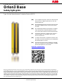
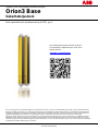
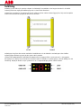
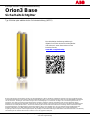
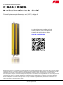
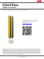
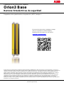
Orion3 Base
Safety light grids
Type 4 Active Opto-electronic Protective Device (AOPD)
While every effort has been taken to ensure the accuracy of information contained in this book and any associated promotional and information
material ABB Jokab Safety cannot accept responsibility for errors or omissions and reserves the right to make any improvements without notice. It is
the user’s responsibility to ensure that this equipment is correctly designed, specified, installed, cared for and operated to meet all applicable local,
national and international codes/regulations. Technical data in our book is correct to the level of accuracy of ABB Jokab Safety´s test procedures as
verified by various international approved bodies. Other information (such as application examples, wiring diagrams, operation or use) is intended
solely to illustrate the various uses of our products. ABB Jokab Safety does not guarantee or imply that the product when used in accordance with
such examples in a particular environment will fulfil any particular safety requirement and does not assume any responsibility or liability for actual
use of the product based on the examples given.
[EN] The complete instruction manual is delivered with
the product in a digital format and can also be
downloaded from:
[SE] Den fullständiga bruksanvisningen levereras med
produkten i digitalt format och kan även laddas
ned från:
[DE] Die vollständige Bedienungsanleitung in digitaler
Form wird mit dem Produkt geliefert und steht
auch unter dieser Adresse zum Download bereit:
[IT] Il manuale di istruzioni completo viene fornito in
formato digitale con il prodotto e può anche
essere scaricato da:
[FR] La notice d'instructions complète est fournie avec
le produit au format numérique et peut également
être téléchargée sur le site :
[ES] El manual de instrucciones completo se entrega
junto con el producto en formato digital y también
puede descargarse en este enlace:
www.abb.com/jokabsafety

2TLC172295M0201 Rev A 2 www.abb.com/jokabsafety
2015-03-20
Safety information
Warning! For a correct and safe use of the Orion3 Base light grids, the following points must be observed:
The stopping system of the machine must be electrically controlled.
This control system must be able to stop the hazardous movement of the machine within the total machine
stopping time T as per paragraph “Minimum installation distance” of the instruction manual, and during all
working cycle phases.
Mounting and connection of the AOPD must be carried out by qualified personnel only, according to the
indications included in the special sections of the instruction manual and in the applicable standards.
The AOPD must be securely placed in a particular position so that access to the hazard zone is not possible
without the interruption of the beams, see paragraph “Installation” of the instruction manual.
The personnel operating in the hazard zone must be well trained and must have adequate knowledge of all
the operating procedures of the AOPD.
The TEST button must be located outside the hazard zone because the operator must check the entire
hazard zone during all the test operations.
The RESET/ACKNOWLEDGE button must be located outside the hazard zone because the operator must
check the entire hazard zone during all reset/acknowledge operations. It must be impossible to reach the
button from the hazard zone.
Please carefully read the instructions for the correct functioning before powering the AOPD.
Installation
Warning! Make sure that the protection level assured by the AOPD is appropriate for the machine to be controlled,
see EN ISO 13849-1:2008.
The outputs (OSSD) of the AOPD must be used as machine stopping devices and not as command devices.
The machine must have its own Start command.
The dimension of the smallest object to be detected must be larger than the resolution of the AOPD.
The AOPD must be installed in a room complying with the technical characteristics indicated in paragraph
“Technical data” of the instruction manual.
Do not place the AOPD near strong and/or flashing light sources or similar devices.
Strong electromagnetic interferences can jeopardize the function of the AOPD. Please contact your
ABB Jokab Safety representative for advice.
The operating distance of the device can be reduced in presence of smog, fog or airborne dust.
A sudden change in environment temperature, with very low minimum peaks, can generate a small
condensation layer on the lenses and so jeopardize the function.
Reflecting surfaces placed near the light beams of the AOPD (over, under or laterally) can cause passive
reflections. These reflections can compromise the recognition of an object inside the detection zone.
The safety device must be positioned at a distance that prevents a person or part of a person to reach the
hazard zone before the hazardous motion of the machine has been stopped by the AOPD. See the instruction
manual for the calculation of this minimum installation distance.
Warning! The minimum installation distance must be respected. For more information about its calculation,please
refer to the instruction manual or EN ISO 13855:2010.
Warning! Make sure to test the function and to perform the checks described in paragraph “Checks after first
installation” of the instruction manual before machine start-up.

2TLC172295M0201 Rev A 3 www.abb.com/jokabsafety
2015-03-20
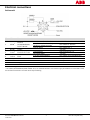
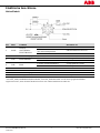
Electrical connections
Active unit
Pin
Wire
1
Function
Connection to
1
White
2
RESET/
ACKNOWLEDGE/
RESET MODE
Auto. Reset with no function
+24 VDC
Auto. Reset with Acknowledge
function or Alignment mode
NC contact to +24 VDC
Manual Reset
NC contact to 0 V
2
Brown
Supply
+24 VDC
3
Green
2
EDM SELECTION
Activate EDM
Not connected or 0 V
Deactivate EDM
+24 VDC
4
Yellow
EDM
Function used/activated
NC contact of force-guided relay
Function not used/deactivated
Not connected or 0 V
5
Grey
OSSD1
Safety control module for ex.
6
Pink
OSSD2
Safety control module for ex.
7
Blue
Supply
0 V
8
Red
Earth
Earth
1
Colors according to ABB Jokab Safety standard cables.
2
The “RESET/ACKNOWLEDGE/RESET MODE” wire, the “EDM SELECTION” wire and the supply wires MUST be connected in order
for the device to function. The other wires may be floating.

2TLC172295M0201 Rev A 4 www.abb.com/jokabsafety
2015-03-20
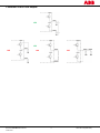
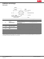
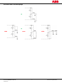
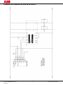
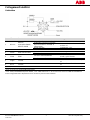
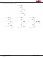
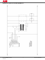
Connection example to a RT9 safety relay

2TLC172295M0201 Rev A 5 www.abb.com/jokabsafety
2015-03-20
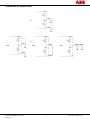
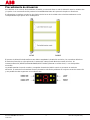
Connection of the OSSD outputs
YES
NO
NO
NO
YES

2TLC172295M0201 Rev A 6 www.abb.com/jokabsafety
2015-03-20
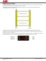
Alignment procedure
The alignment between the active and the passive unit is necessary to obtain the correct functioning of the AOPD. A
good alignment prevents outputs instability due to dust or vibration.
The alignment is perfect if the optical axes of the beams of the active unit coincide with the optical axes of the
corresponding mirrors on the passive unit.
The alignment is performed after having completed the mechanical installation and the electrical connections.
The Alignment mode is activated by pushing the external NC contact (RESET/ACKNOWLDGE/RESET MODE push-
button) for at least 0.5 s at power on.
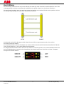
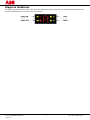
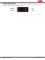
A display helps the user control and check the status of the AOPD, in Alignment mode, in normal operation mode and
when troubleshooting. The display consists in four LEDs and a 7-segment display on the active unit.

2TLC172295M0201 Rev A 7 www.abb.com/jokabsafety
2015-03-20
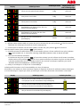
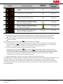
Display
Alignment status
Alignment
quality
Output status when
out of alignment
mode
First and last couple are not aligned
Bad
OSSD OFF
Last couple is not aligned
Bad
OSSD OFF
First couple is not aligned
Bad
OSSD OFF
Every couple over the lower light reception
threshold and no couple over the upper light
reception threshold
Good
OSSD ON
Every couple over the lower light reception
threshold and one couple over the upper
light reception threshold
OSSD ON
Every couple over the upper light reception
threshold
Excellent
OSSD ON
1 ) Keep the active unit in a steady position and adjust the passive unit until the yellow LED ( FIRST) turns off.
This condition shows the alignment of the first transmitter/receiver couple.
2 ) Rotate the passive unit, pivoting around the lower optics axis, until the yellow LED ( LAST) turns off.
NB: Make sure that the green LED ( ) is on and steady.
3 ) Slightly turn both units both ways to find the limits of the area in which the green LED ( ) is steady and “3” is
displayed (Maximum alignment). Place both units in the centre of this area.
4 ) Fix the two units firmly using brackets.
Check that the green LED ( ) on the active unit is on when the beams are not interrupted Then check that
the red LED ( ) turns on when one single beam is interrupted. This check shall be made with the special
cylindrical “Test Piece” having a suitable size for the resolution of the device used (see paragraph “Checks after
first installation” of the instruction manual).
5 ) Switch the device off and on to normal operating mode.
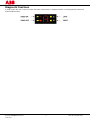
The alignment level is also monitored during normal operating mode and visualized on the display.
Once the AOPD has been aligned and correctly fastened, the signal on the display is useful both to check the
alignment and to show a change in the environmental conditions (presence of dust, light disturbance and so on). The
behaviour is summarized in the next table.
Display
Alignment status
Alignment quality
Every couple over the lower light reception threshold
and no couple over the upper light reception threshold
Min.
Every couple over the lower light reception threshold
and one couple over the upper light reception
threshold
Every couple over the upper light reception threshold
Excellent

2TLC172295M0201 Rev A 8 www.abb.com/jokabsafety
2015-03-20
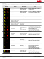
Diagnostic functions
A display helps the user control and check the status of the AOPD, in Alignment mode, in normal operation mode and
when troubleshooting.

2TLC172295M0201 Rev A 9 www.abb.com/jokabsafety
2015-03-20
Active unit
All the possible cases of visualization are explained in the table below except those relative to the Alignment mode
(see above).
Display
Status
Description
Action
Interlock
Detection zone free.
OSSD outputs off.
Push the RESET button to return to
normal operation.
Interlock
Beam(s) interrupted.
OSSD outputs off.
Remove the object from the detection
zone and push the RESET button.
OSSD ON
OSSD outputs on.
OSSD OFF
OSSD outputs off.
Normal operation mode,
OSSD OFF, interlock
EDM function activated.
Normal operation mode,
OSSD OFF, interlock
EDM function
deactivated.
Error mode
OSSD error, one or
both.
OSSD outputs off.
Check the wiring and connections of
the OSSD outputs. Make sure that
there is no short-circuit between them
or with the supply voltage.
Then Acknowledge.
If the error persists, contact your
ABB Jokab Safety representative.
Error mode
(critical)
Microprocessor error.
OSSD outputs off.
Turn AOPD off and on. If the error
persists, contact your
ABB Jokab Safety representative.
Error mode
Optical error.
OSSD outputs off.
Acknowledge the error. If the error
persists, contact your
ABB Jokab Safety representative.
Error mode
EDM error.
OSSD outputs off.
Check the wiring and the connections
of EDM SELECTION and EDM as well
as the time sequence (see the
instruction manual, Time chart).
Acknowledge the error.
If the error persists, contact your
ABB Jokab Safety representative.
AOPD OFF
Power supply error.
OSSD outputs off.
Check the wiring and connections of
the power supply. Check that its value
is within the allowed range.
If the error persists, contact your
ABB Jokab Safety representative.

2TLC172295M0201 Rev A 10 www.abb.com/jokabsafety
2015-03-20
Technical data
Manufacturer
Address
ABB JOKAB SAFETY
Varlabergsvägen 11
SE-434 39 Kungsbacka
Sweden
Electrical Data
Power supply:
+24 VDC 20%
Consumption, Active unit:
6.5 W max (without load)
Outputs
2 PNP
Short-circuit protection:
Output current:
Output voltage – ON:
Output voltage – OFF:
Capacitive load
1.4 A at 55°C
0.5 A max / output
Power supply value less 1 V (min.)
0.2 V max.
2.2 µF at +24 VDC
Response time:
From 11 to 24 ms. See paragraph “Model overview” of the
instruction manual
Electrical protection:
Class III - use SELV/PELV
Connections:
M12 - 8 poles
Cable length (for power supply):
70 m max.
Pollution degree:
2
Optical Data
Light source:
Infrared LED (950 nm)
Resolution:
See paragraph “Model overview” of the instruction manual
Protected height:
See paragraph “Model overview” of the instruction manual
Operating distance:
From 0.5 to 6.5 m or 8 m. See the instruction manual paragraph
12 – “Model overview”
Ambient light rejection:
According to IEC 61496-2:2013
Mechanical and environmental data
Operating temperature:
0…55°C
Storage temperature:
-25…+ 70 °C
Temperature class:
T6
Humidity:
15…95 % (no condensation)
Water protection grade:
IP65 (EN 60529:2000)
Vibrations:
Width 0.35 mm, Frequency,10…55 Hz
20 sweeps for each axis, 1 octave/min
(EN 60068-2-6:2008)
Shock resistance:
16 ms (10 G) 10
3
shocks per axis
(EN 60068-2-29:2008)
Housing material:
Painted aluminium (yellow RAL 1003)
Caps material:
PBT Valox 508
Front glass material:
PMMA
Weight, single unit without package:
Orion3-4-K1C-050-B
Orion3-4-K2C-080-B
Orion3-4-K2C-090-B
Orion3-4-K2C-120-B
Orion3-4-M1C-050 (passive)
Orion3-4-M2C-080 (passive)
Orion3-4-M2C-090 (passive)
Orion3-4-M2C-120 (passive)
1.3 Kg
1.8 Kg
2.1 Kg
2.6 Kg
1.2 Kg
1.7 Kg
1.9 Kg
2.5 Kg

2TLC172295M0201 Rev A 11 www.abb.com/jokabsafety
2015-03-20
Functional safety data
EN ISO 13849-1:2008
PL e, Cat 4
EN IEC 61508-1:2010
EN IEC 61508-2:2010
EN IEC 61508-3:2010
EN IEC 61508-4:2010
SIL 3
EN IEC 62061:2005/A1:2013
SIL CL 3
Prob. of Dangerous Failure/Hour (1/h)
PFH
d
9.28 ×10
-9
Life span (years)
T1
20
Mean Time to Dangerous Failure (years)
MTTF
d
463
Average Diagnostic Coverage
DC
96.00 %
Safe Failure Fraction
SFF
97.20 %
Hardware Fault Tolerance
HFT
1
EC Declaration of conformity
A copy of the EC Declaration of conformity can be found in the Instruction Manual and can also be downloaded from
www.abb.com/jokabsafety

ABB Jokab Safety Varlabergsvägen 11, SE-434 39 Kungsbacka, Sverige
www.abb.com/jokabsafety
Utdrag ur den ursprungliga bruksanvisningen
Orion3 Base
Säkerhetsljusbom
Aktiv optoelektronisk skyddsanordning (AOPD), typ 4
Även om allt gjorts för att säkerställa riktigheten av informationen i denna manual och eventuellt tillhörande kampanj- eller informationsmaterial,
frånsäger sig ABB Jokab Safety ansvar för fel eller försummelser och förbehåller sig rätten att göra ändringar och förbättringar utan föregående
meddelande. Det åligger användaren att säkerställa att utrustningen är korrekt konstruerad, specificerad, installerad, skött och hanterad för att
uppfylla alla tillämpliga lokala, nationella och internationella regler och föreskrifter. Tekniska data i denna manual är korrekta enligt
ABB Jokab Safetys testprocedurer som är kontrollerade av olika internationella godkända organ. Annan information (t.ex. applikationsexempel,
kopplingsscheman, drift eller användning) är endast avsedd att illustrera de olika användningsområdena för våra produkter. ABB Jokab Safety
utfärdar ingen garanti för att produkten uppfyller specifika säkerhetskrav om den används i de fall som anges ovan och tar inget ansvar för faktisk
användning av produkten utifrån de givna exemplen.
Den fullständiga bruksanvisningen levereras
med produkten i digitalt format och kan även
laddas ned från:
www.abb.com/jokabsafety

2TLC172295M3401 Rev A 2 www.abb.com/jokabsafety
2015-03-20
Säkerhetsinformation
Varning! Punkterna nedan ska följas för korrekt och säker användning av ljusbommarna Orion3 Base:
Maskinens stoppsystem ska vara elektriskt styrt.
Detta styrsystem ska kunna stoppa farliga rörelser hos maskinen inom den totala stopptiden för maskinen T
enligt avsnittet ”Min. installationsavstånd” i bruksanvisningen, samt i alla faser av arbetscykeln.
Montering och anslutning av AOPD:en får endast utföras av kvalificerad personal enligt de anvisningar som
finns i de särskilda avsnitten i bruksanvisningen och i tillämpliga standarder.
AOPD:en ska placeras på en särskild position så att det inte går att nå riskzonen utan att bryta strålarna (se
avsnittet ”Installation” i bruksanvisningen).
Personal som arbetar i riskzonen ska vara utbildade och ha adekvat kunskap om AOPD:ens driftförlopp.
TEST-knappen ska vara placerad utanför riskzonen eftersom operatören ska kontrollera hela riskzonen under
alla testkörningar.
TEST/ÅTERSTÄLLNINGS-knappen ska vara placerad utanför riskzonen eftersom operatören ska kontrollera
hela riskzonen under alla testkörningar och återställningar. Det ska vara omöjligt att nå knappen från
riskzonen.
Läs instruktionerna för korrekt funktion noga innan AOPD:en startas.
Installation
Varning! Se till att AOPD:ens angivna skyddsnivå är lämplig för styrning av maskinen, se EN ISO 13849-1:2008.
Utgångarna (OSSD) på AOPD:en ska användas för att stoppa maskinen och inte för manövrering. Maskinen
ska ha ett eget startkommando.
Måttet för det minsta föremålet som ska detekteras ska vara större än upplösningen för AOPD:en.
AOPD:en ska installeras i ett utrymme som uppfyller de tekniska specifikationer som anges i avsnittet
”Tekniska specifikationer” i bruksanvisningen.
Placera inte AOPD:en nära kraftiga och/eller blinkande ljuskällor eller liknande anordningar.
Kraftiga elektromagnetiska störningar kan störa AOPD:ens funktion. Kontakta din representant för
ABB Jokab Safety för rådgivning.
Anordningens arbetsräckvidd kan reduceras av rök, dimma eller luftburet damm.
En plötslig förändring i omgivningstemperaturen med mycket låga minimitoppar kan orsaka ett kondenslager
på linserna och störa funktionen.
Reflekterande ytor nära AOPD:ens strålar (över, under eller vid sidan) kan orsaka passiva reflektioner. Dessa
reflektioner kan påverka detektering av föremål i detekteringszonen.
Skyddsanordningen ska placeras på ett avstånd som förhindrar att en person eller kroppsdel når riskzonen
innan maskinens farliga rörelse har stoppats av AOPD:en. Se bruksanvisningen för att beräkna min.
installationsavstånd.
Varning! Min. installationsavstånd måste följas. För mer information om denna beräkning, se bruksanvisningen eller
EN ISO 13855:2010.
Varning! Se till att testa funktionen och utföra de kontroller som beskrivs i avsnittet ”Kontroller efter första
installationen” i bruksanvisningen innan maskinen startas.

2TLC172295M3401 Rev A 3 www.abb.com/jokabsafety
2015-03-20
Elektriska anslutningar
Aktiv enhet
Stift
Ledare
1
Funktion
Anslutning till
1
Vit
2
RESET/
ACKNOWLEDGE/
RESET MODE
Auto. Återställning utan funktion
+24 VDC
Auto. Återställning med
bekräftelsefunktion eller
inriktningsläge
NC-kontakt till +24 VDC
Manuell återställning
NC-kontakt till 0 V
2
Brun
Spänningsförsörjning
+24 VDC
3
Grön
2
EDM SELECTION
Aktivera EDM
Ej inkopplad eller 0 V
Inaktivera EDM
+24 VDC
4
Gul
EDM
Funktion använd/aktiverad
NC-kontakt från tvångsstyrt relä
Funktion ej använd/inaktiverad
Ej inkopplad eller 0 V
5
Grå
OSSD1
T.ex. säkerhetsmodul
6
Rosa
OSSD2
T.ex. säkerhetsmodul
7
Blå
Spänningsförsörjning
0 V
8
Röd
Jord
Jord
1
Färger enligt ABB Jokab Safetys standardkablar.
2
RESET/ACKNOWLEDGE/RESET MODE-ledaren, EDM SELECTION-ledaren och försörjningsledarna MÅSTE vara anslutna för att
anordningen ska fungera. Övriga ledare kan vara flytande.

2TLC172295M3401 Rev A 4 www.abb.com/jokabsafety
2015-03-20
Exempel på anslutning till ett RT9 säkerhetsrelä

2TLC172295M3401 Rev A 5 www.abb.com/jokabsafety
2015-03-20
Anslutning för OSSD-utgångar
JA
NEJ
NEJ
NEJ
JA

2TLC172295M3401 Rev A 6 www.abb.com/jokabsafety
2015-03-20
Inriktning
Inriktning av den aktiva och passiva enheten är nödvändig för att AOPD:en ska fungera korrekt. En väl utförd
inriktning förhindrar utgångsinstabilitet på grund av damm eller vibrationer.
Inriktningen är perfekt om de optiska axlarna för strålarna på den aktiva enheten ligger på en linje med de optiska
axlarna för motsvarande speglar på den passiva enheten.
Inriktningen ska göras efter att den mekaniska installationen och de elektriska anslutningarna har slutförts.
Inriktningsläget aktiveras genom att den externa NC-kontakten
(ÅTERSTÄLLNING/BEKRÄFTA/ÅTERSTÄLLNINGSLÄGE-knappen) hålls in under minst 0,5 s vid uppstart.
Med hjälp av en display kan användaren kontrollera status för AOPD:en i inriktningsläge, normalt driftläge och vid
felsökning. Displayen består av fyra lysdioder och en 7-segmentsdisplay på den aktiva enheten.

2TLC172295M3401 Rev A 7 www.abb.com/jokabsafety
2015-03-20
Display
Inriktningsstatus
Inriktningskvalitet
Utgångsstatus om
inte i inriktningsläge
Första och sista paret är inte inriktade
Dålig
OSSD AV
Sista paret är inte inriktat
Dålig
OSSD AV
Första paret är inte inriktat
Dålig
OSSD AV
Alla par över den nedre tröskeln för
ljusmottagning och inget par över den övre
tröskeln för ljusmottagning
God
OSSD PÅ
Alla par över den nedre tröskeln för
ljusmottagning och ett par över den övre
tröskeln för ljusmottagning
OSSD PÅ
Alla par över den övre tröskeln för
ljusmottagning
Perfekt
OSSD PÅ
1 ) Håll den aktiva enheten stabilt och justera den passiva enheten tills den gula lysdioden ( FÖRSTA) slocknar.
Tillståndet visar inriktningen för det första sändar-/mottagarparet.
2 ) Vrid den passiva enheten runt den nedre optikens axel tills den gula lysdioden ( SISTA) slocknar.
OBS! Kontrollera att den gröna lysdioden ( ) lyser konstant.
3 ) Vrid båda enheterna åt båda håll lite grann för att fastställa gränserna för det område där den gröna lysdioden
( ) lyser konstant och ”3” visas (max. inriktning). Ställ båda enheterna i mitten av det här området.
4 ) Fixera de två enheterna med fästen.
Kontrollera att den gröna lysdioden ( ) på den aktiva enheten lyser när strålarna inte är brutna. Kontrollera
därefter att den röda lysdioden ( ) tänds när en enstaka stråle bryts. Kontrollen ska göras med det speciella
cylindriska testföremålet som har en lämplig storlek för den använda anordningens upplösning (se avsnitt
”Kontroller efter första installationen” i bruksanvisningen).
5 ) Stäng av anordningen och slå på den i normalt driftläge.
Inriktningsnivån övervakas också i normalt driftläge och visas på displayen.
När AOPD:en har inriktats och fästs korrekt kan signalen på displayen användas för att både kontrollera inriktningen
och visa förändringar i omgivningen (damm, ljusstörningar och liknande). Beteendet sammanfattas i nästa tabell.
Display
Inriktningsstatus
Inriktningskvalitet
Alla par över den nedre tröskeln för ljusmottagning
och inget par över den övre tröskeln för ljusmottagning
Min.
Alla par över den nedre tröskeln för ljusmottagning
och ett par över den övre tröskeln för ljusmottagning
Alla par över den övre tröskeln för ljusmottagning
Perfekt

2TLC172295M3401 Rev A 8 www.abb.com/jokabsafety
2015-03-20
Diagnosfunktioner
Med hjälp av en display kan användaren kontrollera status för AOPD:en i inriktningsläge, normalt driftläge och vid
felsökning.

2TLC172295M3401 Rev A 9 www.abb.com/jokabsafety
2015-03-20
Aktiv enhet
Alla typer av visualiseringar förklaras i tabellen nedan förutom de som gäller inriktningsläge (se ovan).
Display
Status
Beskrivning
Åtgärd
Förreglering
Detekteringszon fri.
OSSD-utgångar AV.
Tryck på ÅTERSTÄLLNINGS-
knappen för att återgå till normal drift.
Förreglering
Stråle eller strålar brutna.
OSSD-utgångar AV.
Ta bort föremålet från
detekteringszonen och tryck på
ÅTERSTÄLLNINGS-knappen.
OSSD PÅ
OSSD-utgångar PÅ.
OSSD AV
OSSD-utgångar AV.
Normalt driftläge,
OSSD AV, förregling
EDM-funktion aktiverad.
Normalt driftläge,
OSSD AV, förregling
EDM-funktion
inaktiverad.
Felläge
OSSD-fel, en eller båda.
OSSD-utgångar AV.
Kontrollera kablarna och
anslutningarna för OSSD-utgångarna.
Kontrollera att de inte är kortslutna
sinsemellan eller med
försörjningsspänning.
Bekräfta därefter.
Kontakta din representant för
ABB Jokab Safety om felet består.
Felläge
(kritiskt)
Mikroprocessorfel.
OSSD-utgångar AV.
Stäng av och slå på AOPD:en.
Kontakta din representant för
ABB Jokab Safety om felet består.
Felläge
Optiskt fel.
OSSD-utgångar AV.
Bekräfta felet. Kontakta din
representant för ABB Jokab Safety
om felet består.
Felläge
EDM-fel.
OSSD-utgångar AV.
Kontrollera kablarna och
anslutningarna för EDM SELECTION
och EDM samt tidssekvensen (se
tiddiagrammet i bruksanvisningen).
Bekräfta felet.
Kontakta din representant för
ABB Jokab Safety om felet består.
AOPD AV
Spänningsförsörjningsfel.
OSSD-utgångar AV.
Kontrollera kablarna och
anslutningarna för
spänningsförsörjningen. Kontrollera
att värdet är inom tillåtet område.
Kontakta din representant för
ABB Jokab Safety om felet består.
Sidan laddas...
Sidan laddas...
Sidan laddas...
Sidan laddas...
Sidan laddas...
Sidan laddas...
Sidan laddas...
Sidan laddas...
Sidan laddas...
Sidan laddas...
Sidan laddas...
Sidan laddas...
Sidan laddas...
Sidan laddas...
Sidan laddas...
Sidan laddas...
Sidan laddas...
Sidan laddas...
Sidan laddas...
Sidan laddas...
Sidan laddas...
Sidan laddas...
Sidan laddas...
Sidan laddas...
Sidan laddas...
Sidan laddas...
Sidan laddas...
Sidan laddas...
Sidan laddas...
Sidan laddas...
Sidan laddas...
Sidan laddas...
Sidan laddas...
Sidan laddas...
Sidan laddas...
Sidan laddas...
Sidan laddas...
Sidan laddas...
Sidan laddas...
Sidan laddas...
Sidan laddas...
Sidan laddas...
Sidan laddas...
Sidan laddas...
Sidan laddas...
Sidan laddas...
Sidan laddas...
Sidan laddas...
Sidan laddas...
-
 1
1
-
 2
2
-
 3
3
-
 4
4
-
 5
5
-
 6
6
-
 7
7
-
 8
8
-
 9
9
-
 10
10
-
 11
11
-
 12
12
-
 13
13
-
 14
14
-
 15
15
-
 16
16
-
 17
17
-
 18
18
-
 19
19
-
 20
20
-
 21
21
-
 22
22
-
 23
23
-
 24
24
-
 25
25
-
 26
26
-
 27
27
-
 28
28
-
 29
29
-
 30
30
-
 31
31
-
 32
32
-
 33
33
-
 34
34
-
 35
35
-
 36
36
-
 37
37
-
 38
38
-
 39
39
-
 40
40
-
 41
41
-
 42
42
-
 43
43
-
 44
44
-
 45
45
-
 46
46
-
 47
47
-
 48
48
-
 49
49
-
 50
50
-
 51
51
-
 52
52
-
 53
53
-
 54
54
-
 55
55
-
 56
56
-
 57
57
-
 58
58
-
 59
59
-
 60
60
-
 61
61
-
 62
62
-
 63
63
-
 64
64
-
 65
65
-
 66
66
-
 67
67
-
 68
68
-
 69
69


ABB Orion3 Extended Excerpts From The Original Instructions
- Kategori
- Bekvämlighetsbelysning
- Typ
- Excerpts From The Original Instructions
- Denna manual är också lämplig för
på andra språk
- italiano: ABB Orion3 Extended
- español: ABB Orion3 Extended
- Deutsch: ABB Orion3 Extended
- français: ABB Orion3 Extended
- English: ABB Orion3 Extended
Relaterade papper
Andra dokument
-
SICK Relay Module UE10-2OS Bruksanvisningar
-
-
-
-
-
-
-
IFM GI712S Bruksanvisningar
-
CARLO GAVAZZI BSE-MAG Installationsguide
-