ABB Orion3 Extended Excerpts From The Original Instructions
- Kategori
- Bekvämlighetsbelysning
- Typ
- Excerpts From The Original Instructions

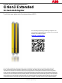
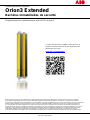
Excerpts from the original instructions
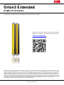
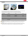
Orion3 Extended
Safety light grids
Type 4 Active Opto-electronic Protective Device (AOPD)
While every effort has been taken to ensure the accuracy of information contained in this book and any associated promotional and information
material ABB Jokab Safety cannot accept responsibility for errors or omissions and reserves the right to make any improvements without notice. It is
the user’s responsibility to ensure that this equipment is correctly designed, specified, installed, cared for and operated to meet all applicable local,
national and international codes/regulations. Technical data in our book is correct to the level of accuracy of ABB Jokab Safety´s test procedures as
verified by various international approved bodies. Other information (such as application examples, wiring diagrams, operation or use) is intended
solely to illustrate the various uses of our products. ABB Jokab Safety does not guarantee or imply that the product when used in accordance with
such examples in a particular environment will fulfil any particular safety requirement and does not assume any responsibility or liability for actual
use of the product based on the examples given.
[EN] The complete instruction manual is delivered with
the product in a digital format and can also be
downloaded from:
[SE] Den fullständiga bruksanvisningen levereras med
produkten i digitalt format och kan även laddas
ned från:
[DE] Die vollständige Bedienungsanleitung in digitaler
Form wird mit dem Produkt geliefert und steht
auch unter dieser Adresse zum Download bereit:
[IT] Il manuale di istruzioni completo viene fornito in
formato digitale con il prodotto e può anche
essere scaricato da:
[FR] La notice d'instructions complète est fournie avec
le produit au format numérique et peut également
être téléchargée sur le site :
[ES] El manual de instrucciones completo se entrega
junto con el producto en formato digital y también
puede descargarse en este enlace:
www.abb.com/jokabsafety
ABB Jokab Safety Varlabergsvägen 11, SE-434 39 Kungsbacka, Sweden
www.abb.com/jokabsafety

Safety information
Warning! For a correct and safe use of the Orion3 Extended light grids, the following points must be observed:
• The stopping system of the machine must be electrically controlled.
• This control system must be able to stop the hazardous movement of the machine within the total machine
stopping time T as per paragraph “Minimum installation distance” of the instruction manual, and during all
working cycle phases.
• Mounting and connection of the AOPD must be carried out by qualified personnel only, according to the
indications included in the special sections of the instruction manual and in the applicable standards.
• The AOPD must be securely placed in a particular position so that access to the hazard zone is not possible
without the interruption of the beams, see paragraph “Installation” of the instruction manual.
• The personnel operating in the hazard zone must be well trained and must have adequate knowledge of all
the operating procedures of the AOPD.
• The RESET button must be located outside the hazard zone because the operator must check the entire
hazard zone during all the reset and override operations. It must be impossible to reach the button from the
hazard zone.
• The external lamp signaling that muting is active must be visible from all operating sides.
• Please carefully respect the mounting instructions for the muting sensors, see paragraph “Muting” of the
instruction manual.
• If the external device monitoring (EDM) function is to be used, it must be activated with the dip-switches.
Please carefully read the instructions for the correct functioning before powering the AOPD.
2TLC172298M0201 2 www.abb.com/jokabsafety
2015-09-15

Installation
• The outputs (OSSD) of the AOPD must be used as machine stopping devices and not as command devices.
The machine must have its own Start command.
• The dimension of the smallest object to be detected must be larger than the resolution of the AOPD.
• The AOPD must be installed in a room complying with the technical characteristics indicated in paragraph
“Technical data” of the instruction manual.
• Do not place the AOPD near strong and/or flashing light sources or similar devices.
• Strong electromagnetic interferences can jeopardize the function of the AOPD. Please contact your
ABB Jokab Safety representative for advice.
• The operating distance of the device can be reduced in presence of smog, fog or airborne dust.
• A sudden change in environment temperature, with very low minimum peaks, can generate a small
condensation layer on the lenses and so jeopardize the function.
• Reflecting surfaces placed near the light beams of the AOPD (over, under or laterally) can cause passive
reflections. These reflections can compromise the recognition of an object inside the detection zone.
• The Muting/Override function is signaled by a muting/override lamp. Make sure that the lamp has sufficient
lighting and is visibly positioned near the hazard zone.
• Make sure to correctly use the muting sensors as described in paragraph “Muting” of the instruction manual.
• Avoid incongruent connections that cannot be controlled and thus, exclude undesired potentially dangerous
activations.
Warning! The minimum installation distance must be respected. For more information about its calculation,please
refer to the instruction manual or EN ISO 13855:2010.
Warning! Make sure to test the function and to perform the checks described in paragraph “Checks after first
installation” of the instruction manual before machine start-up.
2TLC172298M0201 3 www.abb.com/jokabsafety
2015-09-15

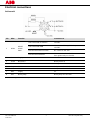
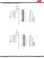
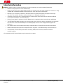
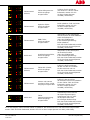
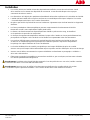
Electrical connections
Active unit
Pin Wire
1
Function Connection to
1 White
RESET
ACKN.
EDM
Auto. Reset with no function +24 VDC
Auto. Reset with EDM
NC contact of force-guided relay to
+24 VDC
Manual Reset with no function NC contact to +24 VDC
Manual Reset with EDM
NC contact in series with NC contact of
force-guided relay to +24 VDC
2 Brown Supply +24 VDC
3 Green MUTING A Muting sensor A
4 Yellow MUTING B Muting sensor B
5 Grey OSSD1 Safety control module for ex.
6 Pink OSSD2 Safety control module for ex.
7 Blue Supply 0 V
8 Red Muting lamp Muting lamp and +24 VDC
1
Colors according to ABB Jokab Safety standard cables.
2TLC172298M0201 4 www.abb.com/jokabsafety
2015-09-15

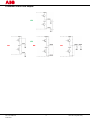
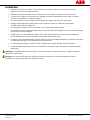
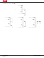
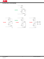
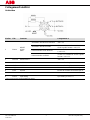
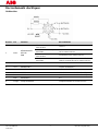
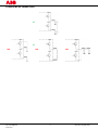
Connection example to a RT9 safety relay
2TLC172298M0201 5 www.abb.com/jokabsafety
2015-09-15

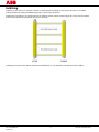
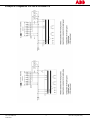
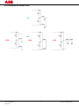
Connection of the OSSD outputs
YES
NO
NO
NO
YES
2TLC172298M0201 6 www.abb.com/jokabsafety
2015-09-15

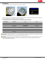
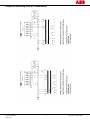
Functions
Unscrew the cap on top of the active unit to access the dip-switches.
1 2 3 4 5 6 7 8
1 2 3 4 5 6 7 8
NB: Each function is associated with two different dip-switches: the top and bottom dip-switches must be configured in
the same manner. The “ON” position is the position at delivery.
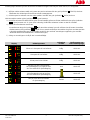
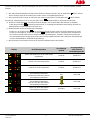
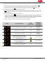
The dip-switches allows to set the functions as described in the following table:
Dip-switches Function ON* OFF
1 Muting timeout
10 min
∞
2 T / X or L-muting
T / X-muting
L-muting
3 Muting filter
Deactivated
Activated
4 Reset of the Override
Manual
Automatic
5 Not used
-
-
6 EDM
Deactivated
Activated
7 Reset
Automatic
Manual
8 Not used
-
-
*Factory default configuration
Warning! An infinite muting (timeout = ∞) is not compliant with EN 61496-1:2013. Therefore, all possible risks must be
considered and related precautions undertaken before selecting the option “∞”.
Warning! The device does not accept configuration changes during normal operation. A change is taken into account
after the next powering of the device. Therefore, the management and the use of the configuration dip-switches
should be performed with great care.
2TLC172298M0201 7 www.abb.com/jokabsafety
2015-09-15

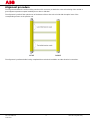
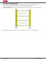
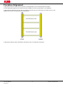
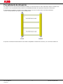
Alignment procedure
The alignment between the active and the passive unit is necessary to obtain the correct functioning of the AOPD. A
good alignment prevents outputs instability due to dust or vibration.
The alignment is perfect if the optical axes of the beams of the active unit coincide with the optical axes of the
corresponding mirrors on the passive unit.
The alignment is performed after having completed the mechanical installation and the electrical connections.
2TLC172298M0201 8 www.abb.com/jokabsafety
2015-09-15

The Alignment mode is activated by pushing the RESET push-button for at least 0.5 s at power on.
1 ) Keep the active unit in a steady position and adjust the passive unit until the yellow LED ( FIRST) turns off.
This condition shows the alignment of the first transmitter/receiver couple.
2 ) Rotate the passive unit, pivoting around the lower optics axis, until the yellow LED ( LAST) turns off.
NB: Make sure that the green LED ( ) is on and steady.
3 ) Slightly turn both units both ways to find the limits of the area in which the green LED ( ) is steady and “3” is
displayed (Maximum alignment). Place both units in the center of this area.
4 ) Fix the two units firmly using brackets.
Check that the green LED ( ) on the active unit is on when the beams are not interrupted Then check that
the red LED ( ) turns on when one single beam is interrupted. This check shall be made with the special
cylindrical “Test Piece” having a suitable size for the resolution of the device used (see paragraph “Checks after
first installation” of the instruction manual).
5 ) Switch the device off and on to normal operating mode.
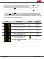
Display Alignment status
Alignment
quality
Output status when
out of alignment
mode
First and last couple are not aligned Bad OSSD OFF
Last couple is not aligned Bad OSSD OFF
First couple is not aligned Bad OSSD OFF
Every couple over the lower light reception
threshold and no couple over the upper
light reception threshold
Good
OSSD ON
Every couple over the lower light reception
threshold and one couple over the upper
light reception threshold
OSSD ON
Every couple over the upper light reception
threshold
Excellent OSSD ON
2TLC172298M0201 9 www.abb.com/jokabsafety
2015-09-15

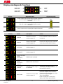
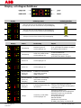
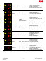
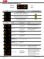
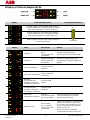
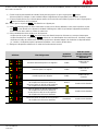
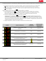
Display and diagnostic functions
Display Alignment status Alignment quality
Every couple over the lower light reception threshold
and no couple over the upper light reception
threshold
Min.
Every couple over the lower light reception threshold
and one couple over the upper light reception
threshold
Every couple over the upper light reception threshold Excellent
Display Status Description Action
Interlock
Detection zone free.
OSSD outputs off.
Push the RESET button to return to
OSSD ON.
Interlock
Beam(s) interrupted.
OSSD outputs off.
Remove the object from the detection
zone and push the RESET button.
OSSD ON OSSD outputs on.
OSSD OFF OSSD outputs off.
Normal operation
mode,
OSSD OFF,
interlock
EDM function activated.
Normal operation
mode,
OSSD OFF,
interlock
EDM function deactivated.
OSSD OFF,
interlock
Override function ready to
be activated
Activate the Override function
according to paragraph “Override” of
the instruction manual.
Error mode
OSSD error, one or both.
OSSD outputs off.
Check the wiring and connections of
the OSSD outputs. Make sure that
there is no short-circuit between them
or with the supply voltage.
Then Acknowledge.
If the error persists, contact your
ABB Jokab Safety representative.
2TLC172298M0201 10 www.abb.com/jokabsafety
2015-09-15

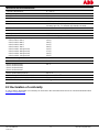
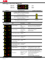
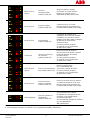
Error mode
(critical)
Microprocessor error.
OSSD outputs off.
Turn AOPD off and on. If the error
persists, contact your
ABB Jokab Safety representative.
Error mode
Optical error.
OSSD outputs off.
Acknowledge the error. If the error
persists, contact your
ABB Jokab Safety representative.
Error mode
EDM error.
OSSD outputs off.
Check the wiring and the
connections of EDM SELECTION
and EDM as well as the time
sequence (see the Time chart in the
instruction manual).
Acknowledge the error.
If the error persists, contact your
ABB Jokab Safety representative.
OSSD OFF
Override sequence error,
OSSD outputs off
Check the time sequence of the
Override function (see the Time
chart in the instruction manual).
If the error persists, contact your
ABB Jokab Safety representative
Error mode
(critical)
Dip switch error,
OSSD outputs off
Check the settings of the dip-
switches and turn the AOPD on and
off.
If the error persists, contact your
ABB Jokab Safety representative.
Error mode
Internal and external lamp
error, OSSD outputs off
Check the connection of the external
lamp and acknowledge. If the error
persists, contact your
ABB Jokab Safety representative
AOPD OFF
Power supply error.
OSSD outputs off.
Check the wiring and connections of
the power supply. Check that its value
is within the allowed range.
If the error persists, contact your
ABB Jokab Safety representative.
It is not possible to acknowledge a critical error. The device must be switched off and on. If the error persists, contact
your ABB Jokab Safety representative.
2TLC172298M0201 11 www.abb.com/jokabsafety
2015-09-15

Technical data
Manufacturer
Address ABB JOKAB SAFETY
Varlabergsvägen 11
SE-434 39 Kungsbacka, Sweden
Electrical data
Power supply:
+24 VDC ± 20 %
Active unit consumption (RX): 2.5 W max (normal operation without load)
Outputs: 2 PNP
Short-circuit protection: 1.4 A max at 55 °C
Output current 0.5 A max / output
Output voltage – status ON: Power supply value less 1 V
Output voltage – status OFF 0.2 V
Capacitive load 2.2 µF at +24 VDC max
Current for external lamp: 20 mA min, 250 mA max
Response times: From 11 to 12 ms. See paragraph 12 of the instruction manual
Protected height: From 500 mm to1200 mm. See paragraph 12 of the
instruction manual.
Electrical protection: Class III - use SELV/PELV
Connections: M12-8 poles male connector
Cables length (for power supply): 70 m. max
Pollution degree 2
Optical data
Emitting light (λ): Infrared, LED (860 nm)
Resolution: See paragraph 12 of the instruction manual.
Operating distance: From 0.5 to 8 m. See paragraph 12 of the instruction manual
Ambient light rejection: According to IEC-61496-2:2013
2TLC172298M0201 12 www.abb.com/jokabsafety
2015-09-15

Mechanical and environmental data
Operating temperature: 0…+ 55 °C
Storage temperature:
- 25…+ 70 °C
Temperature class: T6
Humidity: 15…95 % (no condensation)
Protection class: IP65 (EN 60529:2000)
Vibrations: Width 0.35 mm, Frequency 10 … 55 Hz
20 sweep per axis, 1 octave/min (EN 60068-2-6:2008)
Shock resistance: 16 ms (10 G) 10
3
shocks per axis (EN 60068-2-29: 2008)
Housing material: Painted aluminum (yellow RAL 1003)
Front glass material: PMMA
Caps material: PBT Valox 508 (grey RAL 7035)
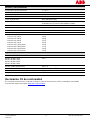
Weight, single unit without package:
Orion3-4-K1C-050-E
Orion3-4-K2C-080-E
Orion3-4-K2C-090-E
Orion3-4-K2C-120-E
Orion3-4-M1C-050 (passive)
Orion3-4-M2C-080 (passive)
Orion3-4-M2C-090 (passive)
Orion3-4-M2C-120 (passive)
1.3 Kg
1.8 Kg
2.1 Kg
2.6 Kg
1.2 Kg
1.7 Kg
1.9 Kg
2.5 Kg
Functional safety data
EN ISO 13849-1:2008 PL e, Cat 4
EN IEC 61508-1:2010,
EN IEC 61508-2:2010,
EN IEC 61508-3:2010,
EN IEC 61508-4:2010
SIL 3
EN IEC 62061:2005/A1:2013 SIL CL 3
Prob. of Dangerous Failure/Hour (1/h) PFH
d
8.57x10
-9
Life span (years) T1 20
Mean Time to Dangerous Failure (years) MTTF
d
439
EC Declaration of conformity
A copy of the EC Declaration of conformity can be found in the Instruction Manual and can also be downloaded from
www.abb.com/jokabsafety
2TLC172298M0201 13 www.abb.com/jokabsafety
2015-09-15

Utdrag ur den ursprungliga bruksanvisningen
Orion3 Extended
Säkerhetsljusbom
Aktiv optoelektronisk skyddsanordning (AOPD), typ 4
Även om allt gjorts för att säkerställa riktigheten hos informationen i denna manual och eventuellt tillhörande kampanj- eller informationsmaterial,
frånsäger sig ABB Jokab Safety ansvar för fel eller försummelser och förbehåller sig rätten att göra ändringar och förbättringar utan föregående
meddelande. Det åligger användaren att säkerställa att utrustningen är korrekt konstruerad, specificerad, installerad, skött och hanterad för att
uppfylla alla tillämpliga lokala, nationella och internationella regler och föreskrifter Tekniska data i denna manual är korrekta enligt
ABB Jokab Safetys testprocedurer som är kontrollerade av olika internationella godkända organ. Annan information (t.ex. applikationsexempel,
kopplingsscheman, drift eller användning) är endast avsedd att illustrera de olika användningsområdena för våra produkter. ABB Jokab Safety
utfärdar ingen garanti för att produkten uppfyller specifika säkerhetskrav om den används i de fall som anges ovan och tar inget ansvar för faktisk
användning av produkten utifrån de givna exemplen.
Den fullständiga bruksanvisningen levereras
med produkten i digitalt format och kan även laddas ned
från:
www.abb.com/jokabsafety
ABB Jokab Safety Varlabergsvägen 11, SE-434 39 Kungsbacka, Sverige
www.abb.com/jokabsafety

Säkerhetsinformation
Varning! Punkterna nedan ska följas för korrekt och säker användning av Orion3 Extended ljusbommar:
• Maskinens stoppsystem ska vara elektriskt styrt.
• Detta styrsystem ska kunna stoppa farliga rörelser hos maskinen inom den totala stopptiden för maskinen T enligt
avsnittet ”Min. installationsavstånd” i bruksanvisningen, samt i alla faser av arbetscykeln.
• Montering och anslutning av AOPD:en får endast utföras av kvalificerad personal enligt de anvisningar
som finns i de särskilda avsnitten i bruksanvisningen och i tillämpliga standarder.
• AOPD:en ska placeras på en särskild position så att det inte går att nå riskzonen utan att bryta strålarna
(se avsnittet ”Installation” i bruksanvisningen).
• Personal som arbetar i riskzonen ska vara utbildade och ha adekvat kunskap om AOPD:ens driftförlopp.
• TEST/ÅTERSTÄLLNINGS-knappen ska vara placerad utanför riskzonen eftersom operatören ska kontrollera
hela riskzonen under alla återställningar och förbikopplingar. Det ska vara omöjligt att nå knappen från
riskzonen.
• Den externa lampa som signalerar att muting är aktivt måste vara synlig från alla sidor där arbete utförs.
• Iaktta monteringsanvisningarna för mutingsensorerna noggrant, se avsnittet ”Muting” i bruksanvisningen.
• Om funktionen för övervakning med extern anordning (EDM) ska användas, måste den aktiveras
med DIP-switchar.
Läs instruktionerna för korrekt funktion noga innan AOPD:en startas.
2TLC172298M0201 2 www.abb.com/jokabsafety
2015-09-15

Installation
• Utgångarna (OSSD) på AOPD:en ska användas för att stoppa maskinen och inte för manövrering.
Maskinen ska ha ett eget startkommando.
• Måttet för det minsta föremålet som ska detekteras ska vara större än upplösningen för AOPD:en.
• AOPD:en ska installeras i ett utrymme som uppfyller de tekniska specifikationer som anges i avsnittet
”Tekniska specifikationer” i bruksanvisningen.
• Placera inte AOPD:en nära kraftiga och/eller blinkande ljuskällor eller liknande anordningar.
• Kraftiga elektromagnetiska störningar kan störa AOPD:ens funktion. Kontakta din representant
för ABB Jokab Safety för rådgivning.
• Anordningens arbetsräckvidd kan reduceras av rök, dimma eller luftburet damm.
• En plötslig förändring i omgivningstemperaturen med mycket låga minimitoppar kan orsaka ett kondenslager
på linserna och störa funktionen.
• Reflekterande ytor nära AOPD:ens strålar (över, under eller vid sidan) kan orsaka passiva reflektioner.
Dessa reflektioner kan påverka detektering av föremål i detekteringszonen.
• Funktionen för muting/förbikoppling signaleras med en lampa för muting/förbikoppling. Kontrollera att lampan
har tillräcklig belysning och är synligt placerad nära riskzonen.
• Se till att mutingsensorerna används korrekt i enlighet med avsnittet ”Muting” i bruksanvisningen.
• Undvik felaktiga anslutningar som inte kan kontrolleras för att inte riskera oönskade och potentiellt farliga
aktiveringar.
Varning! Min. installationsavstånd måste följas. För mer information om denna beräkning, se bruksanvisningen
eller EN ISO 13855:2010.
Varning! Se till att testa funktionen och utföra de kontroller som beskrivs i avsnittet ”Kontroller efter första
installationen” i bruksanvisningen innan maskinen startas.
2TLC172298M0201 3 www.abb.com/jokabsafety
2015-09-15

Elektriska anslutningar
Aktiv enhet
Stift Ledare
1
Funktion Anslutning till
1 Vit
ÅTERSTÄLLNING
BEKRÄFTELSE
EDM
Auto. Återställning
utan funktion
+24 VDC
Auto. Återställ med EDM NC-kontakt från tvångsstyrt relä till +24 VDC
Manuell återställning
utan funktion
NC-kontakt till +24 VDC
Manuell återställning
med EDM
NC-kontakt seriekopplad med NC-kontakt
från tvångsstyrt relä till +24 VDC
2 Brun Spänningsförsörjning +24 VDC
3 Grön MUTING A Mutingsensor A
4 Gul MUTING B Mutingsensor B
5
Grå
OSSD1
T ex. säkerhetsmodul
6 Rosa OSSD2 T ex. säkerhetsmodul
7 Blå Spänningsförsörjning 0 V
8 Röd Mutinglampa Mutinglampa och +24 VDC
1
Färger enligt ABB Jokab Safetys standardkablar.
2TLC172298M0201 4 www.abb.com/jokabsafety
2015-09-15

Exempel på anslutning till ett RT9 säkerhetsrelä
2TLC172298M0201 5 www.abb.com/jokabsafety
2015-09-15

Anslutning för OSSD-utgångar
JA
NEJ
NEJ
NEJ
JA
2TLC172298M0201 6 www.abb.com/jokabsafety
2015-09-15

Funktioner
Skruva av locket på den aktiva enheten för att komma åt DIP-switcharna.
1 2 3 4 5 6 7 8
1 2 3 4 5 6 7 8
OBS! Varje funktion är associerad med två olika DIP-switchar: de övre och undre DIP-switcharna måste konfigureras
på samma sätt. De står i positionen PÅ vid leverans.
Med DIP-switcharna kan funktionerna som beskrivs i följande tabell ställas in:
DIP-switchar Funktion ON* OFF
1 Mutingtimeout
10 min
∞
2 T/X- eller L-muting
T/X-muting
L-muting
3 Mutingfilter
Inaktiverad
Aktiverad
4 Återställning av förbikoppling
Manuell
Automatisk
5 Används inte
-
-
6 EDM
Inaktiverad
Aktiverad
7 Återställning
Automatisk
Manuell
8 Används inte
-
-
*Fabriksinställd konfiguration
Varning! Oändlig muting (timeout = ∞) uppfyller inte kraven i SS-EN 61496-1:2013. Därför måste alla möjliga risker
beaktas och lämpliga försiktighetsåtgärder vidtas innan alternativet ”∞” väljs.
Varning! Konfigurationen kan inte ändras under normal drift. Ändringar verkställs inte förrän anordningen startas
om nästa gång. Var därför mycket noga vid konfiguration med DIP-switcharna.
2TLC172298M0201 7 www.abb.com/jokabsafety
2015-09-15
Sidan laddas...
Sidan laddas...
Sidan laddas...
Sidan laddas...
Sidan laddas...
Sidan laddas...
Sidan laddas...
Sidan laddas...
Sidan laddas...
Sidan laddas...
Sidan laddas...
Sidan laddas...
Sidan laddas...
Sidan laddas...
Sidan laddas...
Sidan laddas...
Sidan laddas...
Sidan laddas...
Sidan laddas...
Sidan laddas...
Sidan laddas...
Sidan laddas...
Sidan laddas...
Sidan laddas...
Sidan laddas...
Sidan laddas...
Sidan laddas...
Sidan laddas...
Sidan laddas...
Sidan laddas...
Sidan laddas...
Sidan laddas...
Sidan laddas...
Sidan laddas...
Sidan laddas...
Sidan laddas...
Sidan laddas...
Sidan laddas...
Sidan laddas...
Sidan laddas...
Sidan laddas...
Sidan laddas...
Sidan laddas...
Sidan laddas...
Sidan laddas...
Sidan laddas...
Sidan laddas...
Sidan laddas...
Sidan laddas...
Sidan laddas...
Sidan laddas...
Sidan laddas...
Sidan laddas...
Sidan laddas...
Sidan laddas...
Sidan laddas...
Sidan laddas...
Sidan laddas...
-
 1
1
-
 2
2
-
 3
3
-
 4
4
-
 5
5
-
 6
6
-
 7
7
-
 8
8
-
 9
9
-
 10
10
-
 11
11
-
 12
12
-
 13
13
-
 14
14
-
 15
15
-
 16
16
-
 17
17
-
 18
18
-
 19
19
-
 20
20
-
 21
21
-
 22
22
-
 23
23
-
 24
24
-
 25
25
-
 26
26
-
 27
27
-
 28
28
-
 29
29
-
 30
30
-
 31
31
-
 32
32
-
 33
33
-
 34
34
-
 35
35
-
 36
36
-
 37
37
-
 38
38
-
 39
39
-
 40
40
-
 41
41
-
 42
42
-
 43
43
-
 44
44
-
 45
45
-
 46
46
-
 47
47
-
 48
48
-
 49
49
-
 50
50
-
 51
51
-
 52
52
-
 53
53
-
 54
54
-
 55
55
-
 56
56
-
 57
57
-
 58
58
-
 59
59
-
 60
60
-
 61
61
-
 62
62
-
 63
63
-
 64
64
-
 65
65
-
 66
66
-
 67
67
-
 68
68
-
 69
69
-
 70
70
-
 71
71
-
 72
72
-
 73
73
-
 74
74
-
 75
75
-
 76
76
-
 77
77
-
 78
78


ABB Orion3 Extended Excerpts From The Original Instructions
- Kategori
- Bekvämlighetsbelysning
- Typ
- Excerpts From The Original Instructions
på andra språk
- italiano: ABB Orion3 Extended
- español: ABB Orion3 Extended
- Deutsch: ABB Orion3 Extended
- français: ABB Orion3 Extended
- English: ABB Orion3 Extended
Relaterade papper
Andra dokument
-
SICK Relay Module UE10-2OS Bruksanvisningar
-
DeLOCK 60249 Datablad
-
-
-
IFM G2001S Bruksanvisningar
-
-
-
-
-
IFM GI712S Bruksanvisningar