
Version 11/22 Ident-Nr. ST-M-00007-00
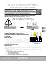
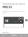
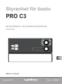
Sauna control unit PRO C
new function „Door sensor“
Supplement / change to the operating instructions:
PRO-C2 /1-015-448 , PRO-C3 /1-015-451 Version 12/21
Product manual you can nd at: https://www.sentiotec.com/downloads or
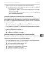
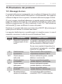
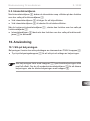
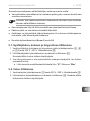
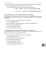
The new function ensures optimal door monitoring for remote control!
Optionale accessories: Door sensor home SAB00103 / 1-052-723
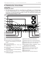
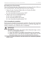
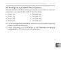
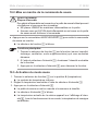
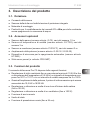
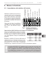
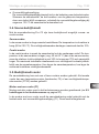
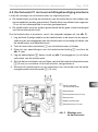
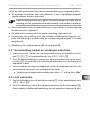
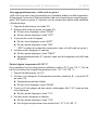
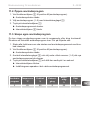
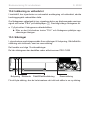
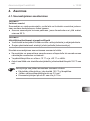
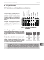
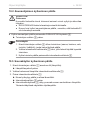
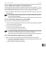
The connection position of
STB and OSG were exchanged!
Note the change in the above product manual under the following points:
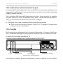
5.5. Installing bench sensor (clamp red wires at STB)
5.8. Connecting safety device or NEW connecting door sensor
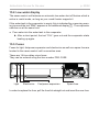
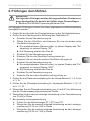
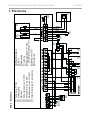
8. Starting up
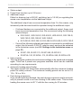
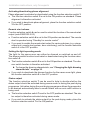
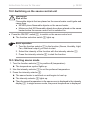
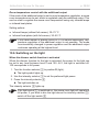
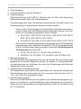
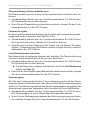
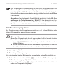
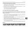
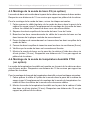
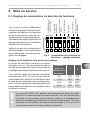
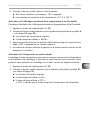
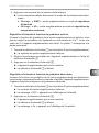
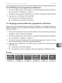
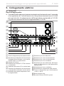
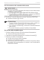
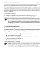
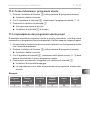
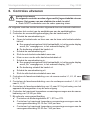
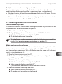
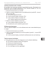
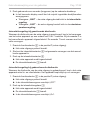
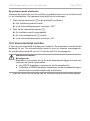
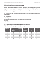
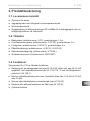
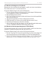
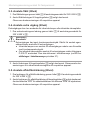
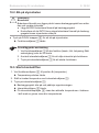
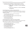
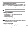
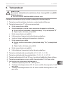
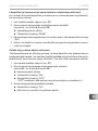
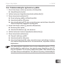
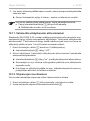
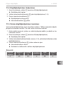
Remote start release:
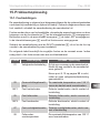
●As standard the function selection switch is in the OFF position.
The remote star is operated using „Standby for remote control“.
●If you want to enable the remote start output for various devices (e.g.
coinoperated unit, remote start system), set the function selection
switch 4 in the ON position
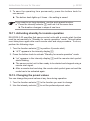
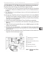
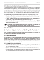
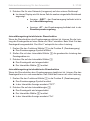
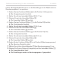
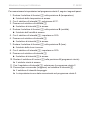
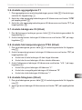
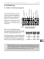
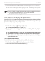
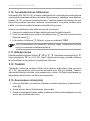
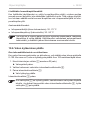
8.2. Settings in the technician menu
Activate door sensor
1. Open the technician menu (press the lower bottom knob and the ON/OFF switch at the same time)
2. Activate the door-function
If the remote start enable is switched ON, the door sensor must be activated. To do this, carry out
the following steps:
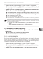
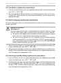
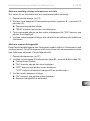
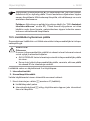
a. Turn the top knob to the remote start symbol
►The remote start symbol ash
►In the top display „SdO“ appears
►In the bottom display „SAFE“ appears (= Standard setting)
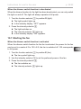
EN
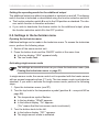
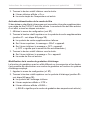
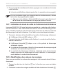
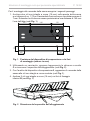
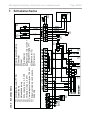
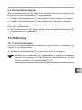
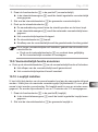
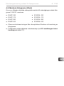
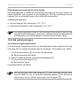
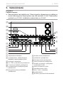
NEW
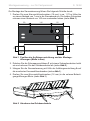
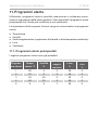
STB
Heating period
limit
Phase
alignment
Remote start
release
Status output
Light mode
Not assigned
Additional out-
put mode
OFF
OSG
STBOSG
Function selection switch
- Standard setting
DE

EN
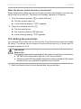
Additional sheet for instructions for use p. 2/2
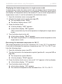
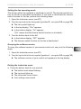
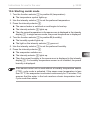
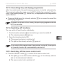
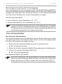
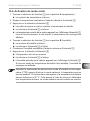
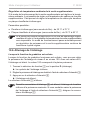
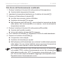
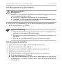
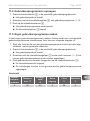
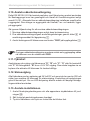
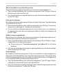
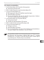
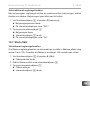
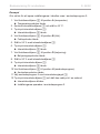
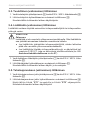
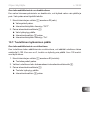
b. Turn the lower knob to the right
►In the lower display “door“ appears
3. Exiting the technician menu (Longpress on the lower knob)
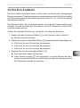
10. Operation
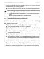
Activating „Standby for remote operation“ with door sensor
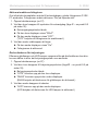
1. Turn the top knob to the remote start symbol
►In the lower display „oFF“ appears
►The remote start symbol ash.
2. Press the lower knob
►A countdown of 30 seconds is shown in the lower display. During this time, the door can be opened/
closed as often as you like. After the countdown has expired, the door must be closed!
►In the lower display „rc“ appears
►The sauna control is now ready to be started and stopped once via a remote start signal = Mode
„Standby for remote operation“
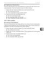
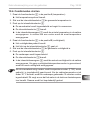
Door is opened - warning „door“ appears in the display
- at mode „Standby for remote operation“:
To continue the mode, the door must be closed and the lower button has to be press two times.
► The countdown (30 sec.) is shown again in the lower display.
- in operation or enable remot start output (for coinoperated unit or door sensor system):
The acknowledgment takes place automatically when the door is closed.
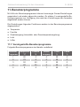
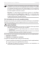
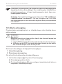
11. User programm
The settings in the user programs has been added with the function runtime (hours) . A runtime of 2 hours is
stored in all preset user programs and can be changed as described under „Creating your own user programs“.
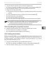
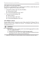
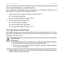
additional to PRO C3:
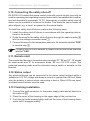
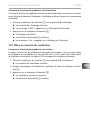
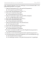
8.2. Settings in the technician menu
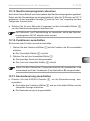
Setting the runtime of the post-drying programme
1. Open the technician menu (press the lower bottom knob and the ON/OFF switch at the same time)
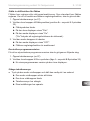
2. Turn the top knob to the humidity symbol
► The humidity symbol lights up.
► In the top display „SIn“ appears.
► In the bottom display „OFF“ appears
3. Press the lower buttom
► In the top display„dry“ appears
► In the bottom display „t60“ appears
4. Turn the lower buttom (Selection 0 - 60; 0 = post-drying progamm off , 60 = maximum runtime in minutes)
5. Exiting the technician menu (Longpress on the lower knob)
Setting option up to the set heating period limit - see starting up function selector switches 1
and 2 (standard setting 6 hours)

Version 11/22 Ident-Nr. ST-M-00007-00
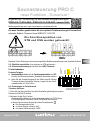
Saunasteuerung PRO C
neue Funktion „Türsensor“
Ergänzung / Änderung zu den Bedienungsanleitungen:
PRO-C2 /1-015-448 , PRO-C3 /1-015-451 Version 12/21
Bedienungsanleitung unter: https://www.sentiotec.com/downloads oder
Die neue Funktion gewährleistet die eine optimale Türüberwachung bei Fermwirken!
optionales Zubehör: Türsensor Home SAB00103 / 1-052-723
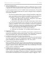
Die Anschlussposition von
STB und OSG wurden getauscht!
Beachten Sie die Änderungen in den oben angeführten Bedienungsanleitungen unter folgenden Punkten:
5.5. Ofenfühler anschließen (rote Leitungen an STB anklemmen)
5.8. Sicherheitsabschaltung anschließen bzw. NEU Türsensor
8. Inbetriebnahme
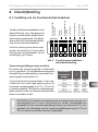
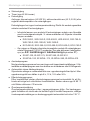
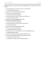
Fernstart-Freigabe:
●Standardmäßig bendet sich der Funktionswahlschalter 4 in OFF-
Position. Der Fernstart wird mittels „Standby für Fernwirken“ aktiviert.
●Wenn Sie den Fernstart-Ausgang für div. Geräte (wie z.B. Münzer,
Türsensor-System) freischalten möchten, bringen Sie den Funkti-
onswahlschalter 4 in ON-Position.
8.2. Einstellungen im Technikermenü
Türsensor aktivieren
1. Rufen Sie das Techniker-Menü auf (beim Einschalten gleichzeitig den unteren
Drehknopf und EIN/AUS drücken
2. Aktivieren Sie die Door-Funktion
Standardmäßig bendet sich der Funktionswahlschalter 4 in OFF-Position.
Zur Aktivierung des Türsensors, führen Sie folgende Schritte durch:
a. Drehen Sie den oberen Drehknopf auf das Fernstartsymbol
►Das Fernstartsymbol blinkt.
►Im oberen Display erscheint „SdO“
►Im unteren Display erscheint „SAFE“
NEU
STB
Heizzeitbe-
grenzung
Phasen-
rollierung
Fernstart-
Freigabe
Status Ausgang
Licht-
Modus
Nicht belegt
Zusatzausgang-
Modus
OFF
OSG
STBOSG
Funktionswahlschalter-
Standardeinstellung
DE

DE
Zusatzblatt zur Bedienungsanleitung S. 2/2
b. Drehen Sie den unteren Drehknopf nach rechts
►Im unteren Display erscheint “door“
3. Verlassen Sie das Technikermenü (Longpress auf unteren Drehregler)
10. Bedienung
Standby für Fernwirken (mit Türsensor) aktivieren
1. Drehen Sie den oberen Drehknopf auf das Fernstartsymbol
►Im unteren Display wird „oFF“ angezeigt
►Das Fernstartsymbol leuchtet
2. Drücken Sie den unteren Drehknopf
►Im unteren Display wird ein Countdown von 30 Sekunde angezeigt. Die Tür kann in dieser Zeit
beliebig oft geöffnet / geschlossen werden. Nach Ablauf des Countdown muss die Türe geschlos-
sen sein!
►Im unteren Display wird „rc“ angezeigt
►Die Saunasteuerung ist nun bereit um über ein Fernstartsignal einmalig gestartet und gestopt zu
werden = Modus „Standby für Fernwirken“
Tür wird geöffnet - im Display erscheint Warnung „door“
- im Modus Standby für Fernwirken:
Um den Modus fortzusetzen muss die Tür geschlossen werden und der untere Drehknopf muss zwei mal
gedrückt werden. ► Im unteren Display wird wieder der Countdown (30 Sek.) angezeigt
- im laufenden Betrieb oder freigegebenen Fernstart-Ausgang (für Münzer oder Türsensor-System):
Die Quittierung erfolgt automatisch, wenn die Tür geschlossen wird.
11. Benutzerprogramme
Die Einstellungen in den Benutzerprogrammen wurden um die Funktion Laufzeit (Stunden) erweitert. In allen
voreingestellten Benutzerprogrammen ist eine Laufzeit von 2 Stunden hinterlegt und kann, wie unter „Eigene
Benutzerprogramme erstellen“ verändert werden.
zusätzlich bei PRO C3:
8.2. Einstellungen im Technikermenü
Nachtrockenprogramm-Laufzeit einstellen
1. Rufen Sie das Techniker-Menü auf (beim Einschalten gleichzeitig den unteren Drehknopf und EIN/AUS
drücken)
2. Drehen Sie den oberen Drehknopf auf das Feuchtesymbol
► Das Feuchtesymbol blinkt.
► Im oberen Display erscheint „SIn“.
► Im unteren Display erscheint „OFF“.
3. Drücken Sie den unteren Drehknopf
► Im oberen Display erscheint „dry“
► Im unteren Display erscheint „t60
4. Drehen Sie den unteren Drehknopf (Auswahl 0 - 60; 0 = Nachtrockenprogramm ausgesschaltet,
60 = maximale Laufzeit in Minuten)
5. Verlassen Sie das Technikermenü (Longpress auf unteren Drehregler)
Einstellmöglichkeit bis maximal der eingestellten Heizzeitbegrenzung - siehe Inbetriebnahme
Funktionswahlschalter 1 und 2 (Standardeinstellung 6 Stunden)

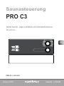
Version 12/21 ID no. 1-026-969
INSTRUCTIONS FOR INSTALLATION AND USE
English
EN
DE
FR
IT
NL
SV
FI
Sauna control unit
PRO C3
PRO-C3 / 1-015-451

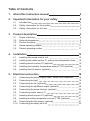
Table of Contents
1. About this instruction manual 5
2. Important information for your safety 6
2.1. Intended use 6
2.2. Safety information for the installer 7
2.3. Safety information for the user 8
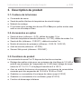
3. Product description 9
3.1. Scope of delivery 9
3.2. Optional accessories 9
3.3. Product functions 9
3.4. Sauna operating modes 11
3.5. Sensor operating modes 11
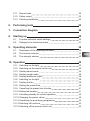
4. Installation 13
4.1. Installing the sauna control unit 13
4.2. Installing the heater sensor F1 with excess temperature fuse 15
4.3. Installing bench sensor F2 (optional) 16
4.4. Installing the humidity temperature sensor FTS2 (optional) 16
4.5. Installing the foil sensor (optional) 17
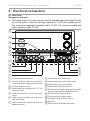
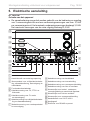
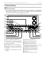
5. Electrical connection 18
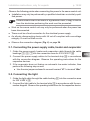
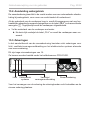
5.1. Connecting the power supply cable, heater and evaporator 19
5.2. Connecting the light 19
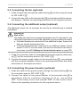
5.3. Connecting the fan (optional) 20
5.4. Connecting the additional output (optional) 20
5.5. Connecting the power booster (optional) 20
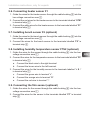
5.6. Connecting heater sensor F1 21
5.7. Installing bench sensor F2 (optional) 21
5.8. Installing humidity temperature sensor FTS2 (optional) 21
5.9. Connectingthelmsensor(optional) 21
5.10. Connectingthesafetyshut-o 22

EN
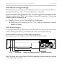
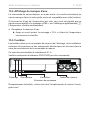
5.11. Remote start 22
5.12. Status output 22
5.13. Finishing installation 22
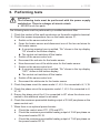
6. Performing tests 23
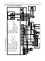
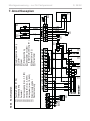
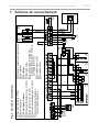
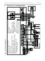
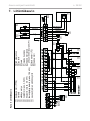
7. Connection diagram 24
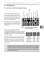
8. Starting up 25
8.1. Function selection switch settings 25
8.2. Settings in the technician menu 27
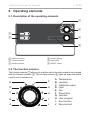
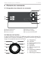
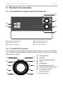
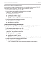
9. Operating elements 32
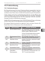
9.1. Description of the operating elements 32
9.2. The function selector 32
9.3. The intensity selector 33
10. Operation 33
10.1. Switching on the light 33
10.2. Switching on the sauna control unit 34
10.3. Starting sauna mode 34
10.4. Starting combi mode 35
10.5. Starting additional output 36
10.6. Switching on the light 38
10.7. Starting the fan 39
10.8. Setting the preset time 40
10.9. Cancelling the preset time function 41
10.10. Setting the duration 41
10.11. Activating standby for remote operation 42
10.12. Changing the preset values 42
10.13. Cancelling the post-drying programme 43
10.14.Switchingofunctions 43
10.15.Switchingothesaunacontrolunit 43

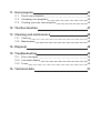
11. User program 44
11.1. Preset user programs 44
11.2. Accessing user programs 45
11.3. Creating your own user programs 45
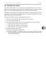
12. The Eco-function 47
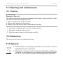
13. Cleaning and maintenance 48
13.1. Cleaning 48
13.2. Maintenance 48
14. Disposal 48
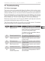
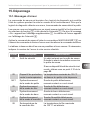
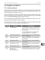
15. Troubleshooting 49
15.1. Error messages 49
15.2. Low-water display 50
15.3. Fuses 50
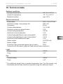
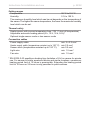
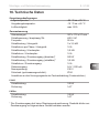
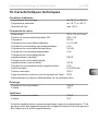
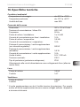
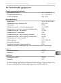
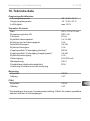
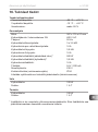
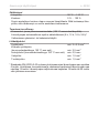
16. Technical data 51

EN
Instructions for installation and use p. 5/52
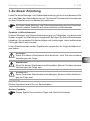
1. About this instruction manual
Read these instructions for installation and use carefully and keep them within
reach of the sauna control unit. This ensures that you can refer to information
regarding your safety and regarding operation at any time.
Symbols used for warning notices
In these instructions for installation and use, a warning notice located next to
an activity indicates that this activity poses a risk. Always observe the warning
notices. This prevents damage to property and injuries, which in the worst case
may be fatal.
The warning notices contain keywords, which have the following meanings:
DANGER!
Serious or fatal injury will occur if this warning notice is not observed.
WARNING!
Serious or fatal injury can occur if this warning notice is not observed.
CAUTION!
Minor injuries can occur if this warning notice is not observed.
ATTENTION!
This keyword is a warning that damage to property can occur.
Other symbols
This symbol indicates tips and useful information.
These installation and operating instructions can also be found in the
downloads section of our website: www.sentiotec.com/downloads.

Instructions for installation and use p. 6/52
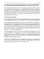
2. Important information for your safety
The sauna control unit Pro C3 has been produced in accordance
with the applicable safety regulations for technical units. However,
hazards may occur during use. Therefore adhere to the following
safetyinformationandthespecicwarningnoticesintheindividual
chapters. Also observe the safety information for the devices con-
nected.
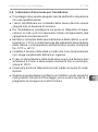
2.1. Intended use
The sauna control unit Pro C3 is used exclusively for operating and
controlling the sauna functions in accordance with the technical data.
The sauna control unit Pro C3 may only be used for operating and
controllingasaunaheaterwhichhasbeencertiedassatisfying
the combustion test described in paragraph 19.101 of EN 60335-
2-53. If the heater does not meet this requirement, an appropriate
safetyprecautionmustbetaken(forexample:safetyshut-o,see
5.10 on page 22).
The sauna control unit Pro C3 may only be used for operating and
controlling 3 heating circuits with a maximum heating capacity of
3.5 kW per heating circuit. The maximum evaporator capacity totals
3.5 kW. The maximum additional output capacity totals 3.5 kW.
Any use exceeding this scope is considered improper use. Improper
use can result in damage to the product, in severe injuries or death.

EN
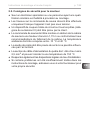
Instructions for installation and use p. 7/52
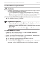
2.2. Safety information for the installer
●Installationmayonlybeperformedbyaqualiedelectricianor
similarlyqualiedperson.
●Work on the sauna control unit may only be performed when the
power has been disconnected.
● Anall-poledisconnectingdevicewithfullcut-ocompliantwith
overvoltagecategoryIIImustbettedon-site.
●The sauna control unit must be installed outside the sauna room
at a height of approx. 1.70 m or in accordance with the rec-
ommendation issued by the sauna manufacturer. The ambient
temperature must be within a range spanning -10 °C to +40 °C.
●The heater sensor must be attached in a way that it is not af-
fectedbyaowofair.
●The heater supply cable must have a minimum cross-section of
2.5 mm2 and be temperature resistant up to 150 °C.
●Also comply with the regulations applicable at the installation
location.
●For your own safety, consult your supplier in the event of prob-
lemsthatarenotexplainedinsucientdetailintheinstallation
instructions.

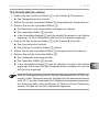
Instructions for installation and use p. 8/52
2.3. Safety information for the user
●The sauna control unit must not be used by children under
8 years old.
●The sauna control unit may only be used by children above 8 years
old, by persons with limited psychological, sensory or mental
capabilities or by persons with lack of experience/knowledge:
– When they are supervised.
– When they have been shown how to use the device safely
and are aware of the hazards that could occur.
●Children must not play with the sauna control unit.
●Children under 14 years of age may only clean the sauna control
unit if they are supervised.
● Forhealthreasons,donotusethesaunawhenundertheinu-
ence of alcohol, medication or drugs.
● Makesurethatnoammableobjectshavebeenplacedonthe
sauna heater before the sauna control unit is switched on.
● Makesurethatnoammableobjectshavebeenplacedonthe
heater before activating the preset time function or the stand-by
mode for the remote start.
●Make sure that no flammable objects have been placed on
or in front of the infrared lamp before the sauna control unit is
switched on.
● Makesurethatnoammableobjectshavebeenplacedonthe
heater before activating the infrared lamp or the stand-by mode
for the remote start.
●For your own safety, consult your supplier in the event of prob-
lemsthatarenotdescribedinsucientdetailintheoperating
instructions.

EN
Instructions for installation and use p. 9/52
3. Product description
3.1. Scope of delivery
●Sauna control unit
●Heater sensor with integrated excess temperature fuse
●Installation material
●Wire jumper for bridging terminals V1 and Wm for combi heaters without
low-watershut-o
3.2. Optional accessories
●Bench sensor (item number: O-F2), sensor wires 1.5 m
●Humidity temperature sensor (item number: O-FTS2), sensor wires 3 m
●Foil sensor (item number: P-ISX-FF), sensor wires 3 m
●Power booster (item number: O-S2-18 / O-S2-30)
● Safetyshut-o(itemnumber:HT-SWL)
●pronet web server (item number: PRO-NET)
3.3. Product functions
The sauna control unit Pro C3 features the following functions:
●Regulation of combi heaters with a heating output of up to 10.5 kW and
evaporator output of up to 3.5 kW in the temperature range spanning 30 °C
to 110 °C and a humidity range spanning 5 % to 100 %.
●A power booster allows the maximum contact rating to be increased from
10.5 kW to 18 kW or 30 kW.
●Optional dimming or activation of a room light (up to 100 W)
●Optional dimmer function or activation of a fan (up to 100 W)
●Remote start function

Instructions for installation and use p. 10/52
●Status output
●Preset time function (up to 24 hours)
●Additional output
Either for dimming (up to 500 W), switching (up to 3.5 kW) or regulating the
sauna room temperature via the additional output.
The additional output has no excess temperature fuse. For this reason, only
intrinsically safe devices should be operated using the additional output.
– If infrared heaters are connected to the additional output, these must
have an excess temperature fuse. We recommend using the following
infrared lamps:
●DIR-350-R, WIR-350-R, DIR-500-R, WIR-500-R, DIR-750-R,
WIR-750-R, DIR-1300-R, WIR-1300-R
●ECO-350-R, ECO-350-G, ECO-500-R, ECO-500-G, ECO-750-R
– If one of the following infrared heat plates is connected to an additional
output, the foil sensor P-ISX-FF must be used, and must be activated
in the technician menu (see 8.2. Settings in the technician menu on
page 27):
●IR-WP-100, IR-WP-175, IR-WP-390, IR-WP-510
●IR-WPHL-100, IR-WPHL-175, IR-WPHL-390, IR-WPHL-510
●User program
The user program enables favourite sauna settings to be saved and accessed
again.Thereare5presetuserprogramsavailablewhichcanbemodied
according to user requirements.
●Automatic heating period limiter
The sauna control unit shuts down automatically after the maximum heating
period for safety reasons. The maximum heating period can be set to 6 h,
12 h, 18 h or 24 h.
●Post-drying programme
Oncecombi-modehasnished,thepost-dryingprogrammestartsautomati-
cally to prevent mould or rot from forming in the sauna room. This involves
heating the sauna room to 80 °C with the fan running for 30 minutes.

EN
Instructions for installation and use p. 11/52
●Excess temperature fuse
The excess temperature fuse is installed in the housing for the heater sen-
sor. Should the sauna heater continue heating after reaching the preferred
temperature due to a defect, the excess temperature fuse switches the sauna
heateroatatemperatureofapprox.139°C.
3.4. Sauna operating modes
The sauna control unit Pro C3 provides two operating modes, sauna mode and
combi mode.
Sauna mode
Dry heat is provided in sauna mode. The temperature in the room is high (80 to
100 °C) The humidity level of maximum 10 % is low.
Combi mode
The evaporator operates along with the sauna heater in combi mode. The
temperature in the sauna room is lower (approx. 40 to 65 °C) than in sauna
mode, with the relative humidity being considerably higher, spanning 35 % to
approximately 70 %. The maximum humidity level which can be set depends on
the temperature of the sauna. The higher the sauna temperature, the lower the
maximum humidity level which can be set.
3.5. Sensor operating modes
The sauna control unit can be operated with one or two sensors. A temperature
sensor (bench sensor, F2) or a humidity sensor (FTS2) can be used as the
second sensor.
Single-sensor mode (F1)
Single-sensor mode must be activated in the technician menu (see 8.2. Settings
in the technician menu on page 27).
In single-sensor mode, the sauna control unit is operated with the heater sensor
with excess temperature fuse (F1) only. This is included in the scope of delivery.

Instructions for installation and use p. 12/52
In single-sensor mode, the sauna control unit only displays the set temperature
as standard. The actual temperature is not displayed. Should the sauna control
unit display the temperature above the heater (F1) as an actual temperature in
single-sensormode,itmustbeactivatedwhenstartingupforthersttime(see
8.2. Settings in the technician menu on page 27)
The maximum humidity level which can be set in single-sensor mode is based
on the temperature above the heater and the humidity is timed. Only the set
value for the humidity level (in % of relative humidity) is displayed by the sauna
control unit. The actual humidity level in the sauna room when humidity is timed
depends on the size of the room and the evaporator capacity, and may deviate
from the set value.
Two-sensor mode with bench sensor (F2)
In two-sensor mode with bench sensor, a second temperature sensor (bench
sensor) is installed above the rear sauna bench. The sauna control unit displays
the temperature measured by the bench sensor as the actual temperature.
In two-sensor mode with bench sensor, the humidity is timed. Only the set
value for the humidity level (in % of relative humidity) is displayed by the sauna
control unit. The actual humidity level in the sauna room when humidity is timed
depends on the size of the room and the evaporator capacity, and may deviate
from the set value.
Two-sensor mode with humidity temperature sensor (FTS2)
When a humidity temperature sensor is used in two-sensor mode, the sauna
control unit displays the temperature which is measured by the humidity tem-
perature sensor as the actual temperature.
In two-sensor mode with humidity temperature sensor, the evaporator is regu-
lated in accordance with the humidity level measured in the sauna room. The
actual value for the humidity level (in % of relative humidity) is displayed by the
sauna control unit.

EN
Installation instructions, only for experts p. 13/52
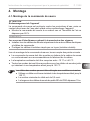
4. Installation
4.1. Installing the sauna control unit
Observe the following points when installing the sauna control unit:
●The sauna control unit must be installed outside the sauna room or in accord-
ance with the recommendation issued by the sauna manufacturer.
●The ambient temperature must be within a range spanning -10 °C to +40 °C.
●The sensors may only be connected using the sensor wires provided with the
unit, which are heat-resistant up to 150 °C.
ATTENTION!
Damage to the unit
The sauna control unit is protected against jets of water, however direct contact
with water could still damage the unit.
●Install the sauna control unit in a dry place at which a maximum humidity of
95 % is not exceeded.
The sensor wires may be extended under the following conditions:
●When a silicon wire resistant to temperatures up to 150 °C is used.
●The minimum cross-section of the wire is 0.5 mm2.
●The length of the heater sensor wires may NOT exceed 10 m.
ATTENTION!
Sources of interference can have a negative eect on signal transmission
●Lay all sensor wires separately from other mains wires and control wires.
●Protect wires with only one layer of insulation by using a pipe (double insulation).

Installation instructions, only for experts p. 14/52
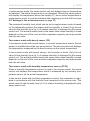
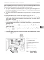
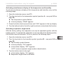
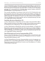
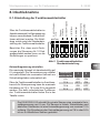
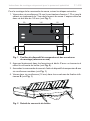
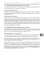
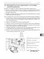
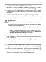
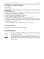
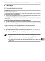
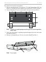
Fig. 1 Position of the attachment device and the installation holes
(dimensions in mm)
C
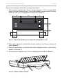
To install the sauna control unit, perform the following steps:
1. Screw two Phillips-head screws (16 mm) into the wall of the sauna at a height
of approx. 1.70 m to a distance of up to 7 mm. The two screws must be
placed at a distance of 145 mm from each other (see Fig. 1).
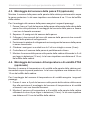
2. Press the clip locks C in lightly using a screwdriver and remove the cover
from the housing (see Fig. 2).
3. Fasten the sauna control unit onto the Phillips-head screws using the at-
tachment device A as an aid (see Fig. 1).
4. Screw two Phillips-head screws (16 mm) into the lower fastening holes B
(see Fig. 1).
82
80
34
175
145
34
43
40
A
B
Fig. 2 Removing the cover from the housing

EN
Installation instructions, only for experts p. 15/52
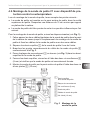
4.2. Installing the heater sensor F1 with excess temperature fuse
Observe the following points when installing the heater sensor:
●The heater sensor must be installed on the rear of the heater, above the mid-
dle of the sauna heater. An interval of approx. 15 cm to the roof of the sauna
room must be maintained.
● Theheatersensormustbeattachedinawaythatitisnotaectedbyaow
of air.
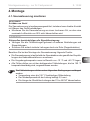
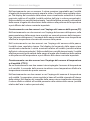
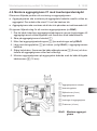
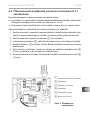
To install the heater sensor, perform the following steps (see Fig. 3):
1. Lay the two 2-pin heater sensor wires in the wall of the sauna room, leading
themtotheheatersensorinstallationlocationandaxtheheatersensor
wires using wire clips.
2. Pull the two half-shells 1 of the heater sensor apart.
3. Connect the four connectors for the heater sensor wire 5 in accordance
with the Fig. 3.
4. Place the connection panel 2 crossways (as shown in Fig. 3) in the heater
sensor half-shells.
5. Place the two half-shells together, screw them together using the two Phillips-
head screws 3 (9 mm) and check whether the heater sensor has been
securely closed.
6. Install the heater sensor on the rear of the heater using the two wood screws
enclosed 6 (16 mm).
1 Heater sensor half-shells
2 Connection panel
3 Phillips-head screws (9 mm)
4 Heater sensor
5 Heater sensor wires
6 Wood screws (16 mm)
Fig. 3 Installing the
heater sensor
Red
White
White
Red

Installation instructions, only for experts p. 16/52
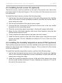
4.3. Installing bench sensor F2 (optional)
The bench sensor must be installed on the wall of the sauna room, above the
rear bench seat. An interval of approx. 15 cm to the roof of the sauna room must
be maintained.
To install the bench sensor, perform the following steps:
1. Lay the two 2-pin bench sensor wires in the wall of the sauna room, leading
themtothebenchsensorinstallationlocationandaxthebenchsensor
wires using wire clips.
2. Pull the two half-shells of the bench sensor apart.
3. Connect the two connectors for the bench sensor wire to the two middle
terminals on the connection panel.
4. Place the connection panel crossways in the bench sensor half-shells.
5. Place the two half-shells together and screw them together using the two
Phillips-head screws (9 mm).
6. Check whether the bench sensor has been securely closed.
7. Install the bench sensor on the wall of the sauna room using the two wood
screws enclosed (16 mm). Maintain an interval of 15 cm to the roof of the
sauna room.
4.4. Installing the humidity temperature sensor FTS2 (optional)
The humidity temperature sensor must be installed on the wall of the sauna room
above the rear bench seat. A distance of approx. 15 cm to the roof of the sauna
must be maintained.
To install the humidity temperature sensor, perform the following steps:
1. Lay the two 5-pin bench sensor wires in the wall of the sauna room, leading
themtothehumiditytemperaturesensorinstallationlocationandaxthe
sensor wires using wire clips.
2. Install the humidity temperature sensor to the wall of the sauna room using
the two wood screws enclosed (16 mm). Maintain an interval of 15 cm to
the roof of the sauna room.
Sidan laddas...
Sidan laddas...
Sidan laddas...
Sidan laddas...
Sidan laddas...
Sidan laddas...
Sidan laddas...
Sidan laddas...
Sidan laddas...
Sidan laddas...
Sidan laddas...
Sidan laddas...
Sidan laddas...
Sidan laddas...
Sidan laddas...
Sidan laddas...
Sidan laddas...
Sidan laddas...
Sidan laddas...
Sidan laddas...
Sidan laddas...
Sidan laddas...
Sidan laddas...
Sidan laddas...
Sidan laddas...
Sidan laddas...
Sidan laddas...
Sidan laddas...
Sidan laddas...
Sidan laddas...
Sidan laddas...
Sidan laddas...
Sidan laddas...
Sidan laddas...
Sidan laddas...
Sidan laddas...
Sidan laddas...
Sidan laddas...
Sidan laddas...
Sidan laddas...
Sidan laddas...
Sidan laddas...
Sidan laddas...
Sidan laddas...
Sidan laddas...
Sidan laddas...
Sidan laddas...
Sidan laddas...
Sidan laddas...
Sidan laddas...
Sidan laddas...
Sidan laddas...
Sidan laddas...
Sidan laddas...
Sidan laddas...
Sidan laddas...
Sidan laddas...
Sidan laddas...
Sidan laddas...
Sidan laddas...
Sidan laddas...
Sidan laddas...
Sidan laddas...
Sidan laddas...
Sidan laddas...
Sidan laddas...
Sidan laddas...
Sidan laddas...
Sidan laddas...
Sidan laddas...
Sidan laddas...
Sidan laddas...
Sidan laddas...
Sidan laddas...
Sidan laddas...
Sidan laddas...
Sidan laddas...
Sidan laddas...
Sidan laddas...
Sidan laddas...
Sidan laddas...
Sidan laddas...
Sidan laddas...
Sidan laddas...
Sidan laddas...
Sidan laddas...
Sidan laddas...
Sidan laddas...
Sidan laddas...
Sidan laddas...
Sidan laddas...
Sidan laddas...
Sidan laddas...
Sidan laddas...
Sidan laddas...
Sidan laddas...
Sidan laddas...
Sidan laddas...
Sidan laddas...
Sidan laddas...
Sidan laddas...
Sidan laddas...
Sidan laddas...
Sidan laddas...
Sidan laddas...
Sidan laddas...
Sidan laddas...
Sidan laddas...
Sidan laddas...
Sidan laddas...
Sidan laddas...
Sidan laddas...
Sidan laddas...
Sidan laddas...
Sidan laddas...
Sidan laddas...
Sidan laddas...
Sidan laddas...
Sidan laddas...
Sidan laddas...
Sidan laddas...
Sidan laddas...
Sidan laddas...
Sidan laddas...
Sidan laddas...
Sidan laddas...
Sidan laddas...
Sidan laddas...
Sidan laddas...
Sidan laddas...
Sidan laddas...
Sidan laddas...
Sidan laddas...
Sidan laddas...
Sidan laddas...
Sidan laddas...
Sidan laddas...
Sidan laddas...
Sidan laddas...
Sidan laddas...
Sidan laddas...
Sidan laddas...
Sidan laddas...
Sidan laddas...
Sidan laddas...
Sidan laddas...
Sidan laddas...
Sidan laddas...
Sidan laddas...
Sidan laddas...
Sidan laddas...
Sidan laddas...
Sidan laddas...
Sidan laddas...
Sidan laddas...
Sidan laddas...
Sidan laddas...
Sidan laddas...
Sidan laddas...
Sidan laddas...
Sidan laddas...
Sidan laddas...
Sidan laddas...
Sidan laddas...
Sidan laddas...
Sidan laddas...
Sidan laddas...
Sidan laddas...
Sidan laddas...
Sidan laddas...
Sidan laddas...
Sidan laddas...
Sidan laddas...
Sidan laddas...
Sidan laddas...
Sidan laddas...
Sidan laddas...
Sidan laddas...
Sidan laddas...
Sidan laddas...
Sidan laddas...
Sidan laddas...
Sidan laddas...
Sidan laddas...
Sidan laddas...
Sidan laddas...
Sidan laddas...
Sidan laddas...
Sidan laddas...
Sidan laddas...
Sidan laddas...
Sidan laddas...
Sidan laddas...
Sidan laddas...
Sidan laddas...
Sidan laddas...
Sidan laddas...
Sidan laddas...
Sidan laddas...
Sidan laddas...
Sidan laddas...
Sidan laddas...
Sidan laddas...
Sidan laddas...
Sidan laddas...
Sidan laddas...
Sidan laddas...
Sidan laddas...
Sidan laddas...
Sidan laddas...
Sidan laddas...
Sidan laddas...
Sidan laddas...
Sidan laddas...
Sidan laddas...
Sidan laddas...
Sidan laddas...
Sidan laddas...
Sidan laddas...
Sidan laddas...
Sidan laddas...
Sidan laddas...
Sidan laddas...
Sidan laddas...
Sidan laddas...
Sidan laddas...
Sidan laddas...
Sidan laddas...
Sidan laddas...
Sidan laddas...
Sidan laddas...
Sidan laddas...
Sidan laddas...
Sidan laddas...
Sidan laddas...
Sidan laddas...
Sidan laddas...
Sidan laddas...
Sidan laddas...
Sidan laddas...
Sidan laddas...
Sidan laddas...
Sidan laddas...
Sidan laddas...
Sidan laddas...
Sidan laddas...
Sidan laddas...
Sidan laddas...
Sidan laddas...
Sidan laddas...
Sidan laddas...
Sidan laddas...
Sidan laddas...
Sidan laddas...
Sidan laddas...
Sidan laddas...
Sidan laddas...
Sidan laddas...
Sidan laddas...
Sidan laddas...
Sidan laddas...
Sidan laddas...
Sidan laddas...
Sidan laddas...
Sidan laddas...
Sidan laddas...
Sidan laddas...
Sidan laddas...
Sidan laddas...
Sidan laddas...
Sidan laddas...
Sidan laddas...
Sidan laddas...
Sidan laddas...
Sidan laddas...
Sidan laddas...
Sidan laddas...
Sidan laddas...
Sidan laddas...
Sidan laddas...
Sidan laddas...
Sidan laddas...
Sidan laddas...
Sidan laddas...
Sidan laddas...
Sidan laddas...
Sidan laddas...
Sidan laddas...
Sidan laddas...
Sidan laddas...
Sidan laddas...
Sidan laddas...
Sidan laddas...
Sidan laddas...
Sidan laddas...
Sidan laddas...
Sidan laddas...
Sidan laddas...
Sidan laddas...
Sidan laddas...
Sidan laddas...
Sidan laddas...
Sidan laddas...
Sidan laddas...
Sidan laddas...
Sidan laddas...
Sidan laddas...
Sidan laddas...
Sidan laddas...
Sidan laddas...
Sidan laddas...
Sidan laddas...
Sidan laddas...
Sidan laddas...
Sidan laddas...
Sidan laddas...
Sidan laddas...
Sidan laddas...
Sidan laddas...
Sidan laddas...
Sidan laddas...
Sidan laddas...
Sidan laddas...
Sidan laddas...
Sidan laddas...
Sidan laddas...
Sidan laddas...
Sidan laddas...
Sidan laddas...
Sidan laddas...
Sidan laddas...
Sidan laddas...
Sidan laddas...
Sidan laddas...
Sidan laddas...
Sidan laddas...
Sidan laddas...
Sidan laddas...
Sidan laddas...
Sidan laddas...
Sidan laddas...
Sidan laddas...
Sidan laddas...
Sidan laddas...
Sidan laddas...
Sidan laddas...
Sidan laddas...
Sidan laddas...
Sidan laddas...
Sidan laddas...
Sidan laddas...
Sidan laddas...
-
 1
1
-
 2
2
-
 3
3
-
 4
4
-
 5
5
-
 6
6
-
 7
7
-
 8
8
-
 9
9
-
 10
10
-
 11
11
-
 12
12
-
 13
13
-
 14
14
-
 15
15
-
 16
16
-
 17
17
-
 18
18
-
 19
19
-
 20
20
-
 21
21
-
 22
22
-
 23
23
-
 24
24
-
 25
25
-
 26
26
-
 27
27
-
 28
28
-
 29
29
-
 30
30
-
 31
31
-
 32
32
-
 33
33
-
 34
34
-
 35
35
-
 36
36
-
 37
37
-
 38
38
-
 39
39
-
 40
40
-
 41
41
-
 42
42
-
 43
43
-
 44
44
-
 45
45
-
 46
46
-
 47
47
-
 48
48
-
 49
49
-
 50
50
-
 51
51
-
 52
52
-
 53
53
-
 54
54
-
 55
55
-
 56
56
-
 57
57
-
 58
58
-
 59
59
-
 60
60
-
 61
61
-
 62
62
-
 63
63
-
 64
64
-
 65
65
-
 66
66
-
 67
67
-
 68
68
-
 69
69
-
 70
70
-
 71
71
-
 72
72
-
 73
73
-
 74
74
-
 75
75
-
 76
76
-
 77
77
-
 78
78
-
 79
79
-
 80
80
-
 81
81
-
 82
82
-
 83
83
-
 84
84
-
 85
85
-
 86
86
-
 87
87
-
 88
88
-
 89
89
-
 90
90
-
 91
91
-
 92
92
-
 93
93
-
 94
94
-
 95
95
-
 96
96
-
 97
97
-
 98
98
-
 99
99
-
 100
100
-
 101
101
-
 102
102
-
 103
103
-
 104
104
-
 105
105
-
 106
106
-
 107
107
-
 108
108
-
 109
109
-
 110
110
-
 111
111
-
 112
112
-
 113
113
-
 114
114
-
 115
115
-
 116
116
-
 117
117
-
 118
118
-
 119
119
-
 120
120
-
 121
121
-
 122
122
-
 123
123
-
 124
124
-
 125
125
-
 126
126
-
 127
127
-
 128
128
-
 129
129
-
 130
130
-
 131
131
-
 132
132
-
 133
133
-
 134
134
-
 135
135
-
 136
136
-
 137
137
-
 138
138
-
 139
139
-
 140
140
-
 141
141
-
 142
142
-
 143
143
-
 144
144
-
 145
145
-
 146
146
-
 147
147
-
 148
148
-
 149
149
-
 150
150
-
 151
151
-
 152
152
-
 153
153
-
 154
154
-
 155
155
-
 156
156
-
 157
157
-
 158
158
-
 159
159
-
 160
160
-
 161
161
-
 162
162
-
 163
163
-
 164
164
-
 165
165
-
 166
166
-
 167
167
-
 168
168
-
 169
169
-
 170
170
-
 171
171
-
 172
172
-
 173
173
-
 174
174
-
 175
175
-
 176
176
-
 177
177
-
 178
178
-
 179
179
-
 180
180
-
 181
181
-
 182
182
-
 183
183
-
 184
184
-
 185
185
-
 186
186
-
 187
187
-
 188
188
-
 189
189
-
 190
190
-
 191
191
-
 192
192
-
 193
193
-
 194
194
-
 195
195
-
 196
196
-
 197
197
-
 198
198
-
 199
199
-
 200
200
-
 201
201
-
 202
202
-
 203
203
-
 204
204
-
 205
205
-
 206
206
-
 207
207
-
 208
208
-
 209
209
-
 210
210
-
 211
211
-
 212
212
-
 213
213
-
 214
214
-
 215
215
-
 216
216
-
 217
217
-
 218
218
-
 219
219
-
 220
220
-
 221
221
-
 222
222
-
 223
223
-
 224
224
-
 225
225
-
 226
226
-
 227
227
-
 228
228
-
 229
229
-
 230
230
-
 231
231
-
 232
232
-
 233
233
-
 234
234
-
 235
235
-
 236
236
-
 237
237
-
 238
238
-
 239
239
-
 240
240
-
 241
241
-
 242
242
-
 243
243
-
 244
244
-
 245
245
-
 246
246
-
 247
247
-
 248
248
-
 249
249
-
 250
250
-
 251
251
-
 252
252
-
 253
253
-
 254
254
-
 255
255
-
 256
256
-
 257
257
-
 258
258
-
 259
259
-
 260
260
-
 261
261
-
 262
262
-
 263
263
-
 264
264
-
 265
265
-
 266
266
-
 267
267
-
 268
268
-
 269
269
-
 270
270
-
 271
271
-
 272
272
-
 273
273
-
 274
274
-
 275
275
-
 276
276
-
 277
277
-
 278
278
-
 279
279
-
 280
280
-
 281
281
-
 282
282
-
 283
283
-
 284
284
-
 285
285
-
 286
286
-
 287
287
-
 288
288
-
 289
289
-
 290
290
-
 291
291
-
 292
292
-
 293
293
-
 294
294
-
 295
295
-
 296
296
-
 297
297
-
 298
298
-
 299
299
-
 300
300
-
 301
301
-
 302
302
-
 303
303
-
 304
304
-
 305
305
-
 306
306
-
 307
307
-
 308
308
-
 309
309
-
 310
310
-
 311
311
-
 312
312
-
 313
313
-
 314
314
-
 315
315
-
 316
316
-
 317
317
-
 318
318
-
 319
319
-
 320
320
-
 321
321
-
 322
322
-
 323
323
-
 324
324
-
 325
325
-
 326
326
-
 327
327
-
 328
328
-
 329
329
-
 330
330
-
 331
331
-
 332
332
-
 333
333
-
 334
334
-
 335
335
-
 336
336
-
 337
337
-
 338
338
-
 339
339
-
 340
340
-
 341
341
-
 342
342
-
 343
343
-
 344
344
-
 345
345
-
 346
346
-
 347
347
-
 348
348
-
 349
349
-
 350
350
-
 351
351
-
 352
352
-
 353
353
-
 354
354
-
 355
355
-
 356
356
-
 357
357
-
 358
358
-
 359
359
-
 360
360
-
 361
361
-
 362
362
-
 363
363
-
 364
364
-
 365
365
-
 366
366
-
 367
367
-
 368
368
-
 369
369
-
 370
370
-
 371
371
-
 372
372


på andra språk
- italiano: Sentiotec Pro C3 Manuale utente
- eesti: Sentiotec Pro C3 Kasutusjuhend
- français: Sentiotec Pro C3 Manuel utilisateur
- English: Sentiotec Pro C3 User manual
- Nederlands: Sentiotec Pro C3 Handleiding
Relaterade papper
-
Sentiotec Pro B3 Användarmanual
-
-
-
-
-
-
Sentiotec Concept R combi Användarmanual
-
-
HARVIA SENTIO pronet Användarmanual
-
Andra dokument
-
HUUM GSM/ Wi-Fi/ Local Heater Control Console Användarmanual
-
-
-
-
-
-
Tylö CC200 Operating Instructions Manual
-
HARVIA SW90E Instructions For Installation And Use Manual
-
Mennekes Wallbox Amtron Compact Användarmanual