
Version 01/23 Ident-Nr. ST-M-00007-01
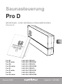
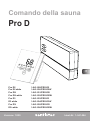
Sauna control unit PRO D
new function „Door sensor“
Supplement / change to the operating instructions:
PRO-D /1-041-284 Version 12/20
Product manual you can nd at: https://www.sentiotec.com/downloads or
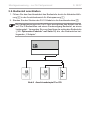
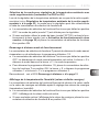
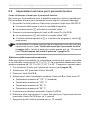
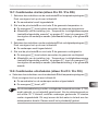
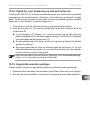
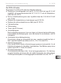
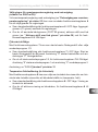
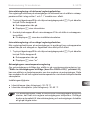
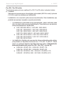
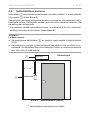
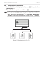
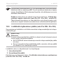
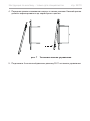
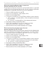
The new function ensures optimal door monitoring for remote control!
Optionale accessories: Door sensor home SAB00103 / 1-052-723
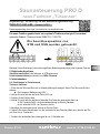
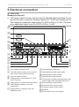
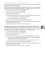
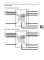
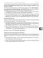
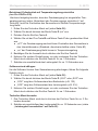
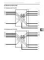
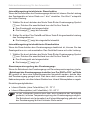
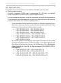
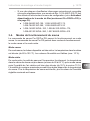
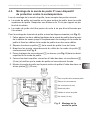
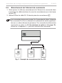
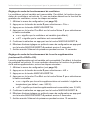
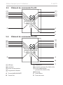
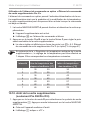
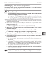
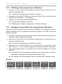
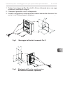
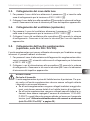
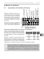
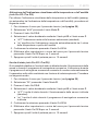
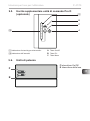
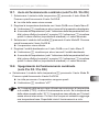
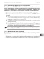
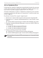
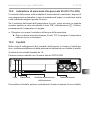
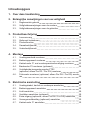
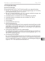
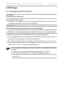
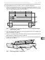
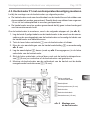
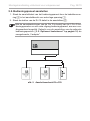
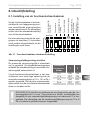
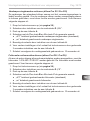
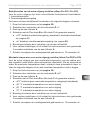
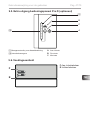
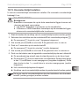
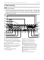
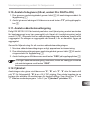
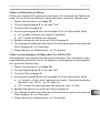
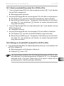
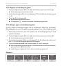
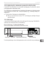
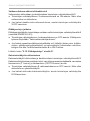
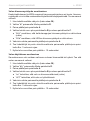
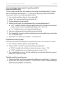
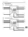
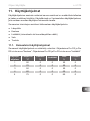
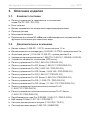
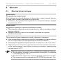
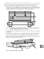
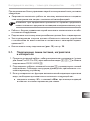
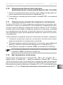
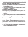
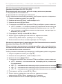
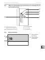
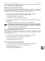
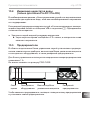
The connection position of
STB and OSG were exchanged!
Note the change in the above product manual under the following points:
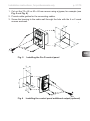
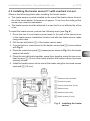
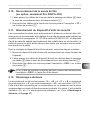
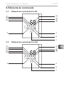
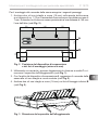
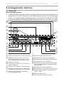
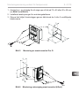
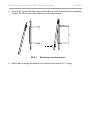
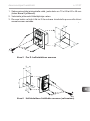
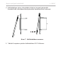
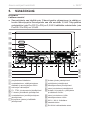
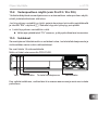
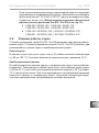
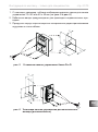
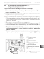
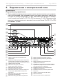
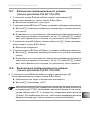
5. Electrical connection
Installing heater sensor (clamp red wires at STB)
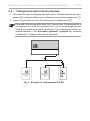
Connecting safety device or NEW connecting door sensor at OSG clamp
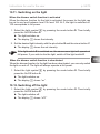
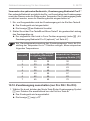
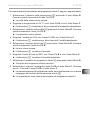
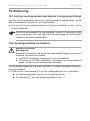
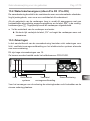
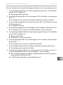
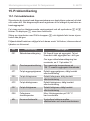
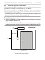
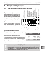
8. Starting up
8.2. Settings in the technician menu
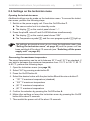
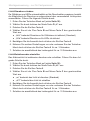
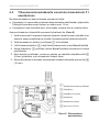
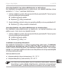
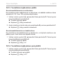
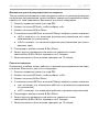
Activate door sensor
1. Open the technician menu (Press the plus, minus and On/Off buttons simultaneously)
►The display shows “SEt”
2. Select “SdO” by pressing the mode button.
3. Press the On/Off button
4. Select the desired setting by using the plus button and the minus button.
● „SAF“ means SAFE - the safety device is activated (=standard)
● „dor“ means DOOR - the door sensor is activated
5. Conrm the selection by pressing the On/Off button.
6. Make other settings or leave the technician menu by pressing the On/Off button for about 3 seconds.
7. Then switch the power unit off for about 10 seconds.
EN
NEW
STB OSG
STBOSG
DE

EN
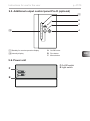
Additional sheet for instructions for use p. 2/2
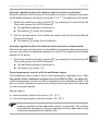
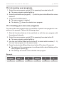
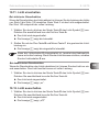
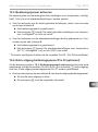
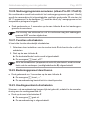
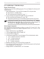
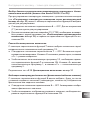
Additional new settings
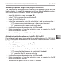
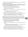
Maximum preset time in hours
1. Open the technician menu
2. Select “tL” by pressing the mode button.
3. Press the On/Off button
4. Select the desired setting using the plus button and the minus button
● adjustable values: 6h (=standard) / 12h / 18h / 24h
5. Conrm the selection by pressing the On/Off button.
6. Make other settings or leave the technician menu by pressing the On/Off button for about 3 seconds.
7. Then switch the power unit off for about 10 seconds.
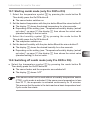
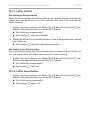
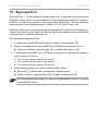
Running time for post-drying program in minutes
1. Open the technician menu
2. Select “drY” by pressing the mode button.
3. Press the On/Off button
4. Select the desired setting using the plus button and the minus button
● adjustable values: oFF up to 60 min (30 = standard)
5. Conrm the selection by pressing the On/Off button.
6. Make other settings or leave the technician menu by pressing the On/Off button for about 3 seconds.
7. Then switch the power unit off for about 10 seconds.
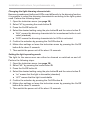
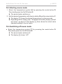
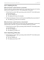
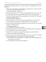
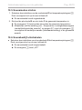
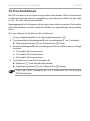
10. Operation
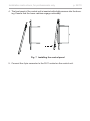
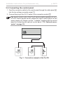
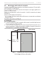
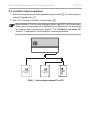
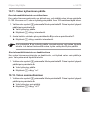
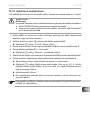
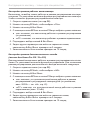
Activating „Standby for remote operation“ with door sensor
Make sure that the sauna control unit is in standby mode
1. Press the On/Off button and the mode button simultaneously for about 3 seconds.
►A countdown of 30 seconds is shown in the display. During this time, the door can be opened/closed
as often as you like. After the countdown has expired, the door must be closed!
►In the display „rc“ appears
►The sauna control is now ready to be started and stopped once via a remote start signal = Mode
„Standby for remote operation“
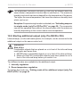
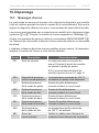
Door is opened - warning „dor“ appears in the display
- at mode „Standby for remote operation“:
To continue the mode, the door must be closed and the On/Off button has to be press for about 3 seconds.
► The countdown (30 sec.) is shown again in the display.
- in at mode „Standby“ (---):
The acknowledgment takes place automatically when the door is closed.

Version 01/23 Ident-Nr. ST-M-00008-00
Saunasteuerung PRO D
neue Funktion „Türsensor“
Ergänzung / Änderung zu der Bedienungsanleitung:
PRO-D /1-041-284 Version 12/20
Bedienungsanleitung unter: https://www.sentiotec.com/downloads oder
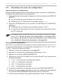
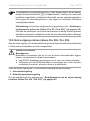
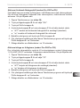
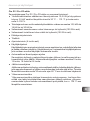
Die neue Funktion gewährleistet eine optimale Türüberwachung bei Fernwirken!
optionales Zubehör: Türsensor Home SAB00103 / 1-052-723
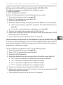
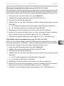
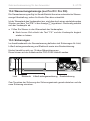
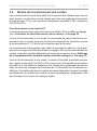
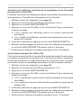
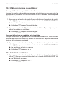
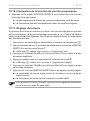
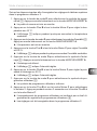
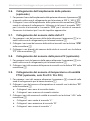
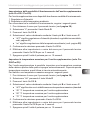
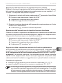
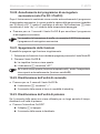
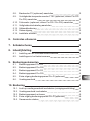
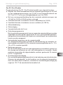
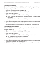
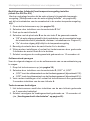
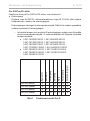
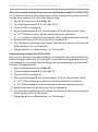
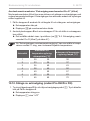
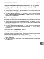
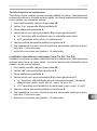
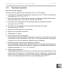
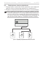
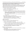
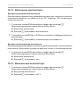
Die Anschlussposition von
STB und OSG wurden getauscht!
Beachten Sie die Änderungen in den oben angeführten Bedienungsanleitungen unter folgenden Punkten:
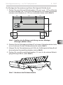
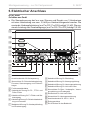
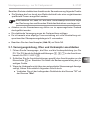
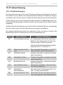
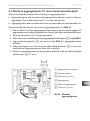
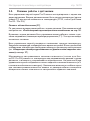
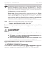
5. Elektrischer Anschluss
Ofenfühler anschließen (rote Leitungen an STB anklemmen)
Sicherheitsabschaltung anschließen bzw. NEU Türsensor
8. Inbetriebnahme
8.2. Einstellungen im Technikermenü
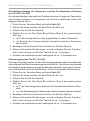
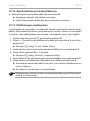
Türsensor aktivieren
1. Rufen Sie das Techniker-Menü auf (im Standby-Modus gleichzeitig die Tasten Plus, Minus und Ein/Aus
drücken)
►Die Anzeige am Bedienteil zeigt „SEt“
2. Wählen Sie durch drücken der Mode-Taste „SdO“ aus.
3. Drücken Sie die Ein/Aus-Taste
4. Wählen Sie durch drücken der Minus-Taste oder Plus-Taste den gewünschten Wert aus.
● „SAF“ bedeutet SAFE - die Sicherheitabschaltung ist aktiviert (Standard)
● „dor“ bedeutet DOOR - der Türsensor ist aktiv
5. Bestätigen Sie die Auswahl durch drücken der Ein/Aus-Taste.
6. Nehmen Sie weitere Einstellungen vor oder verlassen Sie das Techniker-Menü durch drücken der Ein/
Aus-Taste für ca. 3 Sekunden.
7. Schalten Sie anschließend das Leistungsteil für ca. 10 Sekunden aus.
NEU
STB OSG
STBOSG
DE

DE
Zusatzblatt zur Bedienungsanleitung S. 2/2
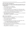
Zusätzliche neue Einstellungen
Maximale Vorwahlzeit in Stunden
1. Rufen Sie das Techniker-Menü auf
2. Wählen Sie durch drücken der Mode-Taste „tL“ aus.
3. Drücken Sie die Ein/Aus-Taste
4. Wählen Sie durch drücken der Minus-Taste oder Plus-Taste den gewünschten Wert aus.
● Einstellbare Werte 6h (=standard) / 12h / 18h / 24h
5. Bestätigen Sie die Auswahl durch drücken der Ein/Aus-Taste.
6. Nehmen Sie weitere Einstellungen vor oder verlassen Sie das Techniker-Menü durch drücken der Ein/
Aus-Taste für ca. 3 Sekunden.
7. Schalten sie anschließend das Leistungsteil für ca. 10 Sekunden aus.
Laufzeit Nachtrockenprogramm in Minuten
1. Rufen Sie das Techniker-Menü auf
2. Wählen Sie durch drücken der Mode-Taste „drY“ aus.
3. Drücken Sie die Ein/Aus-Taste
4. Wählen Sie durch drücken der Minus-Taste oder Plus-Taste den gewünschten Wert aus.
● Einstellbare Werte: oFF bis 60 min (30 =standard)
5. Bestätigen Sie die Auswahl durch drücken der Ein/Aus-Taste.
6. Nehmen Sie weitere Einstellungen vor oder verlassen Sie das Techniker-Menü durch drücken der Ein/
Aus-Taste für ca. 3 Sekunden.
7. Schalten sie anschließend das Leistungsteil für ca. 10 Sekunden aus.
10. Bedienung
Standby für Fernwirken (mit Türsensor) aktivieren
Stellen Sie sicher, dass sich die Saunasteuerung im Standby-Modus bendet.
1. Drücken Sie für ca. 3 Sekunden gleichzeitig die Ein/Aus-Taste und die Mode-Taste
►In der Anzeige wird ein Countdown von 30 Sekunde angezeigt. Die Tür kann in dieser Zeit beliebig
oft geöffnet / geschlossen werden. Nach Ablauf des Countdown muss die Türe geschlossen sein!
►In der Anzeige wird „rc“ angezeigt
►Die Saunasteuerung ist nun bereit, um über ein Fernstartsignal einmalig gestartet und gestoppt
zu werden = Modus „Standby für Fernwirken“
Tür wird geöffnet - im Display erscheint Warnung „dor“
- im Modus „Standby für Fernwirken“:
Um den Modus fortzusetzen muss die Tür geschlossen werden und für ca. 3 Sekunden die Ein/Aus-Taste
gedrückt werden.
► In der Anzeige wird wieder der Countdown (30 Sek.) angezeigt
- im Modus Standby (---):
Die Quittierung erfolgt automatisch, wenn die Tür geschlossen wird.

Version 12/20 Ident-Nr. 1-041-284
RU
EN
DE
FR
IT
NL
SV
FI
INSTRUCTIONS FOR INSTALLATION AND USE
English
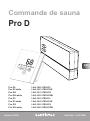
Sauna control unit
Pro D
Pro D2 1-041-288/PRO-D2
Pro D2 white 1-041-290/PRO-D2W
Pro D2i 1-041-291/PRO-D2I
Pro D2i white 1-041-292/PRO-D2IW
Pro D3 1-041-293/PRO-D3
D3 white 1-041-294/PRO-D3W
Pro D3i 1-041-295/PRO-D3I
D3i white 1-041-296/PRO-D2IW

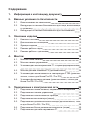
Table of Contents
1. About this instruction manual 6
2. Important information for your safety 7
2.1. Intended use 7
2.2. Safety information for the installer 8
2.3. Safety information for the user 9
3. Product description 10
3.1. Specicationssupplied 10
3.2. Optional accessories 10
3.3. Product functions 11
3.4. Sauna operating modes 15
3.5. Sensor operating modes 15
4. Installation 18
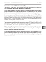
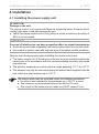
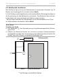
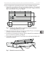
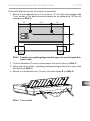
4.1. Installing the power supply unit 18
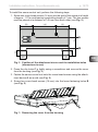
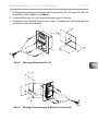
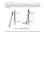
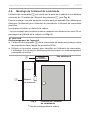
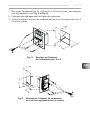
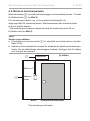
4.2. Installing the control panel 20
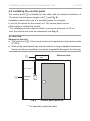
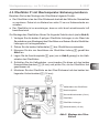
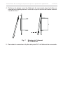
4.3. Installing the heater sensor F1 with overheat cut-out 23
4.4. Installing bench sensor F2 (optional) 24
4.5. Installing humidity sensor FTS2
(optional, only Pro D3/Pro D3i) 24
4.6. Installing foil sensor FTS2 (optional, only Pro D2i/Pro D3i) 25
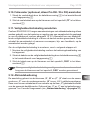
5. Electrical connection 26
5.1. Connecting the power supply cable, heater and evaporator 27
5.2. Connecting the control panel 28
5.3. Connecting the light 29
5.4. Connecting the fan (optional) 29
5.5. Connecting additional output (optional, only Pro D2i/Pro D3i) 29
5.6. Connecting the power booster (optional) 30
5.7. Connecting heater sensor F1 30

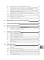
EN
5.8. Installing bench sensor F2 (optional) 30
5.9. Connecting humidity sensor FTS2
(optional, only Pro D3/Pro D3i) 30
5.10. Connecting foil sensor (optional, only Pro D2i/Pro D3i) 31
5.11. Connecting the safety cut-out 31
5.12. Remote start 31
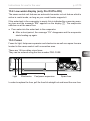
5.13. Status output 32
5.14. Finishing the installation 32
6. Performing tests 32
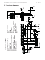
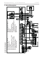
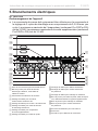
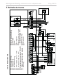
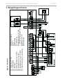
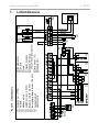
7. Terminal diagram 34
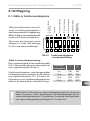
8. Commissioning 35
8.1. Setting the function selector switch 35
8.2. Settings on the technician menu 38
9. Controls 45
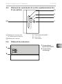
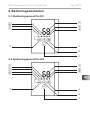
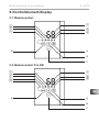
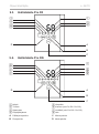
9.1. Control panel Pro D2 45
9.2. Control panel Pro D2i 45
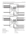
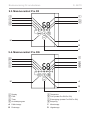
9.3. Control panel Pro D3 46
9.4. Control panel Pro D3i 46
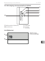
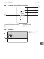
9.5. Additional output control panel Pro D (optional) 47
9.6. Power unit 47
10. Operation 48
10.1. Switching on the light on the power supply unit (cleaning lights) 48
10.2. Switching on the power unit 48
10.3. Activating the control panel 49
10.4. Additional output control panel Pro D (optional) 49
10.5. Starting sauna mode 50

10.6. Switchingosaunamode 50
10.7. Starting combi mode (only Pro D3/Pro D3i) 51
10.8. Switchingocombimode(onlyProD3/ProD3i) 51
10.9. Starting additional output (only Pro D2i/Pro D3i) 52
10.10.Switchingoadditionaloutput(optional,onlyProD2i/ProD3i) 54
10.11. Switching on the light 55
10.12.Switchingothelight 55
10.13. Starting the fan 56
10.14.Switchingothefan 56
10.15. Setting the preset time 57
10.16. Cancelling the preset time function 58
10.17. Setting the duration 58
10.18. Activating standby for remote operation 59
10.19. Changing the settings 59
10.20. Cancelling the post-drying program (only Pro D3/ProD3i) 60
10.21.Switchingofunctions 60
10.22. Deactivating the control panel 60
10.23.Switchingothepowersupplyunit 60
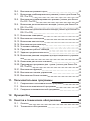
11. User programs 61
11.1. Preset user programs 61
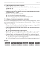
11.2. Accessing user programs 62
11.3. Creating your own user programs 62
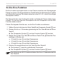
12. The Eco-function 64
13. Cleaning and maintenance 65
13.1. Cleaning 65
13.2. Maintenance 65

EN
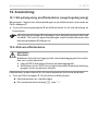
14. Disposal 65
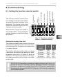
15. Troubleshooting 66
15.1. Error messages 66
15.2. Low-water display (only Pro D3/Pro D3i) 67
15.3. Fuses 67
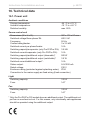
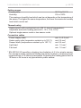
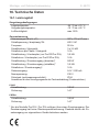
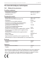
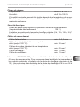
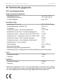
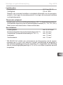
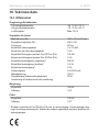
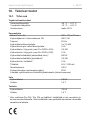
16. Technical data 68
16.1. Power unit 68
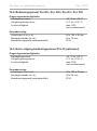
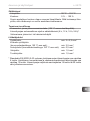
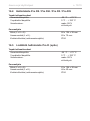
16.2. Control panel Pro D2/Pro D2i/Pro D3/Pro D3i 70
16.3. Additional output control panel Pro D (optional) 70

Instructions for installation and use p. 6/70
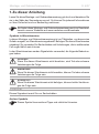
1. About this instruction manual
Read these installation and operating instructions carefully and keep them within
reach of the sauna control unit. This ensures that you can refer to information
about your safety and the operation at any time.
Symbols used for warning notices
In these instructions for installation and use, a warning notice located next to
an activity indicates that this activity poses a risk. Always observe the warning
notices. This prevents damage to property and injuries, which in the worst case
may be fatal.
The warning notices contain keywords, which have the following meanings:
DANGER!
Serious or fatal injury will occur if this warning notice is not observed.
WARNING!
Serious or fatal injury can occur if this warning notice is not observed.
CAUTION!
Minor injuries can occur if this warning notice is not observed.
ATTENTION!
This keyword is a warning that damage to property can occur.
Other symbols
This symbol indicates tips and useful information.
These installation and operating instructions can also be found in the
downloads section of our website: www.sentiotec.com/downloads.

EN
Instructions for installation and use p. 7/70
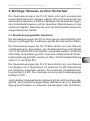
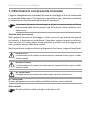
2. Important information for your safety
The sauna control units of the Pro D series have been produced
in accordance with the applicable safety rules and regulations.
However, hazards may occur during use. Therefore adhere to the
followingsafetyinformationandthespecicwarningnoticesin
the individual chapters. Also observe the safety information for the
devices connected.
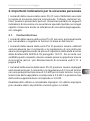
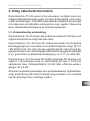
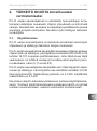
2.1. Intended use
The sauna control units of the Pro D series are used exclusively for
operating and controlling the sauna functions in accordance with
the technical data.
The sauna control units of the Pro D series may only be used for
operatingandcontrollingasaunaheaterwhichhasbeencertied
as satisfying the combustion test described in paragraph 19.101 of
EN 60335-2-53. If the heater does not meet this requirement, an
appropriate safety precaution must be taken (for example: safety
shut-o,see5.11onpage31).
The sauna control units of the Pro D series may only be used for
operating and controlling 3 heating circuits with a maximum heating
capacity of 3.5 kW per heating circuit. The maximum evaporator ca-
pacity is 3.5 kW. The maximum additional output capacity is 3.5 kW.
Any use exceeding this scope is considered improper use. Improper
use can result in damage to the product, severe injuries or death.

Instructions for installation and use p. 8/70
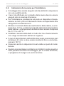
2.2. Safety information for the installer
●Installationmayonlybeperformedbyaqualiedelectricianor
similarlyqualiedperson.
●Work on the sauna control unit may only be performed when the
power has been disconnected.
●A fully disconnecting all-pole isolating device compliant with
overvoltagecategoryIIImustbettedon-site.
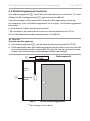
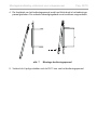
●The sauna control unit must be installed outside the sauna room
at a height of approx. 1.70 m or in accordance with the rec-
ommendation issued by the sauna manufacturer. The ambient
temperature must be within a range spanning -10 °C to +40 °C.
●The heater sensor must be attached in a way that it is not af-
fectedbyaowofair.
●The heater supply cable must have a minimum cross-sectional
area of 2.5 mm2 and be temperature resistant up to 150 °C.
●Any local regulations applicable at the installation location should
also be observed.
●For your own safety, consult your supplier in the event of prob-
lemsthatarenotexplainedinsucientdetailintheinstallation
instructions.

EN
Instructions for installation and use p. 9/70
2.3. Safety information for the user
●The sauna control unit must not be used by children under
8 years old.
●The sauna control unit may be used by children above 8 years
old, by persons with limited psychological, sensory or mental
capabilities or by persons with lack of experience/knowledge
only when:
– They are supervised.
– They have been shown how to use the device safely and
are aware of the hazards that could occur.
●Children must not play with the sauna control unit.
●Children under 14 years of age may only clean the sauna control
unit if they are supervised.
● Forhealthreasons,donotusethesaunawhenundertheinu-
ence of alcohol, medication or drugs.
●Make sure that no combustible objects have been placed on the
sauna heater before the sauna control unit is switched on.
●Make sure that no combustible objects have been placed on the
heater before activating the preset time function or the stand-by
mode for the remote start.
●Make sure that no combustible objects have been placed on
or in front of the infra-red lamp before the sauna control unit is
switched on.
●Make sure that no combustible objects have been placed on
the infra-red lamp before activating the preset time function or
the stand-by mode for the remote start.
●For your own safety, consult your supplier in the event of prob-
lemsthatarenotdescribedinsucientdetailintheoperating
instructions.

Instructions for installation and use p. 10/70
3. Product description
3.1. Specications supplied
●Operating unit (depending on version Pro D2/D2i/D3/D3i)
●Power unit
●Heater sensor with integrated overheat cut-out
●Sensor wires
●Installation material
●Wire jumper for bridging terminals V1 and Wm for combi heaters without
low-watershut-o
3.2. Optional accessories
●Bench sensor (1-009-231/O-F2), sensor cables 1.5 m
●Humidity temperature sensor (1-010-081/O-FTS2), sensor cables 3 m
●Foil sensor (1-014-445/P-ISX-FF), sensor cables 3 m
●Power booster (1-008-779/O-S2-18, 1-009-280/O-S2-30)
● Safetyshut-o(SFE-xxxxx)
●Operating unit Pro D2 (1-040-159/PRO-D2-CU)
●Operating unit Pro D2 white (1-040-161/PRO-D2W-CU)
●Operating unit Pro D2i (1-040-163/PRO-D2I-CU)
●Operating unit Pro D2i white (1-040-165/PRO-D2IW-CU)
●Operating unit Pro D3 (1-040-167/PRO-D3-CU)
●Operating unit Pro D3 white (1-040-169/PRO-D3W-CU)
●Operating unit Pro D3i (1-1040-173/PRO-D3I-CU)
●Operating unit Pro D3i white (1-1-040-173/PRO-D3IW-CU)
●Additional output control panel Pro D (1-040-174/PRO-DA-CU)
●Additional output control panel Pro D white (1-040-175/PRO-DAW-CU)
●Pro D BUS converter RS485 (1-045-317 / PRO-D-CON)
●ProNet web server (1-017-521 / PRO-NET)
●Remote start system (1-051-003 / FS-SY)
●Door sensor system (1-052-722 / SAB00102)

EN
Instructions for installation and use p. 11/70
3.3. Product functions
Pro D2/Pro D2 white
The sauna control unit Pro D2/Pro D2 white features the following functions:
●Regulation of sauna heaters with a heating output of up to 10.5 kW in the
temperature range spanning 30 °C to 110 °C.
●A power booster allows the maximum switching capacity to be increased from
10.5 kW to 18 kW or 30 kW.
●Optional dimming or activation of a cubicle light (up to 100 W)
●Optional dimmer function or activation of a fan (up to 100 W)
●Remote start function
●Status output
●Preset time function (up to 6 hours)
●User programs
The user programs enable favourite sauna settings to be saved and accessed
again.Thereare5presetuserprogramsavailablewhichcanbemodied
according to user requirements.
●Automatic heating period limiter
The sauna control unit shuts down automatically after the maximum heating
period for safety reasons. The maximum heating period can be set to 6 h,
12 h, 18 h or 24 h.
●Overheat cut-out
The overheat cut-out is installed in the housing for the heater sensor. Should
the sauna heater continue heating after reaching the preferred temperature
duetoadefect,theoverheatcut-outswitchesthesaunaheateroatatem-
perature of approx. 139 °C.

Instructions for installation and use p. 12/70
Pro D2i/Pro D2i white
Same functional scope as the Pro D2/Pro D2 white, however with further additions:
●Additional output
Either for dimming (up to 500 W), switching (up to 3.5 kW) or regulating the
sauna room temperature via the additional output.
The additional output has no overheat cut-out. For this reason, only intrinsi-
cally safe appliances should be operated using the additional output.
– If infra-red heaters are connected to the additional output, they must
have an overheat cut-out. We recommend using the following infra-
red lamps:
●1-027-780/ DIR-350-R, 1-027-845/WIR-350-R,
1-027-781/DIR-500-R, 1-027-846/WIR-500-R,
1-027-782/DIR-750-R, 1-027-847/WIR-750-R,
1-027-779/DIR-1300-R, 1-027-844/WIR-1300-R
●1-027-785/ECO-350-R, 1-027-784/ECO-350-G,
1-027-788/ECO-500-R, 1-027-787/ECO-500-G,
1-027-790/ECO-750-R
– If one of the following infra-red heater panels is connected to an ad-
ditional output, the foil sensor 1-014-445/P-ISX-FF must be used and
activated on the technician menu (see “Activating/deactivating foil
sensor (only Pro D2i/Pro D3i)” on page 39):
●1-028-348/IR-WP-100, 1-028-343/IR-WP-175,
1-028-784/IR-WP-390, 1-028-938/IR-WP-510
●1-028-149/IR-WPHL-100, 1-028-941/IR-WPHL-175,
1-028-601/IR-WPHL-390, 1-027-885/IR-WPHL-510

EN
Instructions for installation and use p. 13/70
Pro D3/Pro D3 white
The sauna control unit Pro D3/Pro D3 white features the following functions:
●Regulation of combi heaters with a heating output of up to 10.5 kW and
evaporator output of up to 3.5 kW in the temperature range spanning 30 °C
to 110 °C and a humidity range spanning 0% to 100%.
●A power booster allows the maximum switching capacity to be increased from
10.5 kW to 18 kW or 30 kW.
●Optional dimming or switching of a cublicle light (up to 100 W)
●Optional dimmer function or control of a fan (up to 100 W)
●Remote start function
●Status output
●Preset time function (up to 6 hours)
●User programs
The user programs enable favourite sauna settings to be saved and accessed
again.Thereare5presetuserprogramsavailablewhichcanbemodied
according to user requirements.
●Automatic heating period limiter
The sauna control unit shuts down automatically after the maximum heating
period for safety reasons. The maximum heating period can be set to 6 h,
12 h, 18 h or 24 h.
●Post-drying program
Oncecombi-modehasnished,thepost-dryingprogramstartsautomatically
to prevent mould or rot from forming in the sauna room. This involves heating
the sauna room to 80 °C with the fan running for 30 minutes.
●Overheat cut-out
The overheat cut-out is installed in the housing for the heater sensor. Should
the sauna heater continue heating after reaching the preferred temperature
duetoadefect,theoverheatcut-outswitchesthesaunaheateroatatem-
perature of approx. 139 °C.

Instructions for installation and use p. 14/70
Pro D3i/Pro D3i white
Same functional scope as the Pro D3/Pro D3 white, however with further additions:
●Additional output
Either for dimming (up to 500 W), switching (up to 3.5 kW) or regulating
the sauna room temperature via the additional output.
The additional output has no overheat cut-out. For this reason, only intrinsi-
cally safe appliances should be operated using the additional output.
– If infra-red heaters are connected to the additional output, they must
have an overheat cut-out. We recommend using the following infra-
red lamps:
●1-027-780/ DIR-350-R, 1-027-845/WIR-350-R,
1-027-781/DIR-500-R, 1-027-846/WIR-500-R,
1-027-782/DIR-750-R, 1-027-847/WIR-750-R,
1-027-779/DIR-1300-R, 1-027-844/WIR-1300-R
●1-027-785/ECO-350-R, 1-027-784/ECO-350-G,
1-027-788/ECO-500-R, 1-027-787/ECO-500-G,
1-027-790/ECO-750-R
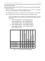
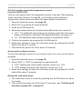
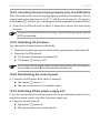
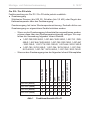
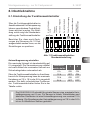
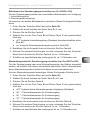
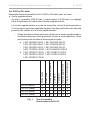
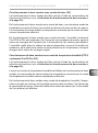
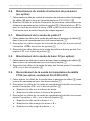
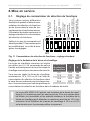
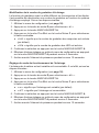
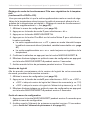
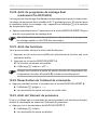
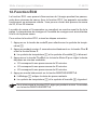
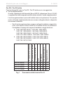
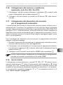
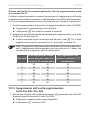
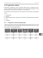
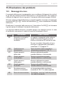
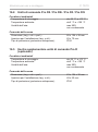
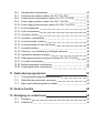
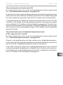
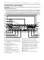
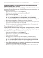
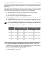
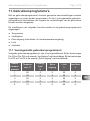
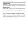
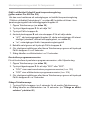
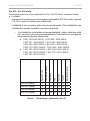
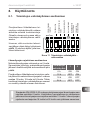
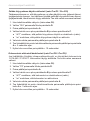
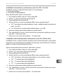
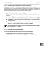
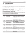
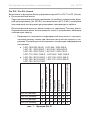
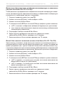
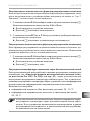
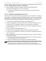
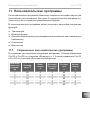
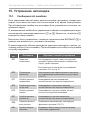
Sauna operating mode
Combi operating mode
Additional output
Light
Fan
Preset time
User programs
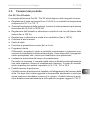
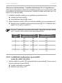
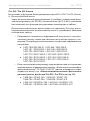
Pro D2 (white) X X X X X
Pro D2i (white) X X X X X X
Pro D3 (white) X X X X X X
Pro D3i (white) X X X X X X X
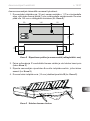
Fig. 1 Overview of Pro D functions

EN
Instructions for installation and use p. 15/70
– If one of the following infra-red heater panels is connected to an ad-
ditional output, the foil sensor 1-014-445/P-ISX-FF must be used and
activated on the technician menu (see “Activating/deactivating foil
sensor (only Pro D2i/Pro D3i)” on page 39):
●1-028-348/IR-WP-100, 1-028-343/IR-WP-175,
1-028-784/IR-WP-390, 1-028-938/IR-WP-510
●1-028-149/IR-WPHL-100, 1-028-941/IR-WPHL-175,
1-028-601/IR-WPHL-390, 1-027-885/IR-WPHL-510
3.4. Sauna operating modes
The sauna control unit Pro D2/Pro D2i enables sauna mode operation. The sauna
control unit Pro D3/Pro D3i provides two operating modes, sauna mode and
combi mode.
Sauna operating mode
Dry heat is provided in sauna mode. The temperature in the room is high
(80 to 100 °C) The humidity level of maximum 10% is low.
Combi mode
The evaporator operates along with the sauna heater in combi mode.
The temperature in the sauna room is lower (approx. 40 to 65 °C) than in sauna
mode, with the relative humidity being considerably higher, spanning 35% to
approximately 70%. The maximum humidity level which can be set depends on
the temperature of the sauna. The higher the sauna temperature, the lower the
maximum humidity level which can be set.

Instructions for installation and use p. 16/70
3.5. Sensor operating modes
The sauna control units of the Pro D series can be operated with one or
two sensors. A temperature sensor (bench sensor F2) or a humidity sensor
(FTS2, only Pro D3/Pro D3i) can be used as the second sensor.
Single-sensor mode (F1)
The single-sensor mode is activated at the factory. For changing this setting:
see “Activating two-sensor operation” on page 36.
In single-sensor mode, the sauna control unit is operated only with the heater sen-
sorwithoverheatcut-out(F1)only.Thisisincludedinthespecicationssupplied.
The sauna control unit displays the actual temperature by default. The set tem-
perature is displayed during setting. If it is to be permanently displayed it must be
activated during commissioning (see “Temperature/humidity display (actual/
set value)” on page 37)
The maximum humidity level (only Pro D3/Pro D3i) which can be set in single-
sensor mode is based on the temperature above the heater and the humidity
is timed. Only the set humidity level (in % of relative humidity) is shown on the
sauna control unit display. The actual humidity level in the sauna room when
humidity is timed depends on the size of the room and the evaporator capacity,
andmaydierfromthesetlevel.
Sidan laddas...
Sidan laddas...
Sidan laddas...
Sidan laddas...
Sidan laddas...
Sidan laddas...
Sidan laddas...
Sidan laddas...
Sidan laddas...
Sidan laddas...
Sidan laddas...
Sidan laddas...
Sidan laddas...
Sidan laddas...
Sidan laddas...
Sidan laddas...
Sidan laddas...
Sidan laddas...
Sidan laddas...
Sidan laddas...
Sidan laddas...
Sidan laddas...
Sidan laddas...
Sidan laddas...
Sidan laddas...
Sidan laddas...
Sidan laddas...
Sidan laddas...
Sidan laddas...
Sidan laddas...
Sidan laddas...
Sidan laddas...
Sidan laddas...
Sidan laddas...
Sidan laddas...
Sidan laddas...
Sidan laddas...
Sidan laddas...
Sidan laddas...
Sidan laddas...
Sidan laddas...
Sidan laddas...
Sidan laddas...
Sidan laddas...
Sidan laddas...
Sidan laddas...
Sidan laddas...
Sidan laddas...
Sidan laddas...
Sidan laddas...
Sidan laddas...
Sidan laddas...
Sidan laddas...
Sidan laddas...
Sidan laddas...
Sidan laddas...
Sidan laddas...
Sidan laddas...
Sidan laddas...
Sidan laddas...
Sidan laddas...
Sidan laddas...
Sidan laddas...
Sidan laddas...
Sidan laddas...
Sidan laddas...
Sidan laddas...
Sidan laddas...
Sidan laddas...
Sidan laddas...
Sidan laddas...
Sidan laddas...
Sidan laddas...
Sidan laddas...
Sidan laddas...
Sidan laddas...
Sidan laddas...
Sidan laddas...
Sidan laddas...
Sidan laddas...
Sidan laddas...
Sidan laddas...
Sidan laddas...
Sidan laddas...
Sidan laddas...
Sidan laddas...
Sidan laddas...
Sidan laddas...
Sidan laddas...
Sidan laddas...
Sidan laddas...
Sidan laddas...
Sidan laddas...
Sidan laddas...
Sidan laddas...
Sidan laddas...
Sidan laddas...
Sidan laddas...
Sidan laddas...
Sidan laddas...
Sidan laddas...
Sidan laddas...
Sidan laddas...
Sidan laddas...
Sidan laddas...
Sidan laddas...
Sidan laddas...
Sidan laddas...
Sidan laddas...
Sidan laddas...
Sidan laddas...
Sidan laddas...
Sidan laddas...
Sidan laddas...
Sidan laddas...
Sidan laddas...
Sidan laddas...
Sidan laddas...
Sidan laddas...
Sidan laddas...
Sidan laddas...
Sidan laddas...
Sidan laddas...
Sidan laddas...
Sidan laddas...
Sidan laddas...
Sidan laddas...
Sidan laddas...
Sidan laddas...
Sidan laddas...
Sidan laddas...
Sidan laddas...
Sidan laddas...
Sidan laddas...
Sidan laddas...
Sidan laddas...
Sidan laddas...
Sidan laddas...
Sidan laddas...
Sidan laddas...
Sidan laddas...
Sidan laddas...
Sidan laddas...
Sidan laddas...
Sidan laddas...
Sidan laddas...
Sidan laddas...
Sidan laddas...
Sidan laddas...
Sidan laddas...
Sidan laddas...
Sidan laddas...
Sidan laddas...
Sidan laddas...
Sidan laddas...
Sidan laddas...
Sidan laddas...
Sidan laddas...
Sidan laddas...
Sidan laddas...
Sidan laddas...
Sidan laddas...
Sidan laddas...
Sidan laddas...
Sidan laddas...
Sidan laddas...
Sidan laddas...
Sidan laddas...
Sidan laddas...
Sidan laddas...
Sidan laddas...
Sidan laddas...
Sidan laddas...
Sidan laddas...
Sidan laddas...
Sidan laddas...
Sidan laddas...
Sidan laddas...
Sidan laddas...
Sidan laddas...
Sidan laddas...
Sidan laddas...
Sidan laddas...
Sidan laddas...
Sidan laddas...
Sidan laddas...
Sidan laddas...
Sidan laddas...
Sidan laddas...
Sidan laddas...
Sidan laddas...
Sidan laddas...
Sidan laddas...
Sidan laddas...
Sidan laddas...
Sidan laddas...
Sidan laddas...
Sidan laddas...
Sidan laddas...
Sidan laddas...
Sidan laddas...
Sidan laddas...
Sidan laddas...
Sidan laddas...
Sidan laddas...
Sidan laddas...
Sidan laddas...
Sidan laddas...
Sidan laddas...
Sidan laddas...
Sidan laddas...
Sidan laddas...
Sidan laddas...
Sidan laddas...
Sidan laddas...
Sidan laddas...
Sidan laddas...
Sidan laddas...
Sidan laddas...
Sidan laddas...
Sidan laddas...
Sidan laddas...
Sidan laddas...
Sidan laddas...
Sidan laddas...
Sidan laddas...
Sidan laddas...
Sidan laddas...
Sidan laddas...
Sidan laddas...
Sidan laddas...
Sidan laddas...
Sidan laddas...
Sidan laddas...
Sidan laddas...
Sidan laddas...
Sidan laddas...
Sidan laddas...
Sidan laddas...
Sidan laddas...
Sidan laddas...
Sidan laddas...
Sidan laddas...
Sidan laddas...
Sidan laddas...
Sidan laddas...
Sidan laddas...
Sidan laddas...
Sidan laddas...
Sidan laddas...
Sidan laddas...
Sidan laddas...
Sidan laddas...
Sidan laddas...
Sidan laddas...
Sidan laddas...
Sidan laddas...
Sidan laddas...
Sidan laddas...
Sidan laddas...
Sidan laddas...
Sidan laddas...
Sidan laddas...
Sidan laddas...
Sidan laddas...
Sidan laddas...
Sidan laddas...
Sidan laddas...
Sidan laddas...
Sidan laddas...
Sidan laddas...
Sidan laddas...
Sidan laddas...
Sidan laddas...
Sidan laddas...
Sidan laddas...
Sidan laddas...
Sidan laddas...
Sidan laddas...
Sidan laddas...
Sidan laddas...
Sidan laddas...
Sidan laddas...
Sidan laddas...
Sidan laddas...
Sidan laddas...
Sidan laddas...
Sidan laddas...
Sidan laddas...
Sidan laddas...
Sidan laddas...
Sidan laddas...
Sidan laddas...
Sidan laddas...
Sidan laddas...
Sidan laddas...
Sidan laddas...
Sidan laddas...
Sidan laddas...
Sidan laddas...
Sidan laddas...
Sidan laddas...
Sidan laddas...
Sidan laddas...
Sidan laddas...
Sidan laddas...
Sidan laddas...
Sidan laddas...
Sidan laddas...
Sidan laddas...
Sidan laddas...
Sidan laddas...
Sidan laddas...
Sidan laddas...
Sidan laddas...
Sidan laddas...
Sidan laddas...
Sidan laddas...
Sidan laddas...
Sidan laddas...
Sidan laddas...
Sidan laddas...
Sidan laddas...
Sidan laddas...
Sidan laddas...
Sidan laddas...
Sidan laddas...
Sidan laddas...
Sidan laddas...
Sidan laddas...
Sidan laddas...
Sidan laddas...
Sidan laddas...
Sidan laddas...
Sidan laddas...
Sidan laddas...
Sidan laddas...
Sidan laddas...
Sidan laddas...
Sidan laddas...
Sidan laddas...
Sidan laddas...
Sidan laddas...
Sidan laddas...
Sidan laddas...
Sidan laddas...
Sidan laddas...
Sidan laddas...
Sidan laddas...
Sidan laddas...
Sidan laddas...
Sidan laddas...
Sidan laddas...
Sidan laddas...
Sidan laddas...
Sidan laddas...
Sidan laddas...
Sidan laddas...
Sidan laddas...
Sidan laddas...
Sidan laddas...
Sidan laddas...
Sidan laddas...
Sidan laddas...
Sidan laddas...
Sidan laddas...
Sidan laddas...
Sidan laddas...
Sidan laddas...
Sidan laddas...
Sidan laddas...
Sidan laddas...
Sidan laddas...
Sidan laddas...
Sidan laddas...
Sidan laddas...
Sidan laddas...
Sidan laddas...
Sidan laddas...
Sidan laddas...
Sidan laddas...
Sidan laddas...
Sidan laddas...
Sidan laddas...
Sidan laddas...
Sidan laddas...
Sidan laddas...
Sidan laddas...
Sidan laddas...
Sidan laddas...
Sidan laddas...
Sidan laddas...
Sidan laddas...
Sidan laddas...
Sidan laddas...
Sidan laddas...
Sidan laddas...
Sidan laddas...
Sidan laddas...
Sidan laddas...
Sidan laddas...
Sidan laddas...
Sidan laddas...
Sidan laddas...
Sidan laddas...
Sidan laddas...
Sidan laddas...
Sidan laddas...
Sidan laddas...
Sidan laddas...
Sidan laddas...
Sidan laddas...
Sidan laddas...
Sidan laddas...
Sidan laddas...
Sidan laddas...
Sidan laddas...
Sidan laddas...
Sidan laddas...
Sidan laddas...
Sidan laddas...
Sidan laddas...
Sidan laddas...
Sidan laddas...
Sidan laddas...
Sidan laddas...
Sidan laddas...
Sidan laddas...
Sidan laddas...
Sidan laddas...
Sidan laddas...
Sidan laddas...
Sidan laddas...
Sidan laddas...
Sidan laddas...
Sidan laddas...
Sidan laddas...
Sidan laddas...
Sidan laddas...
Sidan laddas...
Sidan laddas...
Sidan laddas...
Sidan laddas...
Sidan laddas...
Sidan laddas...
Sidan laddas...
Sidan laddas...
Sidan laddas...
Sidan laddas...
Sidan laddas...
Sidan laddas...
Sidan laddas...
Sidan laddas...
Sidan laddas...
Sidan laddas...
Sidan laddas...
Sidan laddas...
Sidan laddas...
Sidan laddas...
Sidan laddas...
Sidan laddas...
Sidan laddas...
Sidan laddas...
Sidan laddas...
Sidan laddas...
Sidan laddas...
Sidan laddas...
Sidan laddas...
Sidan laddas...
Sidan laddas...
Sidan laddas...
Sidan laddas...
Sidan laddas...
Sidan laddas...
Sidan laddas...
Sidan laddas...
Sidan laddas...
Sidan laddas...
Sidan laddas...
Sidan laddas...
Sidan laddas...
Sidan laddas...
Sidan laddas...
Sidan laddas...
Sidan laddas...
Sidan laddas...
Sidan laddas...
Sidan laddas...
Sidan laddas...
Sidan laddas...
Sidan laddas...
Sidan laddas...
Sidan laddas...
Sidan laddas...
Sidan laddas...
Sidan laddas...
Sidan laddas...
Sidan laddas...
Sidan laddas...
Sidan laddas...
Sidan laddas...
Sidan laddas...
Sidan laddas...
Sidan laddas...
Sidan laddas...
Sidan laddas...
Sidan laddas...
Sidan laddas...
Sidan laddas...
Sidan laddas...
Sidan laddas...
Sidan laddas...
Sidan laddas...
Sidan laddas...
Sidan laddas...
Sidan laddas...
Sidan laddas...
Sidan laddas...
Sidan laddas...
Sidan laddas...
Sidan laddas...
Sidan laddas...
Sidan laddas...
Sidan laddas...
Sidan laddas...
Sidan laddas...
Sidan laddas...
Sidan laddas...
Sidan laddas...
Sidan laddas...
Sidan laddas...
Sidan laddas...
Sidan laddas...
Sidan laddas...
Sidan laddas...
Sidan laddas...
Sidan laddas...
Sidan laddas...
Sidan laddas...
Sidan laddas...
Sidan laddas...
Sidan laddas...
Sidan laddas...
Sidan laddas...
Sidan laddas...
Sidan laddas...
-
 1
1
-
 2
2
-
 3
3
-
 4
4
-
 5
5
-
 6
6
-
 7
7
-
 8
8
-
 9
9
-
 10
10
-
 11
11
-
 12
12
-
 13
13
-
 14
14
-
 15
15
-
 16
16
-
 17
17
-
 18
18
-
 19
19
-
 20
20
-
 21
21
-
 22
22
-
 23
23
-
 24
24
-
 25
25
-
 26
26
-
 27
27
-
 28
28
-
 29
29
-
 30
30
-
 31
31
-
 32
32
-
 33
33
-
 34
34
-
 35
35
-
 36
36
-
 37
37
-
 38
38
-
 39
39
-
 40
40
-
 41
41
-
 42
42
-
 43
43
-
 44
44
-
 45
45
-
 46
46
-
 47
47
-
 48
48
-
 49
49
-
 50
50
-
 51
51
-
 52
52
-
 53
53
-
 54
54
-
 55
55
-
 56
56
-
 57
57
-
 58
58
-
 59
59
-
 60
60
-
 61
61
-
 62
62
-
 63
63
-
 64
64
-
 65
65
-
 66
66
-
 67
67
-
 68
68
-
 69
69
-
 70
70
-
 71
71
-
 72
72
-
 73
73
-
 74
74
-
 75
75
-
 76
76
-
 77
77
-
 78
78
-
 79
79
-
 80
80
-
 81
81
-
 82
82
-
 83
83
-
 84
84
-
 85
85
-
 86
86
-
 87
87
-
 88
88
-
 89
89
-
 90
90
-
 91
91
-
 92
92
-
 93
93
-
 94
94
-
 95
95
-
 96
96
-
 97
97
-
 98
98
-
 99
99
-
 100
100
-
 101
101
-
 102
102
-
 103
103
-
 104
104
-
 105
105
-
 106
106
-
 107
107
-
 108
108
-
 109
109
-
 110
110
-
 111
111
-
 112
112
-
 113
113
-
 114
114
-
 115
115
-
 116
116
-
 117
117
-
 118
118
-
 119
119
-
 120
120
-
 121
121
-
 122
122
-
 123
123
-
 124
124
-
 125
125
-
 126
126
-
 127
127
-
 128
128
-
 129
129
-
 130
130
-
 131
131
-
 132
132
-
 133
133
-
 134
134
-
 135
135
-
 136
136
-
 137
137
-
 138
138
-
 139
139
-
 140
140
-
 141
141
-
 142
142
-
 143
143
-
 144
144
-
 145
145
-
 146
146
-
 147
147
-
 148
148
-
 149
149
-
 150
150
-
 151
151
-
 152
152
-
 153
153
-
 154
154
-
 155
155
-
 156
156
-
 157
157
-
 158
158
-
 159
159
-
 160
160
-
 161
161
-
 162
162
-
 163
163
-
 164
164
-
 165
165
-
 166
166
-
 167
167
-
 168
168
-
 169
169
-
 170
170
-
 171
171
-
 172
172
-
 173
173
-
 174
174
-
 175
175
-
 176
176
-
 177
177
-
 178
178
-
 179
179
-
 180
180
-
 181
181
-
 182
182
-
 183
183
-
 184
184
-
 185
185
-
 186
186
-
 187
187
-
 188
188
-
 189
189
-
 190
190
-
 191
191
-
 192
192
-
 193
193
-
 194
194
-
 195
195
-
 196
196
-
 197
197
-
 198
198
-
 199
199
-
 200
200
-
 201
201
-
 202
202
-
 203
203
-
 204
204
-
 205
205
-
 206
206
-
 207
207
-
 208
208
-
 209
209
-
 210
210
-
 211
211
-
 212
212
-
 213
213
-
 214
214
-
 215
215
-
 216
216
-
 217
217
-
 218
218
-
 219
219
-
 220
220
-
 221
221
-
 222
222
-
 223
223
-
 224
224
-
 225
225
-
 226
226
-
 227
227
-
 228
228
-
 229
229
-
 230
230
-
 231
231
-
 232
232
-
 233
233
-
 234
234
-
 235
235
-
 236
236
-
 237
237
-
 238
238
-
 239
239
-
 240
240
-
 241
241
-
 242
242
-
 243
243
-
 244
244
-
 245
245
-
 246
246
-
 247
247
-
 248
248
-
 249
249
-
 250
250
-
 251
251
-
 252
252
-
 253
253
-
 254
254
-
 255
255
-
 256
256
-
 257
257
-
 258
258
-
 259
259
-
 260
260
-
 261
261
-
 262
262
-
 263
263
-
 264
264
-
 265
265
-
 266
266
-
 267
267
-
 268
268
-
 269
269
-
 270
270
-
 271
271
-
 272
272
-
 273
273
-
 274
274
-
 275
275
-
 276
276
-
 277
277
-
 278
278
-
 279
279
-
 280
280
-
 281
281
-
 282
282
-
 283
283
-
 284
284
-
 285
285
-
 286
286
-
 287
287
-
 288
288
-
 289
289
-
 290
290
-
 291
291
-
 292
292
-
 293
293
-
 294
294
-
 295
295
-
 296
296
-
 297
297
-
 298
298
-
 299
299
-
 300
300
-
 301
301
-
 302
302
-
 303
303
-
 304
304
-
 305
305
-
 306
306
-
 307
307
-
 308
308
-
 309
309
-
 310
310
-
 311
311
-
 312
312
-
 313
313
-
 314
314
-
 315
315
-
 316
316
-
 317
317
-
 318
318
-
 319
319
-
 320
320
-
 321
321
-
 322
322
-
 323
323
-
 324
324
-
 325
325
-
 326
326
-
 327
327
-
 328
328
-
 329
329
-
 330
330
-
 331
331
-
 332
332
-
 333
333
-
 334
334
-
 335
335
-
 336
336
-
 337
337
-
 338
338
-
 339
339
-
 340
340
-
 341
341
-
 342
342
-
 343
343
-
 344
344
-
 345
345
-
 346
346
-
 347
347
-
 348
348
-
 349
349
-
 350
350
-
 351
351
-
 352
352
-
 353
353
-
 354
354
-
 355
355
-
 356
356
-
 357
357
-
 358
358
-
 359
359
-
 360
360
-
 361
361
-
 362
362
-
 363
363
-
 364
364
-
 365
365
-
 366
366
-
 367
367
-
 368
368
-
 369
369
-
 370
370
-
 371
371
-
 372
372
-
 373
373
-
 374
374
-
 375
375
-
 376
376
-
 377
377
-
 378
378
-
 379
379
-
 380
380
-
 381
381
-
 382
382
-
 383
383
-
 384
384
-
 385
385
-
 386
386
-
 387
387
-
 388
388
-
 389
389
-
 390
390
-
 391
391
-
 392
392
-
 393
393
-
 394
394
-
 395
395
-
 396
396
-
 397
397
-
 398
398
-
 399
399
-
 400
400
-
 401
401
-
 402
402
-
 403
403
-
 404
404
-
 405
405
-
 406
406
-
 407
407
-
 408
408
-
 409
409
-
 410
410
-
 411
411
-
 412
412
-
 413
413
-
 414
414
-
 415
415
-
 416
416
-
 417
417
-
 418
418
-
 419
419
-
 420
420
-
 421
421
-
 422
422
-
 423
423
-
 424
424
-
 425
425
-
 426
426
-
 427
427
-
 428
428
-
 429
429
-
 430
430
-
 431
431
-
 432
432
-
 433
433
-
 434
434
-
 435
435
-
 436
436
-
 437
437
-
 438
438
-
 439
439
-
 440
440
-
 441
441
-
 442
442
-
 443
443
-
 444
444
-
 445
445
-
 446
446
-
 447
447
-
 448
448
-
 449
449
-
 450
450
-
 451
451
-
 452
452
-
 453
453
-
 454
454
-
 455
455
-
 456
456
-
 457
457
-
 458
458
-
 459
459
-
 460
460
-
 461
461
-
 462
462
-
 463
463
-
 464
464
-
 465
465
-
 466
466
-
 467
467
-
 468
468
-
 469
469
-
 470
470
-
 471
471
-
 472
472
-
 473
473
-
 474
474
-
 475
475
-
 476
476
-
 477
477
-
 478
478
-
 479
479
-
 480
480
-
 481
481
-
 482
482
-
 483
483
-
 484
484
-
 485
485
-
 486
486
-
 487
487
-
 488
488
-
 489
489
-
 490
490
-
 491
491
-
 492
492
-
 493
493
-
 494
494
-
 495
495
-
 496
496
-
 497
497
-
 498
498
-
 499
499
-
 500
500
-
 501
501
-
 502
502
-
 503
503
-
 504
504
-
 505
505
-
 506
506
-
 507
507
-
 508
508
-
 509
509
-
 510
510
-
 511
511
-
 512
512
-
 513
513
-
 514
514
-
 515
515
-
 516
516
-
 517
517
-
 518
518
-
 519
519
-
 520
520
-
 521
521
-
 522
522
-
 523
523
-
 524
524
-
 525
525
-
 526
526
-
 527
527
-
 528
528
-
 529
529
-
 530
530
-
 531
531
-
 532
532
-
 533
533
-
 534
534
-
 535
535
-
 536
536
-
 537
537
-
 538
538
-
 539
539
-
 540
540
-
 541
541
-
 542
542
-
 543
543
-
 544
544
-
 545
545
-
 546
546
-
 547
547
-
 548
548
-
 549
549
-
 550
550
-
 551
551
-
 552
552
-
 553
553
-
 554
554
-
 555
555
-
 556
556
-
 557
557
-
 558
558
-
 559
559
-
 560
560
-
 561
561
-
 562
562
-
 563
563
-
 564
564
-
 565
565
-
 566
566


på andra språk
- italiano: Sentiotec Pro D Manuale utente
- français: Sentiotec Pro D Manuel utilisateur
- English: Sentiotec Pro D User manual
- Nederlands: Sentiotec Pro D Handleiding
Relaterade papper
-
Sentiotec Pro D Användarmanual
-
-
-
-
-
-
-
Sentiotec Concept R combi Användarmanual
-
-
HARVIA SENTIO pronet Användarmanual
Andra dokument
-
-
-
-
-
HARVIA SW90E Instructions For Installation And Use Manual
-
HUUM GSM/ Wi-Fi/ Local Heater Control Console Användarmanual
-
Tylö Control Panel Pure#hs_cos_wrapper_module_170083095099537 .icon-style--link .g-module-macros-icon { padding-left:8px; } #hs_cos_wrapper_module_170083095099537 .icon-style--link .g-module-macros-icon svg { fill:#C65622; } Bruksanvisning