Sentiotec Concept R combi Användarmanual
- Typ
- Användarmanual

Version 07/23 Ident no CP-RCB-MA
INSTRUCTIONS FOR INSTALLATION AND USE
English EN
DE
FR
IT
NL
SV
CS
SL
FI
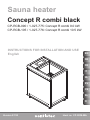
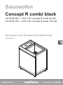
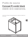
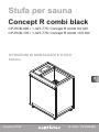
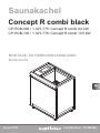
Sauna heater
Concept R combi black
CP-RCB-090 / 1-027-775: Concept R combi 9.0 kW
CP-RCB-105 / 1-027-776: Concept R combi 10.5 kW

Table of Contents
1. About this instruction manual 4
2. Important information for your safety 5
2.1. Intended use 5
2.2. Safety information for the installer 6
2.3. Safety information for the user 7
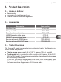
3. Product description 9
3.1. Scope of delivery 9
3.2. Accessories 9
3.3. Product functions 9
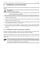
4. Installation and connection 10
4.1. Installation location and sensor position 10
4.2. Safety distances 11
4.3. Adjusting the height 11
4.4. Connection diagram for 400 V 3N~ 12
4.5. Connection diagram for 230 V 1N~ 13
4.6. Electrical connection 14
5. Commissioning 16
5.1. Filling the stone container 16
5.2. Inserting the ceramic bowl 16
5.3.Heatingforthersttime 17
6. Operation 18
6.1. Finnish sauna mode 18
6.2. Combi mode 19

EN
7. Maintenance 21
7.1. Extended periods of non-use 21
7.2. Cleaning the sauna heater 21
7.3. Changing the sauna stones 21
7.4. Cleaning the evaporator tank 22
7.5. Cleaning the ceramic bowl 22
7.6. Descaling the evaporator tank 23
8. Problem-solving by the installer 23
9. Disposal 23
10. Technical data 24
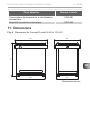
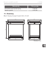
11. Dimensions 25

Instructions for installation and use p. 4/26
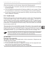
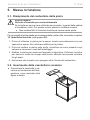
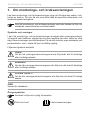
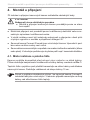
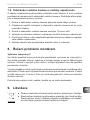
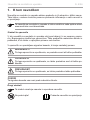
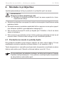
1. About this instruction manual
Carefully read these instructions for installation and use, and keep them near
the sauna. This ensures that you can refer to information about your safety and
the operation at any time.
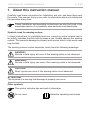
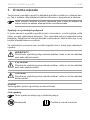
Symbols used for warning notices
In these instructions for installation and use, a warning notice located next to
an activity indicates that this activity poses a risk. Always observe the warning
notices. This prevents damage to property and injuries, which in the worst case
may be fatal.
The warning notices contain keywords, which have the following meanings:
DANGER!
Serious or fatal injury will occur if this warning notice is not observed.
WARNING!
Serious or fatal injury can occur if this warning notice is not observed.
CAUTION!
Minor injuries can occur if this warning notice is not observed.
ATTENTION!
This keyword is a warning that damage to property can occur.
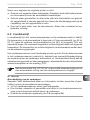
Other symbols
This symbol indicates tips and useful information.
Do not cover Read the operating instructions
These installation and operating instructions can also be found in the
downloads section of our website: www.sentiotec.com/downloads.

EN
Instructions for installation and use p. 5/26
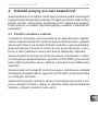
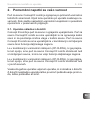
2. Important information for your safety
The Concept R combi sauna heater has been produced in accord-
ance with the applicable safety rules and regulations. However,
hazards may occur during use. Therefore adhere to the following
safetyinformationandthespecicwarningnoticesintheindividual
chapters.
2.1. Intended use
The Concept R combi is a sauna heater with integrated evaporator.
The Concept R combi is intended solely for heating sauna cabins
and for increasing the humidity within the sauna cabin. The Concept
R combi may only be used in conjunction with a sauna control unit
without a remote start function.
The Concept R combi sauna heater can also be used with a sauna
control unit with a remote start function, but only in conjunction with
the optional safety shutdown feature (CP-R-SWL).
The Concept R combi sauna heater can also be used in public
saunas, but only in conjunction with the optional safety shutdown
feature (CP-R-SWL).
Any use exceeding this scope is considered improper use. Improper
use can result in damage to the product, severe injuries or death.

Instructions for installation and use p. 6/26
2.2. Safety information for the installer
●Installing and connecting the sauna heater may only be performed
when the power supply is disconnected.
●Installationmayonlybeperformedbyaqualiedelectricianor
similarlyqualiedperson.
●A fully disconnecting all-pole isolating device compliant with
overvoltagecategoryIIImustbettedonsite.
●Always use silicone cables that are heat-resistant up to 150 °C
to connect the sauna heater.
●Only install one sauna heater in the cabin. The Concept R combi
sauna heater must not be used together with other sauna heaters
in a sauna cabin.
●The roof and walls of the sauna cabin must be manufactured
from low-resin, untreated or thermally treated wood, e.g. Nordic
spruce,hemlock,pineorr,orfromlaminatedwoodenmateri-
als. If laminated wooden materials are used, make sure that the
adhesiveusedinthemdoesnotgiveoformaldehyde.Ifother
materials than wood are used in the sauna cabin, these materi-
als must be heat-resistant and corrosion-resistant and must not
causeanynegativeeectsonthehealthofthesaunausers.
●The height of the sauna cabin must be at least 2.0 m.
● Observethespecicationsonvolumesandonventilationofthe
sauna cabin in chapter 10. Technical data on page 24.
●When positioning the sauna heater, observe the minimum safety
distances (see chapter 4.2. Safety distances on page 11).
●Also comply with the regulations applicable at the installation
location.
●For your own safety, consult your supplier in the event of prob-
lemsthatarenotexplainedinsucientdetailintheinstallation
instructions.

EN
Instructions for installation and use p. 7/26
2.3. Safety information for the user
●The device must not be used by children under 8 years of age.
●The device may only be used by children over 8 years of age,
by persons with limited psychological, sensory or mental capa-
bilities or by persons with lack of experience/knowledge under
the following conditions:
– They are supervised.
– They have been shown how to use the device safely and
are aware of the hazards that could occur.
●Children must not play with the device.
●Children under 14 years of age may only clean the device if they
are supervised.
● Forhealthreasons,donotusethesaunawhenundertheinu-
ence of alcohol, medication or drugs.
●Never operate the sauna heater without sauna stones, as this
cancauseres.
●Heat up the sauna heater and the evaporator for half an hour
BEFOREusingthesaunaforthersttime.DoNOTremainin
the sauna cabin during this period. Then ventilate the sauna
cabin well (see 5.3. Heating for the rst time on page 17).
● Makesurethatnoammableobjectshavebeenplacedonthe
sauna heater before the sauna control unit is switched on.

Instructions for installation and use p. 8/26
●Never touch the sauna heater while it is operating. The surfaces
of the sauna heater and sauna stones become extremely hot.
●NEVERpourwaterintothehotevaporatortank.Checkandll
the evaporator tank each time before starting combi mode. If the
overheatingprotectionhasswitchedoevaporatorheating,orif
your sauna control unit reports a lack of water, allow the evaporator
to cool down BEFORE you pour water into the evaporator tank.
●For your own safety, consult your supplier in the event of problems
thatarenotdescribedinsucientdetailintheuserinstructions.

EN
Instructions for installation and use p. 9/26
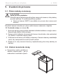
3. Product description
3.1. Scope of delivery
●Sauna heater
●Instructions for installation and use
●Ceramic bowl for herbs and fragrances
3.2. Accessories
Accessories Item number
AutoRellSet CP-RC-AF
Safetyshut-o CP-R-SWL
Bracket set for heater railing CP-R-HSR
LINDEN wooden railing, large CP-R-L2
WALNUT wooden railing, large CP-R-N2
Emotion railingset LINDEN, large CPR-EMO-L2
Emotion railingset WALNUT, large CPR-EMO-N2
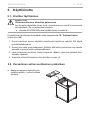
3.3. Product functions
The Concept R combi sauna heater is a combination heater. The following op-
erating modes are possible:
●Finnish sauna mode: usually 80 to 100 °C; approx. 10% rel. humidity
●Combi mode (only in combination with a combi control): approx. 40 to 65 °C,
35% to 70% humidity. The maximum permissible relative humidity decreases
with increasing temperature.
If you wish, you can put fragrances or dried herbs in the ceramic bowl over
the evaporator in combi mode. The rising steam releases essential oils from
theherbsandallowsfragrancestollthesaunacabin.

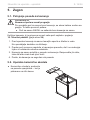
Installation instructions, only for experts p. 10/26
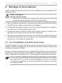
4. Installation and connection
Take the following points into account when positioning and connecting the sauna
heater:
Ifthereissucientventilation,theConceptRsaunaheatercanalsobe
setupasafree-standingdevice.Inthiscase,tthetemperaturesensor
to the cabin roof above the centre of the heater.
●Theelectricalconnectionmayonlybeperformedbyaqualiedelectricianor
similarlyqualiedperson.
●A fully disconnecting all-pole isolating device compliant with overvoltage
categoryIIImustbettedonsite.
●The Concept R combi sauna heater is a free-standing heater. It does not need
tobeattachedtotheoororsaunawall.
●Donotplacethesaunaheateronaoormadefromaneasilyammable
materialsuchaswoodorplastic.Suitableooringincludesceramictiles,for
example.
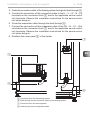
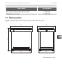
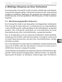
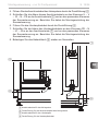
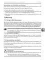
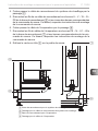
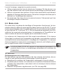
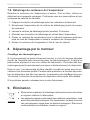
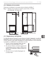
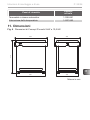
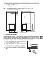
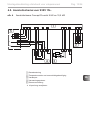
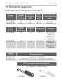
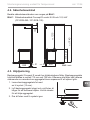
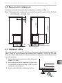
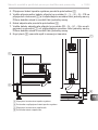
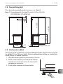
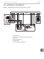
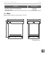
4.1. Installation location and sensor position
Position the heater centrally in front of the air intake opening in the cabin wall.
ObservethesafetydistancestothecabinwallspeciedinFig. 1.
Install the temperature sensor with excess temperature cut-out to the cabin wall
above the centre of the sauna heater. Maintain a distance of 15 cm to the sauna
cabin roof.
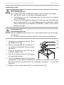
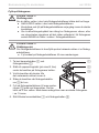
WARNING!
Danger of electric shock
●The sauna heater may only be installed and connected when the
power supply is disconnected.

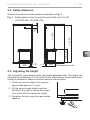
min.
1940
450
min.
50
715-725
min.
50
150
590
min.
1215
EN
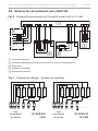
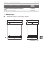
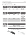
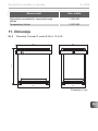
Installation instructions, only for experts p. 11/26
Fig. 1 Safety distances for Concept R combi 9 kW and 10.5 kW
(CP-RCB-090 / CP-RCB-105)
4.2. Safety distances
ObservetheminimumsafetydistancesspeciedinFig. 1.
Dimensions in mm
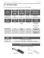
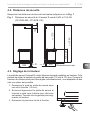
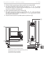
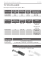
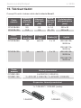
4.3. Adjusting the height
The Concept R combi sauna heater has height-adjustable feet. The height can
therefore be set between 715 mm and 725 mm. Each foot can be set individually,
makingitpossibletoadaptthesaunaheatertounevenoors.
1. Loosen the sauna heater foot using an
open-ended spanner (13 mm).
2. Lift the sauna heater slightly and turn
the foot to the right to reduce the height.
Turn to the left to increase the height.
3. Retighten the foot using the open-ended
spanner.

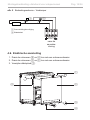
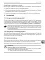
L1 L2 N
L3 U
V
N
Wr
r
w
w
ϑϑ
U
V
NW
W
400V 3N~
NVNU
PE
N
N
V1
Wm
N
U1
WM
L2
L1
L3
Installation instructions, only for experts p. 12/26
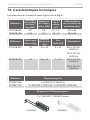
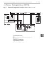
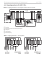
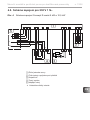
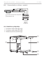
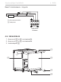
4.4. Connection diagram for 400 V 3N~
Fig. 2 Connection diagram for Concept R combi 9 kW and 10.5 kW
2
34
1 Sauna control unit
2 Temperature sensor with excess temperature cut-out
3 Evaporator
4 Heating system
5 Power supply
1
5
Fig. 3 Wiring diagrams – heating system
1,5 kW
1,5 kW
1,5 kW
U V W
1,5 kW
1,5 kW
1,5 kW
CP-R-090
9,0 kW
N N N
W V U
1,5 kW
2,0 kW
1,5 kW
U V W
2,0 kW
1,5 kW
2,0 kW
CP-R-105
10,5 kW
N N N
W V U
To the
sauna
control unit
To the
sauna
control unit
CP-RCB-090
9 kW
CP-RCB-105
10.5 kW

EN
Installation instructions, only for experts p. 13/26
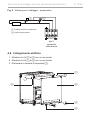
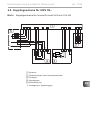
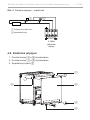
4
4.5. Connection diagram for 230 V 1N~
Fig. 4
2
3
5
1
Connection diagram for Concept R combi 9 kW and 10.5 kW
1 Sauna control unit
2 Temperature sensor with excess temperature cut-out
3 Evaporator
4 Heating system
5 Power supply
Remove the copper bridge
*
*
L1 L2 N
L3 U
V
N
Wr
r
w
w
ϑϑ
U
V
NW
W
230V 1N~
NVNU
L
PE
N
N
V1
Wm
N
U1
WM
1

Installation instructions, only for experts p. 14/26
U1
N
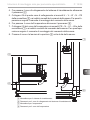
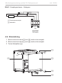
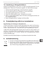
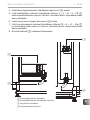
4.6. Electrical connection
1. Unscrew the screws 3 and 4 with a screwdriver.
2. Unscrew the screws 1 and 5 with a screwdriver.
3. Remove the cover plate 2.
1
2
3
4
5
Fig. 5 Wiring diagram – evaporator
To the
sauna
control unit
12
1 Excess temperature cut-out
2 Lack of water

EN
Installation instructions, only for experts p. 15/26
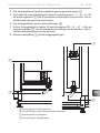
4. Guide the connection cable of the heating system through the feed-through 6.
5. Connect the connectors of this connection cable to the U – V – W – N – PE
terminals on the connector block 5 and to the applicable sauna control
unit terminals. Observe the installation instructions for the sauna control
unit when doing so.
6. Guide the evaporator cable through the feed-through 8.
7. Connect the connectors of this evaporator cable to the PE – N – U1 – Wm
terminals on the connector block 7 and to the applicable sauna control
unit terminals. Observe the installation instructions for the sauna control
unit when doing so.
8. Reattach the cover panel 2 to the heater.
7
8
5
6
5 Connector block for the heating system
6 Feed-through for the connection cable of the heating system
7 Connector block for the evaporator
8 Feed-through for the evaporator cable

Instructions for use for the user p. 16/26
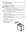
5. Commissioning
5.1. Filling the stone container
The amount of stones suited to your heater output can be found
in chapter 10. Technical data (see page 24).
1. Wash the stones thoroughly using water and a brush before use. Do not
use any cleaning additives.
2. Beforellingtheheaterwiththesaunastones,checkthemforforeignobjects
and remove any remaining packaging.
3. Place the stones in the stone container. Stack the sauna stones loosely so
thataircanowthroughthegaps.
4. Make sure that the sauna stones do not protrude beyond the edge of the
stone container.
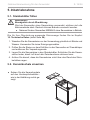
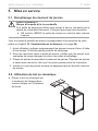
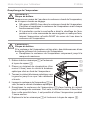
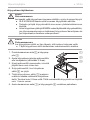
5.2. Inserting the ceramic bowl
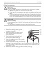
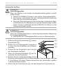
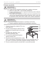
WARNING!
Risk of re due to overheating
If the sauna heater is used without sauna stones, the cabin walls will
becomeextremelyhot.Thiscouldcauseres.
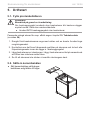
●NEVER operate the sauna heater without the sauna stones.
●Place the ceramic bowl on the
evaporator tank as shown in the
illustration on the right.

EN
Instructions for use for the user p. 17/26
5.3. Heating for the rst time
CAUTION!
Formation of smoke and odours when heating up for the rst time
Materials used during the manufacturing process will be present on the
new heating elements. These evaporate when the sauna heater is heat-
edupforthersttime.Thisproducessmokeandanunpleasantodour.
Breathing in the fumes or smoke can be harmful to your health.
Perform the following steps when operating the sauna heater for the rst
time and if the heating elements for the sauna heater have been replaced.
This prevents damage to health due to the fumes and smoke produced when
heatingforthersttime.
1. Heatingtheheatingrodsforthersttime
a. Select the highest possible temperature on the sauna control unit.
b. Heat up the sauna heater for half an hour.
Do NOT remain in the sauna cabin during this period.
2. Heatingtheevaporatorforthersttime
a. Select a low temperature and high humidity on the sauna control unit.
b. Heat up the evaporator with half the amount of water (see page 20)
Do NOT remain in the sauna cabin during this period.
c. Switchothesaunacontrolunitafterapprox.15minutes.
d. Allow the evaporator to cool (for approx. half an hour).
e. Empty the water tank (see Filling the evaporator on page 20)
f. Repeat step 2.b.
g. Allow the sauna cabin to ventilate thoroughly after heating for
thersttime.
h. If no smoke or odours form the next time the sauna heater is heated,
you can start to use the sauna.
If smoke or odour is produced again, leave the sauna cabin immedi-
ately and repeat the initial heating up process followed by ventilation.

Instructions for use for the user p. 18/26
A sauna control unit is used to operate the sauna heater. For information on how
to operate the sauna control unit, read the operating instructions for the device
used. Please note that only sauna control units without a remote start function
are permitted for use with the Concept R combi sauna heater.
6. Operation
WARNING!
Risk of re
Combustible objects that are placed on the heater will ignite and cause
res.
●NEVER place combustible objects on the sauna heater.
●MakesurethatNOammableobjectshavebeenplacedonthe
heater before operating it.
6.1. Finnish sauna mode
In Finnish sauna mode, only the heating system operates. Dry heat is produced.
The temperature in the cabin is high (80 to 100 °C). The maximum humidity level
of 10% is low. The temperature in the sauna cabin is regulated by your sauna
control unit.
At the end of the sauna session, you can pour an infusion of water over the
stones. Pour water over the stones using a sauna ladle. The water evaporates
and the humidity in the sauna cabin increases.
With the optional safety shutdown feature (CP-R-SWL), the Concept
R combi sauna heater is also suitable for sauna control units WITH
a remote start function.

EN
Instructions for use for the user p. 19/26
TheAutoRellSet(CP-RC-AF)allowsforaxedwaterconnection,
makingitpossibletolltheevaporatortankautomatically.
When pouring water over the stones, observe the following points:
●Only use tap water. Sea water, hard water and chlorinated water can damage
the sauna heater.
●Only use fragrances and essential oils that are suitable for use in saunas. Follow
the manufacturer’s instructions on the packaging of the scented substance.
●Do not pour the water onto the stones too quickly. Only this way will all the
water evaporate completely.
6.2. Combi mode
Both the heating system and evaporator operate in combi mode. The temperature
in the sauna cabin is lower than in Finnish sauna mode (approx. 40 to 65 °C),
with the relative humidity being considerably higher at 35% to approximately
70%. The maximum permissible relative humidity decreases with increasing
temperature. The temperature and the humidity in the sauna cabin are controlled
by your sauna control unit.
Theevaporatortankmustbelledmanually.Ifthewaterintheevaporatortank
hasbeenusedup,anoverheatingprotectionfunctionautomaticallyturnsothe
heating of the evaporator. The lack of water is reported to the sauna control unit
and displayed there, e.g. by an audible warning tone and the message “FILL”.
ATTENTION!
Damage to the evaporator
Sea water, hard water, chlorinated water, herbs, essences or fragrances can
damage the sauna heater.
● Onlylltheevaporatortankwithtapwater.
●Do not put herbs, essences or fragrances directly into the evaporator tank,
and only into the ceramic bowl over the evaporator.
●Descale the evaporator regularly (see 7.6. on page 24).

Instructions for use for the user p. 20/26
CAUTION!
Risk of scalding
If you pour water into the hot evaporator tank, hot steam is created.
●NEVER pour water into the hot evaporator tank.
● Checkandlltheevaporatortankeachtimebeforestartingcombi
mode.
●Iftheoverheatingprotectionhasswitchedoevaporatorheating,or
if your sauna control unit reports a lack of water, allow the evapora-
tor to cool down BEFORE you pour water into the evaporator tank.
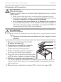
Filling the evaporator
CAUTION!
Risk of scalding
If the evaporator tank is too full, boiling water will spray out of the evap-
orator tank.
● Onlylltheevaporatortankuptothemaximummark.
1. Remove the ceramic bowl 1 and
the steam funnel 2.
2. Place a receptacle (at least 5 litres)
under the ball valve at the bottom
of the evaporator.
3. Turn the ball valve to the left until
theremainingwaterowsout.
4. When the evaporator tank 3 is empty,
close the ball valve.
5. Fill the evaporator tank 3 with fresh tap
1
water up to the maximum mark. You will need about 5 litres of water for
this. This amount of water allows the evaporator to be operated for ap-
proximately 1 hour.
6. Replace the ceramic bowl 1 and the steam funnel 2.
2
3
Sidan laddas...
Sidan laddas...
Sidan laddas...
Sidan laddas...
Sidan laddas...
Sidan laddas...
Sidan laddas...
Sidan laddas...
Sidan laddas...
Sidan laddas...
Sidan laddas...
Sidan laddas...
Sidan laddas...
Sidan laddas...
Sidan laddas...
Sidan laddas...
Sidan laddas...
Sidan laddas...
Sidan laddas...
Sidan laddas...
Sidan laddas...
Sidan laddas...
Sidan laddas...
Sidan laddas...
Sidan laddas...
Sidan laddas...
Sidan laddas...
Sidan laddas...
Sidan laddas...
Sidan laddas...
Sidan laddas...
Sidan laddas...
Sidan laddas...
Sidan laddas...
Sidan laddas...
Sidan laddas...
Sidan laddas...
Sidan laddas...
Sidan laddas...
Sidan laddas...
Sidan laddas...
Sidan laddas...
Sidan laddas...
Sidan laddas...
Sidan laddas...
Sidan laddas...
Sidan laddas...
Sidan laddas...
Sidan laddas...
Sidan laddas...
Sidan laddas...
Sidan laddas...
Sidan laddas...
Sidan laddas...
Sidan laddas...
Sidan laddas...
Sidan laddas...
Sidan laddas...
Sidan laddas...
Sidan laddas...
Sidan laddas...
Sidan laddas...
Sidan laddas...
Sidan laddas...
Sidan laddas...
Sidan laddas...
Sidan laddas...
Sidan laddas...
Sidan laddas...
Sidan laddas...
Sidan laddas...
Sidan laddas...
Sidan laddas...
Sidan laddas...
Sidan laddas...
Sidan laddas...
Sidan laddas...
Sidan laddas...
Sidan laddas...
Sidan laddas...
Sidan laddas...
Sidan laddas...
Sidan laddas...
Sidan laddas...
Sidan laddas...
Sidan laddas...
Sidan laddas...
Sidan laddas...
Sidan laddas...
Sidan laddas...
Sidan laddas...
Sidan laddas...
Sidan laddas...
Sidan laddas...
Sidan laddas...
Sidan laddas...
Sidan laddas...
Sidan laddas...
Sidan laddas...
Sidan laddas...
Sidan laddas...
Sidan laddas...
Sidan laddas...
Sidan laddas...
Sidan laddas...
Sidan laddas...
Sidan laddas...
Sidan laddas...
Sidan laddas...
Sidan laddas...
Sidan laddas...
Sidan laddas...
Sidan laddas...
Sidan laddas...
Sidan laddas...
Sidan laddas...
Sidan laddas...
Sidan laddas...
Sidan laddas...
Sidan laddas...
Sidan laddas...
Sidan laddas...
Sidan laddas...
Sidan laddas...
Sidan laddas...
Sidan laddas...
Sidan laddas...
Sidan laddas...
Sidan laddas...
Sidan laddas...
Sidan laddas...
Sidan laddas...
Sidan laddas...
Sidan laddas...
Sidan laddas...
Sidan laddas...
Sidan laddas...
Sidan laddas...
Sidan laddas...
Sidan laddas...
Sidan laddas...
Sidan laddas...
Sidan laddas...
Sidan laddas...
Sidan laddas...
Sidan laddas...
Sidan laddas...
Sidan laddas...
Sidan laddas...
Sidan laddas...
Sidan laddas...
Sidan laddas...
Sidan laddas...
Sidan laddas...
Sidan laddas...
Sidan laddas...
Sidan laddas...
Sidan laddas...
Sidan laddas...
Sidan laddas...
Sidan laddas...
Sidan laddas...
Sidan laddas...
Sidan laddas...
Sidan laddas...
Sidan laddas...
Sidan laddas...
Sidan laddas...
Sidan laddas...
Sidan laddas...
Sidan laddas...
Sidan laddas...
Sidan laddas...
Sidan laddas...
Sidan laddas...
Sidan laddas...
Sidan laddas...
Sidan laddas...
Sidan laddas...
Sidan laddas...
Sidan laddas...
Sidan laddas...
Sidan laddas...
Sidan laddas...
Sidan laddas...
Sidan laddas...
Sidan laddas...
Sidan laddas...
Sidan laddas...
Sidan laddas...
Sidan laddas...
Sidan laddas...
Sidan laddas...
Sidan laddas...
Sidan laddas...
Sidan laddas...
Sidan laddas...
Sidan laddas...
Sidan laddas...
Sidan laddas...
Sidan laddas...
Sidan laddas...
Sidan laddas...
Sidan laddas...
Sidan laddas...
Sidan laddas...
Sidan laddas...
Sidan laddas...
Sidan laddas...
Sidan laddas...
Sidan laddas...
Sidan laddas...
Sidan laddas...
Sidan laddas...
Sidan laddas...
Sidan laddas...
-
 1
1
-
 2
2
-
 3
3
-
 4
4
-
 5
5
-
 6
6
-
 7
7
-
 8
8
-
 9
9
-
 10
10
-
 11
11
-
 12
12
-
 13
13
-
 14
14
-
 15
15
-
 16
16
-
 17
17
-
 18
18
-
 19
19
-
 20
20
-
 21
21
-
 22
22
-
 23
23
-
 24
24
-
 25
25
-
 26
26
-
 27
27
-
 28
28
-
 29
29
-
 30
30
-
 31
31
-
 32
32
-
 33
33
-
 34
34
-
 35
35
-
 36
36
-
 37
37
-
 38
38
-
 39
39
-
 40
40
-
 41
41
-
 42
42
-
 43
43
-
 44
44
-
 45
45
-
 46
46
-
 47
47
-
 48
48
-
 49
49
-
 50
50
-
 51
51
-
 52
52
-
 53
53
-
 54
54
-
 55
55
-
 56
56
-
 57
57
-
 58
58
-
 59
59
-
 60
60
-
 61
61
-
 62
62
-
 63
63
-
 64
64
-
 65
65
-
 66
66
-
 67
67
-
 68
68
-
 69
69
-
 70
70
-
 71
71
-
 72
72
-
 73
73
-
 74
74
-
 75
75
-
 76
76
-
 77
77
-
 78
78
-
 79
79
-
 80
80
-
 81
81
-
 82
82
-
 83
83
-
 84
84
-
 85
85
-
 86
86
-
 87
87
-
 88
88
-
 89
89
-
 90
90
-
 91
91
-
 92
92
-
 93
93
-
 94
94
-
 95
95
-
 96
96
-
 97
97
-
 98
98
-
 99
99
-
 100
100
-
 101
101
-
 102
102
-
 103
103
-
 104
104
-
 105
105
-
 106
106
-
 107
107
-
 108
108
-
 109
109
-
 110
110
-
 111
111
-
 112
112
-
 113
113
-
 114
114
-
 115
115
-
 116
116
-
 117
117
-
 118
118
-
 119
119
-
 120
120
-
 121
121
-
 122
122
-
 123
123
-
 124
124
-
 125
125
-
 126
126
-
 127
127
-
 128
128
-
 129
129
-
 130
130
-
 131
131
-
 132
132
-
 133
133
-
 134
134
-
 135
135
-
 136
136
-
 137
137
-
 138
138
-
 139
139
-
 140
140
-
 141
141
-
 142
142
-
 143
143
-
 144
144
-
 145
145
-
 146
146
-
 147
147
-
 148
148
-
 149
149
-
 150
150
-
 151
151
-
 152
152
-
 153
153
-
 154
154
-
 155
155
-
 156
156
-
 157
157
-
 158
158
-
 159
159
-
 160
160
-
 161
161
-
 162
162
-
 163
163
-
 164
164
-
 165
165
-
 166
166
-
 167
167
-
 168
168
-
 169
169
-
 170
170
-
 171
171
-
 172
172
-
 173
173
-
 174
174
-
 175
175
-
 176
176
-
 177
177
-
 178
178
-
 179
179
-
 180
180
-
 181
181
-
 182
182
-
 183
183
-
 184
184
-
 185
185
-
 186
186
-
 187
187
-
 188
188
-
 189
189
-
 190
190
-
 191
191
-
 192
192
-
 193
193
-
 194
194
-
 195
195
-
 196
196
-
 197
197
-
 198
198
-
 199
199
-
 200
200
-
 201
201
-
 202
202
-
 203
203
-
 204
204
-
 205
205
-
 206
206
-
 207
207
-
 208
208
-
 209
209
-
 210
210
-
 211
211
-
 212
212
-
 213
213
-
 214
214
-
 215
215
-
 216
216
-
 217
217
-
 218
218
-
 219
219
-
 220
220
-
 221
221
-
 222
222
-
 223
223
-
 224
224
-
 225
225
-
 226
226
-
 227
227
-
 228
228
-
 229
229
-
 230
230
-
 231
231
-
 232
232
-
 233
233
-
 234
234
-
 235
235
-
 236
236


Sentiotec Concept R combi Användarmanual
- Typ
- Användarmanual
på andra språk
- italiano: Sentiotec Concept R combi Manuale utente
- slovenčina: Sentiotec Concept R combi Používateľská príručka
- eesti: Sentiotec Concept R combi Kasutusjuhend
- français: Sentiotec Concept R combi Manuel utilisateur
- Nederlands: Sentiotec Concept R combi Handleiding
Relaterade papper
-
Sentiotec Concept R mini combi Användarmanual
-
-
-
-
-
-
-
-
-