
Version 02/22 ID no. 1-035-672
EN
DE
FR
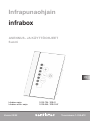
INSTRUCTIONS FOR INSTALLATION AND USE
English
SV
FI
RU
ET
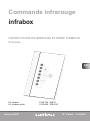
Infrared control unit
infrabox
Infrabox Set 1-035-704 / IRB-S
Infrabox white Set 1-039-846 / IRB-S-W

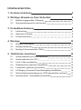
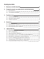
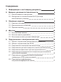
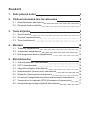
Table of Contents
1. About this instruction manual 4
2. Important information for your safety 5
2.1. Intended use 5
2.2. Safety information for the installer 7
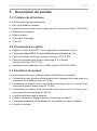
3. Product description 8
3.1. Scope of delivery 8
3.2. Optional accessories 8
3.3. Product functions 8
4. Installation 10
4.1. Installing the power supply unit 10
4.2. Installing the control unit 11
4.3. Installing the foil temperature sensor 13
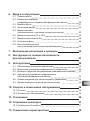
5. Electrical connection 14
5.1. Connection area for sensor/control unit 14
5.2. Connection diagram for 230 V 15
5.3. Connecting the light / fan 16
5.4. Connecting the seat sensor (optional) 16
5.5. Connecting the foil sensor (optional) 16
5.6. Connecting the HV input (remote start/enable input) 16
5.7. Connecting the safety temperature limiter (optional) 17
5.8. Connecting the infrared heater / infrared plate 17

EN
6. Starting up 18
6.1. Operating mode 19
6.2. Operating type (infrared heater/infrared plate) 20
6.3. Operating time 21
6.4. Foil sensor 22
6.5. Seat time (optional for seat sensor) 23
6.6. On-time (I/0 and I/0/I) 24
6.7. Out-time (I/0/I) 26
6.8. Leading/trailing edge phase control 29
6.9. HV input (remote start/enable input) 29
7. Performing tests 30
8. Safety information for the user 31
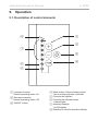
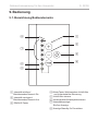
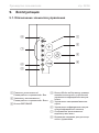
9. Operation 32
9.1. Description of control elements 32
9.2. Switching the infrared controller 33
9.3. Activating the dimming function for the light/fan 33
9.4. Dimming function for infrared heater/infrared plate 34
9.5. Standby for remote operation 35
9.6. Seat sensor (optional) 35
10. Cleaning and maintenance 36
10.1. Cleaning 36
10.2. Maintenance 36
11. Disposal 36
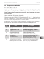
12. Troubleshooting 37
12.1. Error messages 37
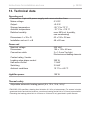
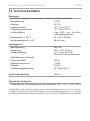
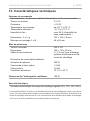
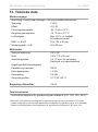
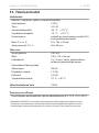
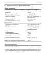
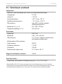
13. Technical data 38

Instructions for installation and use p. 4/38
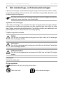
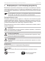
1. About this instruction manual
Read these installation and operating instructions carefully and keep them within
reach when using the infrared control unit. This ensures that you can refer to
information about your safety and the operation at any time.
Symbols used for warning notices
In these instructions for installation and use, a warning notice located next to
an activity indicates that this activity poses a risk. Always observe the warning
notices. This prevents damage to property and injuries, which in the worst case
may be fatal.
The warning notices contain keywords, which have the following meanings:
DANGER!
Serious or fatal injury will occur if this warning notice is not observed.
WARNING!
Serious or fatal injury can occur if this warning notice is not observed.
CAUTION!
Minor injuries can occur if this warning notice is not observed.
ATTENTION!
This keyword is a warning that damage to property can occur.
Other symbols
This symbol indicates tips and useful information.
Do not cover Read the operating instructions
These installation and operating instructions can also be found in the
downloads section of our website: www.sentiotec.com/downloads.

EN
Instructions for installation and use p. 5/38
2. Important information for your safety
The infrared controller has been produced in accordance with the
safety regulations applicable for technical units. However, hazards
may occur during use. Therefore adhere to the following safety
information and the specic warning notices in the individual chap-
ters. Also observe the safety information for the devices connected.
2.1. Intended use
The Infrabox infra controller is used exclusively for controlling and
operating the light/fan and infrared heater/infrared plate.
Observe the instructions for this in the operating instruction manual.
The infrared controller may only be used for controlling a maximum
capacity of 3.5 kW.
Overview of the operating modes:
Switchable: up to 3.5 kW
Half-wave control (dimmable): up to 1.3 kW
Leading edge phase control (dimmable): up to 350 W
The Infrabox infrared controller is only suitable for use
with intrinsically safe infrared heaters and infrared plates.
If no intrinsically safe products are being used, a safety
temperature limiter must be connected.

Instructions for installation and use p. 6/38
Suitable infrared heaters: DIR-350-R, WIR-350-R, DIR-500-R,
WIR-500-R, DIR-750-R, WIR-750-R, DIR-1300-R, WIR-1300-R,
ECO-350-R, ECO-350-G, ECO-500-R, ECO-500-G, ECO-750-R,
O-IRC-W
Suitable infrared plates: IR-WP-175, IR-WP-100, IR-WP-390,
IR-WP-510, IR-WPHL-510, IR-WPHL-100, IR-WPHL-390, IR-WPHL-175
ATTENTION!
Only use infrared plates in connection with the optional WC4-IRF-F
foil sensors.
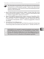
●Before using the controller for the rst time, check that the cabin
is ready to operate. Particularly if the controller is switched on
by remotely.
●Only the mains connection cable provided or the optional one
for Switzerland (IR-CP-CH) may be used.
●The power supply unit may only be installed and operated
together with the control unit provided.
Any use exceeding this scope is considered improper use. Improper
use can result in damage to the product, in severe injuries or death.

EN
Instructions for installation and use p. 7/38
2.2. Safety information for the installer
●The clamping connections may only be installed by a qualied
electrician or similarly qualied person.
●The plugs connectors may be installed by the user.
●Installation and connection of the infrared control unit may only
be performed when the power supply is disconnected.
●Also comply with the regulations applicable at the installation
location.
●Before the infrared controller is switched on, make sure that no
ammable objects have been hung over the infrared heater or
on the infrared plate.
●For your own safety, consult your supplier in the event of prob-
lems that are not described in sucient detail in the installation
and operating instructions.

Instructions for installation and use p. 8/38
3. Product description
3.1. Scope of delivery
●Infrabox controller
●Infrabox power supply unit
●Power supply unit connection cable 2.5 m (item no.: IR-CP-EH)
●Installation material
●Installation instruction manual
●Light plug
●HV plug
3.2. Optional accessories
●Foil sensor (WC4-IRF-F) incl. 5 m connection cable
●Seating sennsor (IRB-F-S) incl. 1 m connection cable
●Infrared heater plug (item no.: WC4-P-RA)
●Infrared mains connection cable 2.5 m, Switzerland (item no.: IR-CP-CH)
●Fan for IR cabins incl. cable and plug (WC4-IRX-FAN)
3.3. Product functions
The Infrabox infrared controller features the following functions:
●Switching the infrared heater or infrared plate with a heating capacity
of max. 3.5 kW
●Controlling (dim) the infrared controller in 5 levels with the half-wave
control unit (up to 1.3 kW)
●Controlling (dim) the infrared controller in 5 levels with the leading
edge phase control (up to 350 W)
●Remote start function
●Seating sensor function (optional accessories)
●Controlling (dim) the light or fan in 5 levels
●Timer function

EN
Instructions for installation and use p. 9/38
●If infrared heaters are connected, they must have a safety temperature limiter.
For suitable infrared heaters see 2.1. Intended use on page 5.
●If infrared plates are connected, the WC4-IRF-F foil sensors must be used
and activated (see 4.3. Installing the foil temperature sensor on page 13
and 5.5. Connecting the foil sensor (optional) on page 16). For suitable
infrared plates see 2.1. Intended use on page 5.
●Automatic heating period limiter
The infrared controller shuts down automatically after the maximum heat-
ing period for safety reasons (see also 6.3. Operating time on page 21).
The EN 60335-2-53 species a maximum heating period limit of 6 hours
for private infrared cabins. For infrared cabins in hotels, apartment blocks
and similar locations, a maximum heating period limit of 12 hours is
permissible. Extending the heating period limit to 18 hours or 24 hours
is only permitted in public infrared cabins.
!
The Infrabox infrared controller is suitable for use with intrinsically safe
infrared heaters and infrared plates. If no intrinsically safe products are
being used, a safety temperature limiter must be connected.

Installation instructions, for professionals only p. 10/38
4. Installation
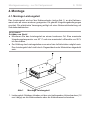
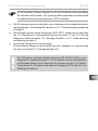
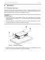
4.1. Installing the power supply unit
ATTENTION!
Damage to the unit
●Install the power supply unit in a dry place. Maintain a maximum ambient
temperature of 40 °C and a maximum humidity of 95%.
●A free circulation of air must be ensured to cool the power supply unit. The pow-
er supply unit must not be covered by any objects or materials.
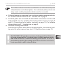
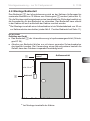
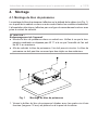
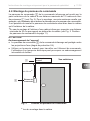
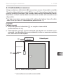
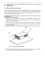
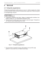
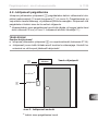
The power supply unit is installed on the cabin roof (Fig.1), on the cabin wall or in
another suitable location in accordance with the ambient conditions. The power
is supplied with a mains connection cable and safety plug.
1. Screw the Infrabox power supply unit housing to the cabin ceiling or the cabin
wall with the four wooden screws provided (16 mm long).
Fig. 1 Installing the power supply unit

EN
Installation instructions, for professionals only p. 11/38
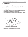
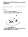
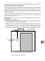
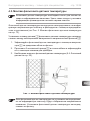
4.2. Installing the control unit
The control unit 2 of the infrared controller is installed on the outside wall of the
cabin with a maximum clearance of 10 metres from the power supply unit 1 (see
Fig. 2). For the installation, a standard jigsaw is required to cut out the recess for
the control unit. The control unit can be installed both inside and outside the cabin.
* For installing inside an infrared cabin, a minimum clearance of 30 cm
must be maintained (see Fig. 2 Control unit position on page 11).
ATTENTION!
Damage to the unit
●The control unit 2 of the infrared controller is splashproof (protection
class IP X4).
●Work on the control unit must only be carried out using a standard screwdriver.
Using a cordless screwdriver may cause irreparable damage to the housing.
Power unit
Infrabox External view
Control
unit
1
2
Fig. 2 Control unit position
* for assembly inside the cabin
min. 30 cm *

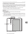
Installation instructions, for professionals only p. 12/38
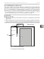
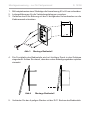
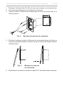
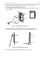
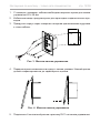
1. Cut out the 60 x 48 mm recess using a jigsaw, for example.
2. Provide cable guides for the connecting cables.
3. Screw the housing to the cabin wall through the hole with the 4 wood screws
enclosed.
4. The front panel of the control unit is inserted with slight pressure
into the housing. Ensure that the lower catch engage noticeably.
5. Connect the 4-pin connector with the RJ11 socket on the control unit.
Fig. 4 Installing the control unit
Fig. 3 Installing the control unit
60 mm
48 mm

EN
Installation instructions, for professionals only p. 13/38
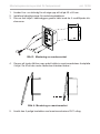
If the foil temperature sensor is not tted directly on the infrared plate,
it will produce incorrect measured values. Install the foil temperature
sensor directly on the foil.
The foil temperature sensor is only required for infrared plate heating sys-
tems. Observe the details of the plate heating system manufacturer here.
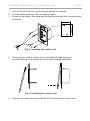
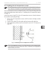
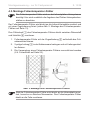
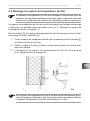
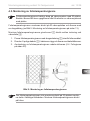
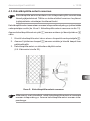
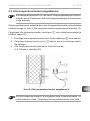
4.3. Installing the foil temperature sensor
The foil temperature sensor is installed directly on the infrared heating plate and
xed with a cable strain relief (seeFig. 5: Installing the foil temperature sensor
on page 13)
Install the sensor head 1 of the foil temperature sensor directly between
the insulation and heating foil 4.
1. Secure the foil temperature sensor with the strain relief 2 outside
the foil area.
2. Lay the 2-pin cable 3 in the cabin wall and secure with cable ties.
3. A foil temperature sensor must be activated to use it (6.4. Foil sensor on
page 22).
Fig. 5: Installing the foil temperature sensor

Installation instructions, for professionals only p. 14/38
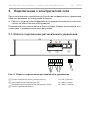
5. Electrical connection
Observe the following points when connecting the power to the infrared controller:
●Work on the infrared controller may only be performed when the power has
been disconnected.
All components on the Infrabox power supply unit are connected as shown in
the gures below:
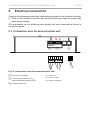
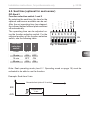
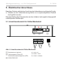
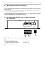
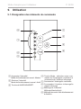
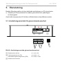
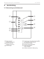
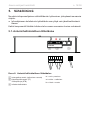
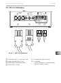
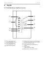
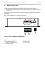
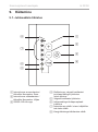
5.1. Connection area for sensor/control unit
Fig. 6: Connection area for sensor/control unit
1 2 3
1 Seat sensor (optional)
2 Foil temperature sensor (FF)
Safety temperature limiter (STB)
3 Infrabox control unit
rd = red = rot
wt = white = weiß
bk = black = schwarz
STB
Auto
FF
rd wt bk

EN
Installation instructions, for professionals only p. 15/38
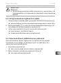
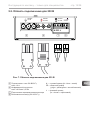
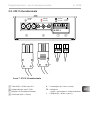
230V/50Hz
max.16A
230V/50Hz
max.3,5kW
230V/50Hz
max.100W
N PE L
230 VAC
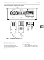
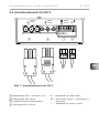
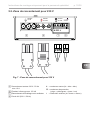
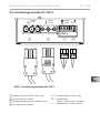
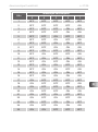
5.2. Connection diagram for 230 V
5 6 7 8
5 Mains connection cable
230 V / 50 Hz max. 16 A
6 Infrared heater max. 3.5 kW
7 Light connection or fan connection
8 HV input (230 V / 50 Hz)
Fig. 7: Connection area for 230 V
N = neutral line (bl = blue = blau)
PE = earth conductor
(ye/gn = yellow/green = gelb / grün)
L = outer conductor (br = brown = braun)

Installation instructions, for professionals only p. 16/38
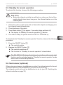
5.3. Connecting the light / fan
Clamp the light or fan to the 3-pin light/fan plug according to
Fig. 7: Connection area for 230 V on page 15.
5.4. Connecting the seat sensor (optional)
Clamp the seat sensor line to the 3-pin seat sensor plug according to
Fig. 6: Connection area for sensor/control unit on page 14. Observe
the instructions for this in the operating instruction manual.
5.5. Connecting the foil sensor (optional)
Clamp the foil sensor line on the 2-pin foil sensor plug to FF accord-
ing to Fig. 6: Connection area for sensor/control unit on page 14.
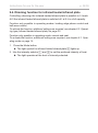
5.6. Connecting the HV input (remote start/enable input)
The input becomes active by applying alternating current
(230 V / 50 Hz) – depending on the remote start or enable input
setting. The input is connected using 2-pole HV plug according to
Fig. 7: Connection area for 230 V on page 15.
The EN 60335-2-53 states that the controller (in the remote start
setting) must be set to “Standby for remote operation” mode before
each remote start procedure.
Refer to chapter 6.9. HV input (remote start/enable input) on page
29 to follow the exact step-by-step procedure.
WARNING!
Personal injury
●The clamping connections may only be installed by a qualied electri-
cian or similarly qualied person.

EN
Installation instructions, for professionals only p. 17/38
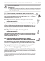
5.7. Connecting the safety temperature limiter
(optional)
When using infrared heaters and infrared plates without intrinsic safety,
a safety temperature limiter is required and must be connected!
The STB line is connected as shown in Fig. 6: Connection area for
sensor/control unit on page 14 to the STB connection.
5.8. Connecting the infrared heater / infrared plate
Connect the infrared heater/infrared plate to the connection provided
according to Fig. 7: Connection area for 230 V on page 15. Observe
the instructions for this in the operating instruction manual.

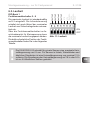
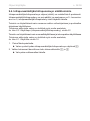
Installation instructions, for professionals only p. 18/38
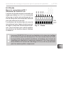
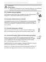
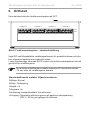
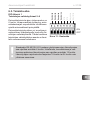
ON
OFF
DIP-Bank 4 DIP-Bank 3 DIP-Bank 2 DIP-Bank 1
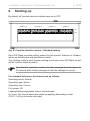
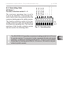
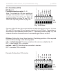
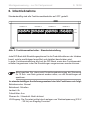
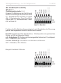
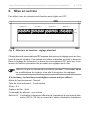
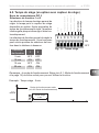
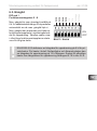
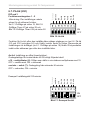
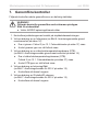
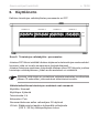
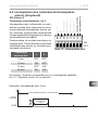
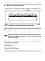
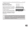
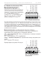
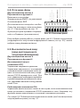
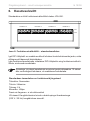
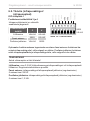
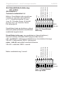
6. Starting up
By default, all function selection switches are set to OFF.
Each DIP Bank provides setting options for the product features of Infrabox,
which are listed below and described in detail.
The settings made in each function setting are shown in the DIP-Bank as well
as the function selection switch.
Fig. 8: Function selection switch – Standard setting
Note that the controller needs to be disconnected from the mains for
10 seconds after making changes so that the settings are saved.
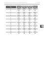
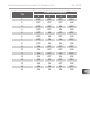
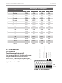
For standard deliveries, the features are as follows:
Operating mode: Normal
Operating type: Switch
Operating time: 6 hours
Foil sensor: O
Leading/trailing edge phase control: Not activated
HV input: The remote start takes place by applying alternating current
(230 V / 50 Hz) at remote start input.

EN
Installation instructions, for professionals only p. 19/38
Normal: Dimmable light / fan. Switchable or dimmable infrared heater/infra-
red plate.
Activating the dimming function of the infrared heater/infrared plate is done via
the infra-controller, see 6.2. Operating type (infrared heater/infrared plate) on
page 20.
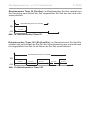
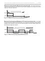
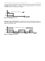
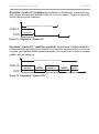
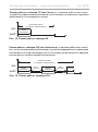
Timer I/0 (On/O): In the operating mode, On/O switches the controls o after
the set On-time has elapsed and is not activated again.
Dimmable light / fan. Switchable infrared heater / infrared plate.
For additional settings, see 6.6. On-time (I/0 and I/0/I) on page 24 and Fig.
18:
Timer I/0 operating mode on page 28.
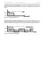
Timer I/0/1 (On/O/On): In the operating mode, On/O/On switches the infrared
controller o after the elapsed On-time and, after the set O-time, is activated
again for the duration of the On-time.
Dimmable light / fan. Switchable infrared heater / infrared plate.
For additional settings, see 6.6. On-time (I/0 and I/0/I) on page 24, 6.7. Out-
time (I/0/I) on page 26 and Fig. 18: Timer I/0 operating mode on page 28,
Fig. 19: Timer I/0/I operating mode on page 28.
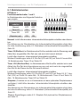
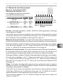
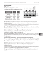
ON
OFF
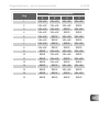
Operating mode
Operating time
Infra
Infra
Operating time
Operating time
Operating time
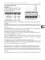
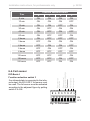
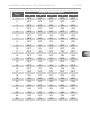
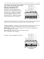
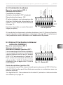
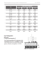
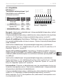
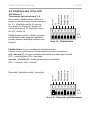
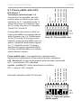
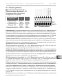
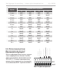
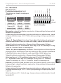
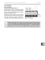
Fig. 9: Operating mode
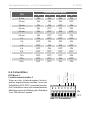
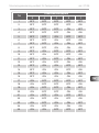
Operating mode
Function selec-
tion switch 1 2
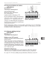
Normal OFF OFF
Timer I/0 ON OFF
Timer I/0/I OFF ON
Seat (optional) ON ON
6.1. Operating mode
DIP-Bank 1
Function selection switch 1 and 2
In the operating mode the following
settings are possible:
Seat (Function is only available in combination with the optional seat sensor):
Dimmable light / fan. Switchable or dimmable infrared heater/infrared plate.
Activating the dimming function of the infrared heater/infrared plate is done via
the infra-controller, see 6.2. Operating type (infrared heater/infrared plate) on
page 20.
For additional settings, see 6.5. Seat time (optional for seat sensor) on page 23.

Installation instructions, for professionals only p. 20/38
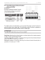
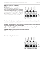
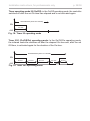
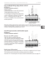
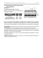
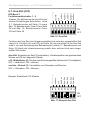
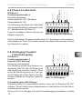
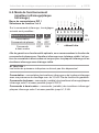
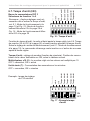
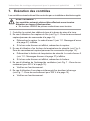
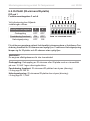
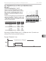
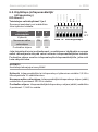
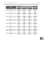
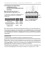
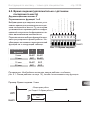
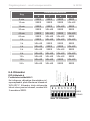
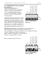
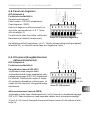
Fig. 10: Infrared operating type
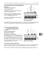
6.2. Operating type (infrared heater/
infrared plate)
DIP-Bank 1
Function selection switch 3 and 4
ON
OFF
Operating mode
Operating time
Infra
Infra
Operating time
Operating time
Operating time
Operating mode
The following settings are possible
for the infra-controller:
Function selection
switch 3 4
Switch OFF OFF
Leading edge phase
control
ON OFF
Half-wave control OFF ON
To enable optimum functionality, we recommend the phase control function for
infrared heaters with visible light. The half-wave control function is suitable for
infrared plates and infrared heaters without visible light.
ATTENTION!
The specied output limits may not be exceeded!
Switching: Switching the infrared heater or infrared plate with a heating capacity
of max. 3.5 kW. No dimming funcion.
Leading edge phase control: Controlling (dimming) the infrared heater/infrared
plate is possible in 5 levels up to 350 W.
Half-wave control: Controlling (dimming) the infrared heater/infrared plate is
possible in 5 levels up to 1.3 kW.
Sidan laddas...
Sidan laddas...
Sidan laddas...
Sidan laddas...
Sidan laddas...
Sidan laddas...
Sidan laddas...
Sidan laddas...
Sidan laddas...
Sidan laddas...
Sidan laddas...
Sidan laddas...
Sidan laddas...
Sidan laddas...
Sidan laddas...
Sidan laddas...
Sidan laddas...
Sidan laddas...
Sidan laddas...
Sidan laddas...
Sidan laddas...
Sidan laddas...
Sidan laddas...
Sidan laddas...
Sidan laddas...
Sidan laddas...
Sidan laddas...
Sidan laddas...
Sidan laddas...
Sidan laddas...
Sidan laddas...
Sidan laddas...
Sidan laddas...
Sidan laddas...
Sidan laddas...
Sidan laddas...
Sidan laddas...
Sidan laddas...
Sidan laddas...
Sidan laddas...
Sidan laddas...
Sidan laddas...
Sidan laddas...
Sidan laddas...
Sidan laddas...
Sidan laddas...
Sidan laddas...
Sidan laddas...
Sidan laddas...
Sidan laddas...
Sidan laddas...
Sidan laddas...
Sidan laddas...
Sidan laddas...
Sidan laddas...
Sidan laddas...
Sidan laddas...
Sidan laddas...
Sidan laddas...
Sidan laddas...
Sidan laddas...
Sidan laddas...
Sidan laddas...
Sidan laddas...
Sidan laddas...
Sidan laddas...
Sidan laddas...
Sidan laddas...
Sidan laddas...
Sidan laddas...
Sidan laddas...
Sidan laddas...
Sidan laddas...
Sidan laddas...
Sidan laddas...
Sidan laddas...
Sidan laddas...
Sidan laddas...
Sidan laddas...
Sidan laddas...
Sidan laddas...
Sidan laddas...
Sidan laddas...
Sidan laddas...
Sidan laddas...
Sidan laddas...
Sidan laddas...
Sidan laddas...
Sidan laddas...
Sidan laddas...
Sidan laddas...
Sidan laddas...
Sidan laddas...
Sidan laddas...
Sidan laddas...
Sidan laddas...
Sidan laddas...
Sidan laddas...
Sidan laddas...
Sidan laddas...
Sidan laddas...
Sidan laddas...
Sidan laddas...
Sidan laddas...
Sidan laddas...
Sidan laddas...
Sidan laddas...
Sidan laddas...
Sidan laddas...
Sidan laddas...
Sidan laddas...
Sidan laddas...
Sidan laddas...
Sidan laddas...
Sidan laddas...
Sidan laddas...
Sidan laddas...
Sidan laddas...
Sidan laddas...
Sidan laddas...
Sidan laddas...
Sidan laddas...
Sidan laddas...
Sidan laddas...
Sidan laddas...
Sidan laddas...
Sidan laddas...
Sidan laddas...
Sidan laddas...
Sidan laddas...
Sidan laddas...
Sidan laddas...
Sidan laddas...
Sidan laddas...
Sidan laddas...
Sidan laddas...
Sidan laddas...
Sidan laddas...
Sidan laddas...
Sidan laddas...
Sidan laddas...
Sidan laddas...
Sidan laddas...
Sidan laddas...
Sidan laddas...
Sidan laddas...
Sidan laddas...
Sidan laddas...
Sidan laddas...
Sidan laddas...
Sidan laddas...
Sidan laddas...
Sidan laddas...
Sidan laddas...
Sidan laddas...
Sidan laddas...
Sidan laddas...
Sidan laddas...
Sidan laddas...
Sidan laddas...
Sidan laddas...
Sidan laddas...
Sidan laddas...
Sidan laddas...
Sidan laddas...
Sidan laddas...
Sidan laddas...
Sidan laddas...
Sidan laddas...
Sidan laddas...
Sidan laddas...
Sidan laddas...
Sidan laddas...
Sidan laddas...
Sidan laddas...
Sidan laddas...
Sidan laddas...
Sidan laddas...
Sidan laddas...
Sidan laddas...
Sidan laddas...
Sidan laddas...
Sidan laddas...
Sidan laddas...
Sidan laddas...
Sidan laddas...
Sidan laddas...
Sidan laddas...
Sidan laddas...
Sidan laddas...
Sidan laddas...
Sidan laddas...
Sidan laddas...
Sidan laddas...
Sidan laddas...
Sidan laddas...
Sidan laddas...
Sidan laddas...
Sidan laddas...
Sidan laddas...
Sidan laddas...
Sidan laddas...
Sidan laddas...
Sidan laddas...
Sidan laddas...
Sidan laddas...
Sidan laddas...
Sidan laddas...
Sidan laddas...
Sidan laddas...
Sidan laddas...
Sidan laddas...
Sidan laddas...
Sidan laddas...
Sidan laddas...
Sidan laddas...
Sidan laddas...
Sidan laddas...
Sidan laddas...
Sidan laddas...
Sidan laddas...
Sidan laddas...
Sidan laddas...
Sidan laddas...
Sidan laddas...
Sidan laddas...
Sidan laddas...
Sidan laddas...
Sidan laddas...
Sidan laddas...
Sidan laddas...
Sidan laddas...
Sidan laddas...
Sidan laddas...
Sidan laddas...
Sidan laddas...
Sidan laddas...
Sidan laddas...
Sidan laddas...
Sidan laddas...
Sidan laddas...
Sidan laddas...
Sidan laddas...
Sidan laddas...
Sidan laddas...
Sidan laddas...
Sidan laddas...
Sidan laddas...
-
 1
1
-
 2
2
-
 3
3
-
 4
4
-
 5
5
-
 6
6
-
 7
7
-
 8
8
-
 9
9
-
 10
10
-
 11
11
-
 12
12
-
 13
13
-
 14
14
-
 15
15
-
 16
16
-
 17
17
-
 18
18
-
 19
19
-
 20
20
-
 21
21
-
 22
22
-
 23
23
-
 24
24
-
 25
25
-
 26
26
-
 27
27
-
 28
28
-
 29
29
-
 30
30
-
 31
31
-
 32
32
-
 33
33
-
 34
34
-
 35
35
-
 36
36
-
 37
37
-
 38
38
-
 39
39
-
 40
40
-
 41
41
-
 42
42
-
 43
43
-
 44
44
-
 45
45
-
 46
46
-
 47
47
-
 48
48
-
 49
49
-
 50
50
-
 51
51
-
 52
52
-
 53
53
-
 54
54
-
 55
55
-
 56
56
-
 57
57
-
 58
58
-
 59
59
-
 60
60
-
 61
61
-
 62
62
-
 63
63
-
 64
64
-
 65
65
-
 66
66
-
 67
67
-
 68
68
-
 69
69
-
 70
70
-
 71
71
-
 72
72
-
 73
73
-
 74
74
-
 75
75
-
 76
76
-
 77
77
-
 78
78
-
 79
79
-
 80
80
-
 81
81
-
 82
82
-
 83
83
-
 84
84
-
 85
85
-
 86
86
-
 87
87
-
 88
88
-
 89
89
-
 90
90
-
 91
91
-
 92
92
-
 93
93
-
 94
94
-
 95
95
-
 96
96
-
 97
97
-
 98
98
-
 99
99
-
 100
100
-
 101
101
-
 102
102
-
 103
103
-
 104
104
-
 105
105
-
 106
106
-
 107
107
-
 108
108
-
 109
109
-
 110
110
-
 111
111
-
 112
112
-
 113
113
-
 114
114
-
 115
115
-
 116
116
-
 117
117
-
 118
118
-
 119
119
-
 120
120
-
 121
121
-
 122
122
-
 123
123
-
 124
124
-
 125
125
-
 126
126
-
 127
127
-
 128
128
-
 129
129
-
 130
130
-
 131
131
-
 132
132
-
 133
133
-
 134
134
-
 135
135
-
 136
136
-
 137
137
-
 138
138
-
 139
139
-
 140
140
-
 141
141
-
 142
142
-
 143
143
-
 144
144
-
 145
145
-
 146
146
-
 147
147
-
 148
148
-
 149
149
-
 150
150
-
 151
151
-
 152
152
-
 153
153
-
 154
154
-
 155
155
-
 156
156
-
 157
157
-
 158
158
-
 159
159
-
 160
160
-
 161
161
-
 162
162
-
 163
163
-
 164
164
-
 165
165
-
 166
166
-
 167
167
-
 168
168
-
 169
169
-
 170
170
-
 171
171
-
 172
172
-
 173
173
-
 174
174
-
 175
175
-
 176
176
-
 177
177
-
 178
178
-
 179
179
-
 180
180
-
 181
181
-
 182
182
-
 183
183
-
 184
184
-
 185
185
-
 186
186
-
 187
187
-
 188
188
-
 189
189
-
 190
190
-
 191
191
-
 192
192
-
 193
193
-
 194
194
-
 195
195
-
 196
196
-
 197
197
-
 198
198
-
 199
199
-
 200
200
-
 201
201
-
 202
202
-
 203
203
-
 204
204
-
 205
205
-
 206
206
-
 207
207
-
 208
208
-
 209
209
-
 210
210
-
 211
211
-
 212
212
-
 213
213
-
 214
214
-
 215
215
-
 216
216
-
 217
217
-
 218
218
-
 219
219
-
 220
220
-
 221
221
-
 222
222
-
 223
223
-
 224
224
-
 225
225
-
 226
226
-
 227
227
-
 228
228
-
 229
229
-
 230
230
-
 231
231
-
 232
232
-
 233
233
-
 234
234
-
 235
235
-
 236
236
-
 237
237
-
 238
238
-
 239
239
-
 240
240
-
 241
241
-
 242
242
-
 243
243
-
 244
244
-
 245
245
-
 246
246
-
 247
247
-
 248
248
-
 249
249
-
 250
250
-
 251
251
-
 252
252
-
 253
253
-
 254
254
-
 255
255
-
 256
256
-
 257
257
-
 258
258
-
 259
259
-
 260
260
-
 261
261
-
 262
262
-
 263
263
-
 264
264
-
 265
265
-
 266
266
-
 267
267
-
 268
268


på andra språk
- eesti: Sentiotec infrabox Kasutusjuhend
- français: Sentiotec infrabox Manuel utilisateur
