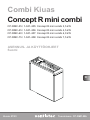
Sentiotec Concept R mini combi Användarmanual
- Typ
- Användarmanual

Version 07/23 Ident. no. CP-RMC-MA
INSTRUCTIONS FOR INSTALLATION AND USE
English
EN
DE
FR
SV
FI
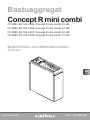
Sauna heater
Concept R mini combi
CP-RMC-35 / 1-041-405: Concept R mini combi 3.5 kW
CP-RMC-45 / 1-041-406: Concept R mini combi 4.5 kW
CP-RMC-60 / 1-041-407: Concept R mini combi 6.0 kW
CP-RMC-75 / 1-041-408: Concept R mini combi 7.5 kW

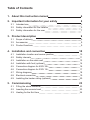
Table of Contents
1. About this instruction manual 4
2. Important information for your safety 5
2.1. Intended use 5
2.2. Safety information for the installer 5
2.3. Safety information for the user 7
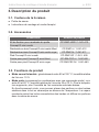
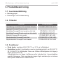
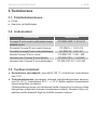
3. Product description 9
3.1. Scope of delivery 9
3.2. Accessories 9
3.3. Product functions 9
4. Installation and connection 10
4.1. Installation location and sensor position 10
4.2. Safety intervals 11
4.3. Installation on the cabin wall 12
4.4. Installation with foot (optional) 14
4.5. Connection diagram for 400V 3N~ 16
4.6. Connection diagram for 230V 1N~ 17
4.7. Wiring diagrams 18
4.8. Electrical connection 19
4.9. Installing the heater railing (optional) 20
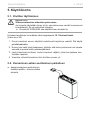
5. Commissioning 23
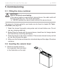
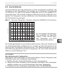
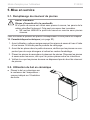
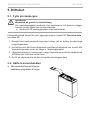
5.1. Filling the stone container 23
5.2. Inserting the ceramic bowl 23
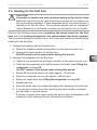
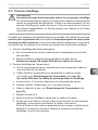
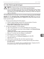
5.3. Heatingforthersttime 24

EN
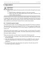
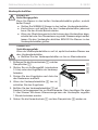
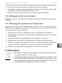
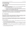
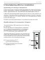
6. Operation 25
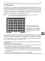
6.1. Finnish sauna mode 25
6.2. Combi mode 26
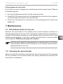
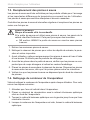
7. Maintenance 28
7.1. Extended periods of non-use 28
7.2. Cleaning the sauna heater 28
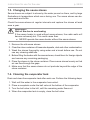
7.3. Changing the sauna stones 29
7.4. Cleaning the evaporator tank 29
7.5. Cleaning the ceramic bowl 30
7.6. Descaling the evaporator tank 30
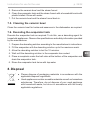
8. Disposal 30
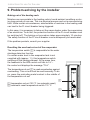
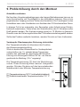
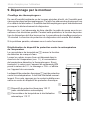
9. Problem-solving by the installer 31
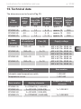
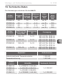
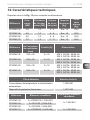
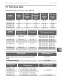
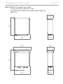
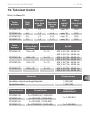
10. Technical data 32

Instructions for installation and use p. 4/32
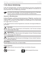
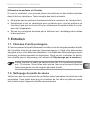
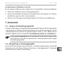
1. About this instruction manual
Carefully read these instructions for installation and use, and keep them near
the sauna. This ensures that you can refer to information about your safety and
the operation at any time.
Symbols used for warning notices
In these instructions for installation and use, a warning notice located next to
an activity indicates that this activity poses a risk. Always observe the warning
notices. This prevents damage to property and injuries, which in the worst case
may be fatal.
The warning notices contain keywords, which have the following meanings:
DANGER!
Serious or fatal injury will occur if this warning notice is not observed.
WARNING!
Serious or fatal injury can occur if this warning notice is not observed.
CAUTION!
Minor injuries can occur if this warning notice is not observed.
ATTENTION!
This keyword is a warning that damage to property can occur.
Other symbols
This symbol indicates tips and useful information.
Do not cover Read the operating instructions
These installation and operating instructions can also be found in the
downloads section of our website: www.sentiotec.com/downloads.

EN
Instructions for installation and use p. 5/32
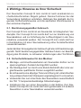
2. Important information for your safety
The Concept R mini combi sauna heater has been produced in ac-
cordance with the applicable safety rules and regulations. However,
hazards may occur during use. Therefore adhere to the following
safetyinformationandthespecicwarningnoticesintheindividual
chapters.
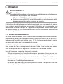
2.1. Intended use
The Concept R mini combi is a sauna heater with integrated evapora-
tor. The Concept R mini combi may only be used for heating sauna
cabins and for increasing the humidity inside the sauna cabin.
The Concept R mini combi must only be used in combination with
a sauna control unit that does not include remote start functions.
Any use exceeding this scope is considered improper use. Improper
use can result in damage to the product, severe injuries or death.
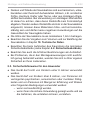
2.2. Safety information for the installer
●Installing and connecting the sauna heater may only be performed
when the power supply is disconnected.
●Installationmayonlybeperformedbyaqualiedelectricianor
similarlyqualiedperson.
●A fully disconnecting all-pole isolating device compliant with
overvoltagecategoryIIImustbettedonsite.
●Always use silicone cables that are heat-resistant up to 150 °C
to connect the sauna heater.
●Only install one sauna heater in the cabin. The Concept R mini
combi sauna heater must not be used together with other sauna
heaters in a sauna cabin.

Instructions for installation and use p. 6/32
●The roof and walls of the sauna cabin must be manufactured
from low-resin, untreated or thermally treated wood, e.g. Nordic
spruce,hemlock,pineorr,orfromlaminatedwoodenmateri-
als. If laminated wooden materials are used, make sure that the
adhesive used in them does not produce formaldehyde. If other
materials than wood are used in the sauna cabin, these materi-
als must be heat-resistant and corrosion-resistant and must not
causeanynegativeeectsonthehealthofthesaunausers.
●The height of the sauna cabin must be at least 1.64 m.
● Observethespecicationsonvolumesandonventilationofthe
sauna cabin in chapter 10. Technical data.
●When positioning the sauna heater, observe the minimum safety
distances (see chapter 4.2. Safety intervals).
●Also comply with the regulations applicable at the installation
location.
●For your own safety, consult your supplier in the event of prob-
lemsthatarenotexplainedinsucientdetailintheinstallation
instructions.
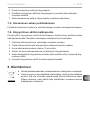
2.3. Safety information for the user
●The device must not be used by children under 8 years old.
●The device may only be used by children over 8 years old, by
persons with limited psychological, sensory or mental capabili-
ties or by persons with lack of experience/knowledge under the
following conditions:
– They are supervised.
– They have been shown how to use the device safely and
are aware of the hazards that could occur.

EN
Instructions for installation and use p. 7/32
●Children must not play with the device.
●Children under 14 years old may only clean the device if they
are supervised.
● Forhealthreasons,donotusethesaunawhenundertheinu-
ence of alcohol, medication or drugs.
●Never operate the sauna heater without sauna stones as this
cancauseres.
● Makesurethatnoammableobjectshavebeenplacedonthe
sauna heater before the sauna control unit is switched on.
●Heat up the sauna heater for half an hour BEFORE using the
saunaforthersttime.DoNOTremaininthesaunacabinduring
this period. Then ventilate the sauna cabin well (see 5.3. Heating
for the rst time on page 23).
●Never touch the sauna heater while it is operating. The surfaces
of the sauna heater and sauna stones become extremely hot.
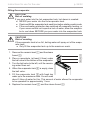
●NEVERpourwaterintothehotevaporatortank.Checkandll
the evaporator tank each time before starting combi mode. If the
overheatingprotectionhasswitchedoevaporatorheating,orif
your sauna control unit reports a lack of water, allow the evaporator
to cool down BEFORE you pour water into the evaporator tank.
●For your own safety, consult your supplier in the event of prob-
lemsthatarenotdescribedinsucientdetailintheoperating
instructions.

Instructions for installation and use p. 8/32
3. Product description
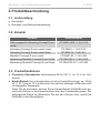
3.1. Scope of delivery
●Sauna heater
●Instructions for installation and use
3.2. Accessories
Accessories Item number
Set of brackets for the Concept R mini combi
heater railing
CP-RMC-HSR / 1-041-410
Wood railing for Concept R mini combi, lime wood CP-RMC-L / 1-041-412
Wood railing for Concept R mini combi, walnut CP-RMC-N / 1-041-411
Foot for Concept R mini combi CP-RMC-SF / 1-041- 409
Cover foot for Concept R mini, lime wood CP-RM-CSF-L / 1-041482
Cover foot for Concept R mini, walnut
CP-RM-CSF-N / 1-041-483
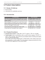
3.3. Product functions
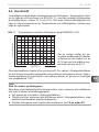
●Finnish sauna mode: usually 80 to 100 °C; approx. 10% rel. humidity
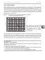
●Combi mode (only in combination with a combi control): approx. 40 to 65 °C,
35% to 70% humidity. The maximum permissible relative humidity decreases
with increasing temperature.
If you wish, you can put fragrances or dried herbs in the ceramic bowl over
the evaporator in combi mode. The rising steam releases essential oils from
theherbsandfragrancesllthesaunacabin.

EN
Installation instructions, for professionals only p. 9/32
WARNING!
Danger of electric shock
●The sauna heater may only be installed and connected when the power
supply is disconnected.
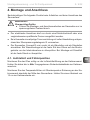
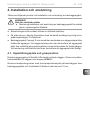
4. Installation and connection
Take the following points into account when positioning and connecting the sauna
heater:
●Theelectricalconnectionmayonlybeperformedbyaqualiedelectricianor
similarlyqualiedperson.
●A fully disconnecting all-pole isolating device compliant with overvoltage
categoryIIImustbettedonsite.
●The Concept R mini combi sauna heater can be used as a wall-mounted
heater or as a free-standing heater. When mounted to the wall, check that
theheaterhasbeenrmlyinstalledonthemountingrailbeforestartingheater
operation.Wheninstallingthedevicewithfoot,checkthatthefootingisrm.
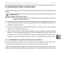
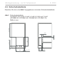
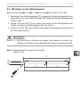
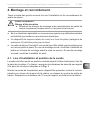
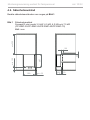
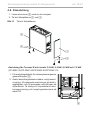
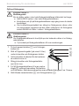
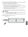
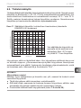
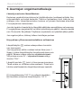
4.1. Installation location and sensor position
Position the heater centrally in front of the air intake opening on the cabin wall.
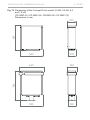
ComplywiththesafetyintervalstothecabinwallspeciedinFig. 1.
Install the temperature sensor with overheat cut-out to the cabin wall above the
centre of the sauna heater. Maintain a distance of 15 cm to the sauna cabin roof.

min 50
580
min 130 min 900
687
220 50
100
20
Installation instructions, for professionals only p. 10/32
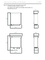
Fig. 1 Safety intervals
for the Concept R mini combi 3.5 kW, 4.5 kW, 6.0 kW and 7.5 kW
(CP-RMC-35 / CP-RMC-45 / CR-RMC-60 / CP-RMC-75)
Dimensions in mm
4.2. Safety intervals
ObservetheminimumsafetyintervalsspeciedinFig. 1.

EN
Installation instructions, for professionals only p. 11/32
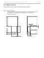
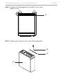
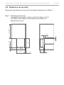
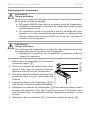
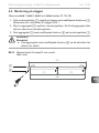
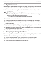
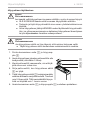
4.3. Installation on the cabin wall
Observe Fig. 1, Fig. 2, Fig. 3 and Fig. 4 (page 11, 12, 13).
1. Attach the mounting rail 1 to the wall horizontally using the wood screws
supplied 2. Observe the minimum intervals for the heater shown in Fig. 1.
2. Suspend the heater 3 from the mounting rail from above, moving it down-
wards.Makesurethattheheaterisushwiththewall.
3. Secure the heater 3 using the lock screws supplied 4 on the mounting
rail 1.
Fig. 2 Position of the mounting rail for Concept R mini combi
Dimensions in mm
2
WARNING!
Risk of re
●Toxtheheaterinplaceandsecureitagainstslippage,usethe
supplied lock screw 4 for attachment.
1
170 170
360
340

Installation instructions, for professionals only p. 12/32
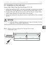
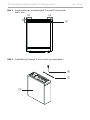
63
110 110
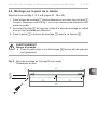
Fig. 3 Position of the mounting rail for Concept R mini combi
Dimensions in mm
Fig. 4 Securing the Concept R mini combi (mounting rail)
1
3
4
1
63
110 110

EN
Installation instructions, for professionals only p. 13/32
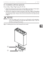
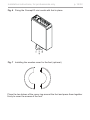
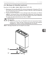
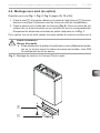
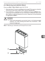
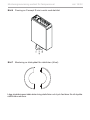
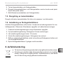
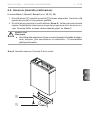
4.4. Installation with foot (optional)
Observe Fig. 1, Fig. 5, Fig. 6 (page 10, 13, 14).
1. Attach the foot 1 using the screws enclosed 2 to the bottom of the heater.
Please note that the round recess is on the evaporator side.
2. Axthefootusingthescrewsenclosedtotheoor(Fig. 6). Depending
ontheoorconditions,usetheenclosedwoodscrewsoranchorswiththe
corresponding screws. Observe the minimum intervals for the heater shown
in Fig. 1.
WARNING!
Risk of re
●Affix the heater with the foot on a sufficiently solid substrate,
e.g. on the substrate onto which the sauna cabin is built – NOT on
theoorcoveringofthesauna.
Fig. 5 Installing the foot on the Concept R mini combi
2
1

Installation instructions, for professionals only p. 14/32
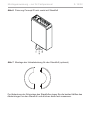
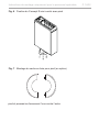
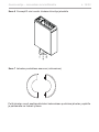
Fig. 6 Fixing the Concept R mini combi with foot in place
Fig. 7 Installing the wooden cover for the foot (optional)
Place the two halves of the cover ring around the foot and press them together
rmlytocoverthescrewsofthefoot.

L1 L2 N
L3 U
V
N
Wr
r
w
w
ϑϑ
U
V
NW
W
400V 3N~
NVNU
PE
N
N
V1
Wm
N
U1
WM
L2
L1
L3
4EN
Installation instructions, for professionals only p. 15/32
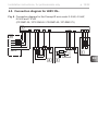
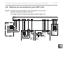
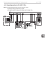
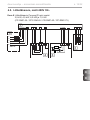
4.5. Connection diagram for 400V 3N~
Fig. 8
2
3
5
1
Connection diagram for the Concept R mini combi 3.5 kW, 4.5 kW,
6.0 kW and 7.5 kW
(CP-RMC-35 / CPC-RM-45 / CR-RMC-60 / CP-RMC-75)

Installation instructions, for professionals only p. 16/32
L1 L2 N
L3 U
V
N
Wr
r
w
w
ϑϑ
U
V
NW
W
230V 1N~
NVNU
L
PE
N
N
V1
Wm
N
U1
WM
4
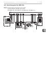
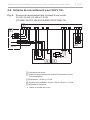
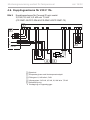
4.6. Connection diagram for 230V 1N~
Fig. 9
2
3
5
1
Connection diagram for the Concept R mini combi 3.5 kW, 4.5 kW,
6.0 kW and 7.5 kW
(CP-RMC-35 / CPC-RM-45 / CR-RMC-60 / CP-RMC-75)
1 Sauna control unit
2 Temperature sensor with excess temperature cut-out
3 Evaporator 1.0 kW or 1.5 kW
4 Heating system 3.45 kW, 4.5 kW, 6.0 kW or 7.5 kW
5 Power supply
Remove the copper bridge
*
*

EN
Installation instructions, for professionals only p. 17/32
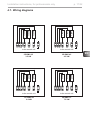
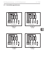
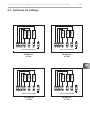
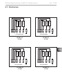
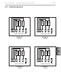
CP-RMC-35
3.5 kW
U V W N
1,15kW
1,15kW
1,15kW
N N
W V U
CP-RMC-60
6.0 kW
4.7. Wiring diagrams
CP-RMC-45
4.5 kW
U V W N
1,5kW
1,5kW
1,5kW
N N
W V U
U V W N
2,0kW
2,0kW
2,0kW
N N
W V U
to the control unit
to the control unit
to the control unit
U V W N
2,5kW
2,5kW
2,5kW
N N
W V U
to the control unit
CP-RMC-75
7.5 kW

U
V
W
N
PE
N
N
Installation instructions, for professionals only p. 18/32
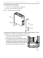
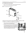
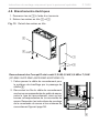
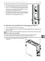
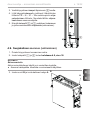
4.8. Electrical connection
1. Unscrew the screws 3 with a screwdriver.
2. Remove the cover plates 1 and 2.
2
3
1
3
Connecting the Concept R mini combi 3.5 kW, 4.5 kW, 6.0 kW and 7.5 kW
(CP-RMC-35 / CP-RMC-45 / CR-RMC-60 / CP-RMC-75)
1. Guide the connection cable for the heating sys-
tem through the feed-through 4.
2. Connect the wires of the connection cable to
the matching terminals of the sauna heater,
depending on the type of connection, and to
the matching control device terminals. Observe
the installation instructions for the sauna control
and the connection diagrams on page 16.
Fig. 10 Removing the cover plates
4

EN
Installation instructions, for professionals only p. 19/32
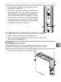
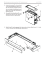
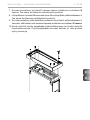
3. Guide the evaporator cable through the feed-
through 5.
4. Connect the wires of the evaporator cable to the
PE – N – U1 – Wm terminals on the connector
block and to the matching sauna control unit
terminals. Observe the installation instructions
for the sauna control unit when doing so.
5. Re-attach the cover plates 1 and 2 to the
sauna heater or proceed with the installation of
the heater railing (optional).
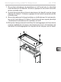
ATTENTION!
Damage to the product
The product can be damaged by use of a cordless drill.
●Use a normal screwdriver to install the railing bracket.
A
B
B
5
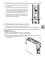
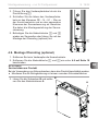
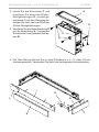
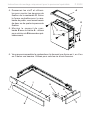
4.9. Installing the heater railing (optional)
1. Remove the ceramic bowl from the evaporator.
2. Remove the cover plates 1 and 2 as described in 4.9 on page 18.
3. Unscrew the screws B and remove
cover frame A.

Installation instructions, for professionals only p. 20/32
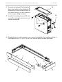
4. Unscrew the screws C and install with
them the angle railing brackets D.
Depending on the preferred form of
the heater railing, you will need two
or four angle railing brackets.
5. Install the railing bracket E with
cover A using the previously re-
moved screws B.
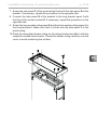
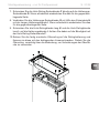
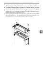
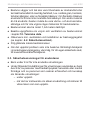
6. Depending on requirements, you can put together the heater railing in
the shape of an L, U or O. To do this, use the wood screws provided.
C
A
D
F
H
G
I
K
L
E
B
Sidan laddas...
Sidan laddas...
Sidan laddas...
Sidan laddas...
Sidan laddas...
Sidan laddas...
Sidan laddas...
Sidan laddas...
Sidan laddas...
Sidan laddas...
Sidan laddas...
Sidan laddas...
Sidan laddas...
Sidan laddas...
Sidan laddas...
Sidan laddas...
Sidan laddas...
Sidan laddas...
Sidan laddas...
Sidan laddas...
Sidan laddas...
Sidan laddas...
Sidan laddas...
Sidan laddas...
Sidan laddas...
Sidan laddas...
Sidan laddas...
Sidan laddas...
Sidan laddas...
Sidan laddas...
Sidan laddas...
Sidan laddas...
Sidan laddas...
Sidan laddas...
Sidan laddas...
Sidan laddas...
Sidan laddas...
Sidan laddas...
Sidan laddas...
Sidan laddas...
Sidan laddas...
Sidan laddas...
Sidan laddas...
Sidan laddas...
Sidan laddas...
Sidan laddas...
Sidan laddas...
Sidan laddas...
Sidan laddas...
Sidan laddas...
Sidan laddas...
Sidan laddas...
Sidan laddas...
Sidan laddas...
Sidan laddas...
Sidan laddas...
Sidan laddas...
Sidan laddas...
Sidan laddas...
Sidan laddas...
Sidan laddas...
Sidan laddas...
Sidan laddas...
Sidan laddas...
Sidan laddas...
Sidan laddas...
Sidan laddas...
Sidan laddas...
Sidan laddas...
Sidan laddas...
Sidan laddas...
Sidan laddas...
Sidan laddas...
Sidan laddas...
Sidan laddas...
Sidan laddas...
Sidan laddas...
Sidan laddas...
Sidan laddas...
Sidan laddas...
Sidan laddas...
Sidan laddas...
Sidan laddas...
Sidan laddas...
Sidan laddas...
Sidan laddas...
Sidan laddas...
Sidan laddas...
Sidan laddas...
Sidan laddas...
Sidan laddas...
Sidan laddas...
Sidan laddas...
Sidan laddas...
Sidan laddas...
Sidan laddas...
Sidan laddas...
Sidan laddas...
Sidan laddas...
Sidan laddas...
Sidan laddas...
Sidan laddas...
Sidan laddas...
Sidan laddas...
Sidan laddas...
Sidan laddas...
Sidan laddas...
Sidan laddas...
Sidan laddas...
Sidan laddas...
Sidan laddas...
Sidan laddas...
Sidan laddas...
Sidan laddas...
Sidan laddas...
Sidan laddas...
Sidan laddas...
Sidan laddas...
Sidan laddas...
Sidan laddas...
Sidan laddas...
Sidan laddas...
Sidan laddas...
Sidan laddas...
Sidan laddas...
Sidan laddas...
Sidan laddas...
Sidan laddas...
Sidan laddas...
Sidan laddas...
Sidan laddas...
Sidan laddas...
Sidan laddas...
Sidan laddas...
Sidan laddas...
Sidan laddas...
Sidan laddas...
Sidan laddas...
Sidan laddas...
Sidan laddas...
Sidan laddas...
Sidan laddas...
Sidan laddas...
Sidan laddas...
-
 1
1
-
 2
2
-
 3
3
-
 4
4
-
 5
5
-
 6
6
-
 7
7
-
 8
8
-
 9
9
-
 10
10
-
 11
11
-
 12
12
-
 13
13
-
 14
14
-
 15
15
-
 16
16
-
 17
17
-
 18
18
-
 19
19
-
 20
20
-
 21
21
-
 22
22
-
 23
23
-
 24
24
-
 25
25
-
 26
26
-
 27
27
-
 28
28
-
 29
29
-
 30
30
-
 31
31
-
 32
32
-
 33
33
-
 34
34
-
 35
35
-
 36
36
-
 37
37
-
 38
38
-
 39
39
-
 40
40
-
 41
41
-
 42
42
-
 43
43
-
 44
44
-
 45
45
-
 46
46
-
 47
47
-
 48
48
-
 49
49
-
 50
50
-
 51
51
-
 52
52
-
 53
53
-
 54
54
-
 55
55
-
 56
56
-
 57
57
-
 58
58
-
 59
59
-
 60
60
-
 61
61
-
 62
62
-
 63
63
-
 64
64
-
 65
65
-
 66
66
-
 67
67
-
 68
68
-
 69
69
-
 70
70
-
 71
71
-
 72
72
-
 73
73
-
 74
74
-
 75
75
-
 76
76
-
 77
77
-
 78
78
-
 79
79
-
 80
80
-
 81
81
-
 82
82
-
 83
83
-
 84
84
-
 85
85
-
 86
86
-
 87
87
-
 88
88
-
 89
89
-
 90
90
-
 91
91
-
 92
92
-
 93
93
-
 94
94
-
 95
95
-
 96
96
-
 97
97
-
 98
98
-
 99
99
-
 100
100
-
 101
101
-
 102
102
-
 103
103
-
 104
104
-
 105
105
-
 106
106
-
 107
107
-
 108
108
-
 109
109
-
 110
110
-
 111
111
-
 112
112
-
 113
113
-
 114
114
-
 115
115
-
 116
116
-
 117
117
-
 118
118
-
 119
119
-
 120
120
-
 121
121
-
 122
122
-
 123
123
-
 124
124
-
 125
125
-
 126
126
-
 127
127
-
 128
128
-
 129
129
-
 130
130
-
 131
131
-
 132
132
-
 133
133
-
 134
134
-
 135
135
-
 136
136
-
 137
137
-
 138
138
-
 139
139
-
 140
140
-
 141
141
-
 142
142
-
 143
143
-
 144
144
-
 145
145
-
 146
146
-
 147
147
-
 148
148
-
 149
149
-
 150
150
-
 151
151
-
 152
152
-
 153
153
-
 154
154
-
 155
155
-
 156
156
-
 157
157
-
 158
158
-
 159
159
-
 160
160
-
 161
161
-
 162
162
-
 163
163
-
 164
164


Sentiotec Concept R mini combi Användarmanual
- Typ
- Användarmanual
på andra språk
Relaterade papper
-
Sentiotec CP-RM-35 Concept R Mini Sauna Heater Användarmanual
-
-
Sentiotec Concept R combi Användarmanual
-
-
-
-
-
-
HARVIA QUBE-360 Användarmanual
-
