
3000113-2010-12-13
EXHAUSTO CDT A/S
C.F. Tietgens Boulevard 41
DK-5220 Odense SØ
Tel. +45 7010 2234
Fax +45 7010 2235
www.exhausto-cdt.dk
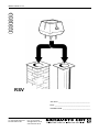
RSV
Job name: __________________________________
Fitter: ______________________________________
Installation date: ______________________________
DK
SE
NO
DE
GB
NL
FR

3000113-2010-12-13
2 / 52
1. GB - Product information .................................................................................................3
1.1 Construction and design........................................................................................3
1.2 Installation instructions .........................................................................................4
1.3 Wiring .......................................................................................................................8
1.4 Service and cleaning ..............................................................................................9
1.5 Technical specications .........................................................................................9
1.6 Warranty ..................................................................................................................9
2. DE - Produktinformation ................................................................................................10
2.1 Produktbeschreibung ...........................................................................................10
2.2 Mechanische Montage..........................................................................................11
2.3 Elektrischer Anschluß ..........................................................................................15
2.4 Wartung und Reinigung .......................................................................................16
2.5 Technische Daten .................................................................................................16
2.6 Garantie .................................................................................................................16
3. DK - Produktinformation ................................................................................................17
3.1 Konstruktion og design ........................................................................................17
3.2 Mekanisk installation ............................................................................................18
3.3 El-tilslutning ..........................................................................................................22
3.4 Service og rengøring ............................................................................................23
3.5 Tekniske data ........................................................................................................23
3.6 Garanti ...................................................................................................................23
4. NO - Produktinformasjon ...............................................................................................24
4.1 Konstruksjon .........................................................................................................24
4.2 Mekanisk installasjon ...........................................................................................25
4.3 Elektrisk tilkobling ................................................................................................28
4.4 Service og rengjøring ...........................................................................................29
4.5 Tekniske data ........................................................................................................29
4.6 Garanti ...................................................................................................................29
5. SE - Produktbeskrivning ................................................................................................30
5.1 Konstruktion..........................................................................................................30
5.2 Mekanisk installation ............................................................................................31
5.3 El-anslutning .........................................................................................................35
5.4 Service och rengöring ..........................................................................................36
5.5 Tekniska data ........................................................................................................36
5.6 Service ...................................................................................................................36
6. FR - Description du produit ..........................................................................................37
6.1 Construction..........................................................................................................37
6.2 Installation mécanique .........................................................................................38
6.3 Branchement électrique .......................................................................................42
6.4 Entretien et nettoyage ..........................................................................................43
6.5 Spécications techniques....................................................................................43
6.6 Garantie .................................................................................................................43
7. NL - Product beschrijving ..............................................................................................44
7.1 Constructie en ontwerp ........................................................................................44
7.2 Montagehandleiding .............................................................................................45
7.3 Elektrische aansluiting. ........................................................................................49
7.4 Service en Onderhoud..........................................................................................50
7.5 Technische specicatie ........................................................................................50
7.6 Garantie .................................................................................................................50
EU declaration of conformity ...............................................................................................51

3000113-2010-12-13
3 / 52
GB
1. GB - Product information
The EXHAUSTO CDT RSV type chimney fan is supplied with location brackets, armoured
cable, safety wire and a mineral wool mat, as well as packing to ensure the fan does not
vibrate. (Two wing screws are also included, to be used where conditions allow).
Bad lighting habits can result in problems with soot, chimney res, etc. which might damage
the chimney fan. Please see our advice about lighting and maintaining a re at www.
exhausto-cdt.com or www.exhausto.co.uk.
Warning!
• All installations must be carried out by competent personnel in
accordance with national laws and regulations
• Avoid chimney res - ensure that the chimney has been swept before
mounting the fan
• The chimney fan should always be switched on when the replace or
boiler is in use
• Please always read the installation instructions for the EXHAUSTO CDT
control unit, before installation of the chimney fan.
• If the EXHAUSTO CDT fan system has been designed for solid fuel/multi
fuel installations then please ensure the design meets the requirements
of BS EN15287-1. If this can not be achieved, then a smoke alarm must be
installed in the same room as the appliance.
• EXHAUSTO CDT would always recommend the use of a smoke alarm
when a solid fuel open re is installed
• Avoid build up of soot and tar use only well seasoned wood (moisture
content max 20%)
• Fans serving biomass boilers will inevitably receive a deposit from the
appliance. Especially on biomass Boilers IT IS ESSENTIAL THAT A RE-
GULAR INSPECTION AND CLEANING REGIME IS IMPLEMENTED, ESPE-
CIALLY IN THE EARLY DAYS OF USAGE, TO ESTABLISH A PATTERN FOR
TIMING OF REGULAR INSPECTIONS AND CLEANING.
1.1 Construction and design
The casing is manufactured in cast aluminium, the RSV fan is designed for vertical di-
scharge. It is available in ten sizes: the RSV 9, 12, 14, 16, 160, 200, 250, 315, 400 and 450.
The axial vanes on the RSV 9 – 16 are made of stainless steel; the centrifugal impeller on
the RSV 160 – 450 is cast in aluminium. Both types can be opened for service and mainte-
nance.
Weight:
Fan type Weight Fan type Weight
RSV009-4-1
RSV012-4-1
13 kg
17 kg
RSV160-4-1
RSV200-4-1
RSV250-4-1
RSV315-4-1
RSV400-4-1
14 kg
18 kg
27 kg
37 kg
47 kg
RSV014-4-1
RSV016-4-1
24 kg
33 kg
RSV400-4-2
RSV450-4-2
58 kg
67 kg
!

3000113-2010-12-13
4 / 52
GB
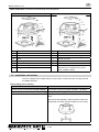
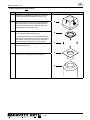
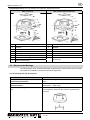
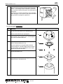
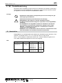
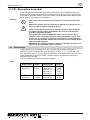
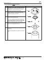
Main components: The RSV has the following main components
RSV 9-12-14-16 RSV 160-200-250-315-400-450
m
m
m
m
a Top section g Safety mesh
b Bottom section h Handle
c Motor i Armoured cable and connecting cable
d1 Vane j Mineral wool mat
d2 Centrifugal impeller k Safety wire
e1 Inlet for axial vane l Location bracket, bolt and nuts
e2 Inlet for centrifugal impeller m Screws to fasten top and bottom section
(Alternatively use supplied wing screw,
where conditions allow)
f Hinge
1.2 Installation instructions
The fan is designed to be tted directly on top of brick or steel chimneys, as long as these
are stable and level.
Before tting onto a chimney
If.... then..
the fan is to be mounted onto a brick chimney the chimney must have location brackets - see below
the fan is to be mounted onto a steel chimney a ange is required (supplied as an extra) - see below
the fan is a RSV 315, 400 or 450 the impeller is secured with a safety bracket for transpor-
tation.
Remove the transportation safety bracket located near
the impeller and check that the impeller can turn freely.

3000113-2010-12-13
5 / 52
GB
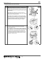
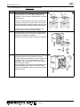
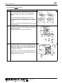
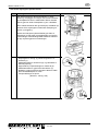
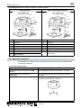
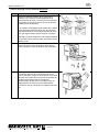
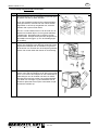
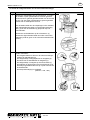
Before tting onto the brickwork of a chimney
Step Action
1 Measure the inside diameter of the chimney and cut the
size of the hole in the mineral wool mat accordingly
Note, however, that there must always be a minimum of
20 mm of mat surface at any point around the circumfe-
rence of the hole.
If a temperature sensor is to be installed with the chim-
ney, cut the aluminium foil on the mineral wool mat to
make room for the sensor; this also ensures that the
mat sits level on the chimney.
NB: The side of the mineral wool mat covered in alumi-
nium foil is to be placed uppermost, i.e. facing the fan.
2 Fit the location brackets in the grooves on the undersi-
de of the bottom section and fasten using the nuts and
bolts supplied.
Note that the bolts are to be inserted from beneath the
brackets.
3 Adjust the distance between the location brackets to t
the inside diameter of the chimney, and then tighten the
nuts. Note that there should be a 2-4 mm gap between
the brackets and the chimney so as to avoid transmit-
ting vibrations from the fan to the chimney.
A and B measurements: please refer to step 1.
The chimney fan can now be tted into place. Place the
mineral wool mat on top of the chimney, with the alumi-
nium foil side up, and place the fan on top.

3000113-2010-12-13
6 / 52
GB
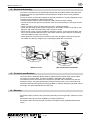
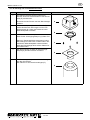
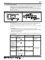
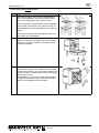
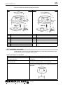
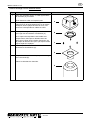
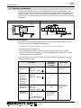
Before tting onto a steel chimney
Step Action
1 A ange (D) (supplied as extra) is used, tted so
that the spigot end sits inside the chimney (E).
A
B
C
D
E
2 Place the mineral wool mat (B) on the ange (D)
with the aluminium foil facing upwards and cut a
hole in the mineral wool mat, the hole being the
same diameter as the ange hole.
3 Cut the corners of the mineral wool mat, so there is
room to t the vibration dampers (C).
If a temperature sensor is to be installed with the
chimney fan, cut the aluminium foil on the mineral
wool mat to make room for the sensor; this also
ensures that the mat sits level on the chimney.
4 Fit the ange to the chimney fan, with the use of the
vibration dampers (C).
5 The fan can now be tted onto the chimney.

3000113-2010-12-13
7 / 52
GB
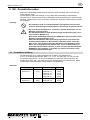
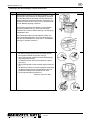
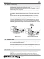
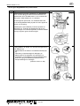
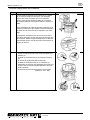
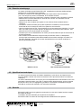
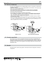
Fitting the chimney fan onto the chimney
Step Action
1 Attach the safety wire to the chimney (1). Use the screw
and rawl plug provided in the brickwork of the chimney or
the self-cutting screw if working on a steel chimney. Then
t the wire through the hole in the bottom section and into
the wire clamp.
Gently tighten the safety wire, and crimp (2) the wire
clamp so that the fan is held safely in place when opened
for servicing or cleaning purposes.
The isolation switch (supplied as extra) should be tted
onto the side of the chimney (3), so it is easily accessible
when servicing the fan. The armoured cable with connec-
ting cable should be mounted into the underside of the
isolator and up into the switch through the coupling.
2 Prior to use check that:
• The fan is closed and the fastening screws/wing
screws tightened (4)
• The safety wire is taut and the wire clamp crimped (5)
• The coupling nut on the armoured cable is tightened (6)
• The safety wire is securely attached to the chimney (7)
• That the user is aware that the fan must always be
switched on whenever the replace or boiler is in use
• The transportation safety bracket has been removed
(RSV315, -400 and -450).

3000113-2010-12-13
8 / 52
GB
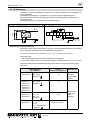
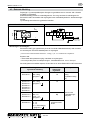
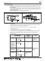
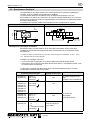
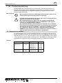
1.3 Wiring
Fan and motor specications are provided on the fan’s type plate. All the single-phased mo-
dels are adjustable.
Wires are to be connected as per the wiring diagram. For further details, please see guide-
lines for the EXHAUSTO CDT control units. All EXHAUSTO CDT fans require extra safe-
guards in accordance with power current regulations.
Any lightning conductor connected to the fan must respect current applicable legislation.
EXHAUSTO CDT Motor Grundfos Motor
Nreg
L
Z2 U1 T2
Z1 U2 T1
MAIN
AUX
No.: 3000194
N
R
D
1
0
1
6
0
Project:
Material:
Date:
Rev.:
Title:
Rev. No.: Ref.:
Format: A3
Weight:
Approved:
Draw. No.:
* Control measurement
Replaces:
Grundfos motor
Connection diagram
23-11-2009
100236
PMN
Unless otherwise specified tolerances are after
96780829
22-12-2009
A
Varenumre
EXHAUSTO GRUNDFOS FAN
1250431 87104366 RSV009-41
RSV160-41
1250433 87104367 RS012-41
1250102 87104368 RSV012-41
RS255-41
RSV200-41
8
7 6
5 4
3
2
1
AUX
MAIN
L1
N
POWER SUPPLY
1 x 230V ~ 50Hz
3 x 0,75
YEGN
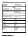
Isolation switch:
In accordance with the provisions of the EU Machinery Directive* a combustion-gas fan
must always have an isolation switch tted. The isolation switch must comply with national
wiring standards.
*Please refer to Machine Directive (2006/42/EF/-EEC/-EWG/-CEE) - Appendix 1item 1.6.3 “Separation of the sour-
ces of energy
The isolation switch must be ordered separately, as it is not part of the standard EXHAUSTO
CDT chimney fan delivery.
Connecting cable
and wiring
Variable adjust-
able electronic
regulator
Protection
RSV009-4-1
RSV160-4-1
brown = L
blue = Nreg.
yellow/green =
Yes
The motor can be
blocked.
(impedance-pro-
tected)
RSV012-4-1
RSV014-4-1
RSV016-4-1
RSV200-4-1
RSV250-4-1
RSV315-4-1
RSV400-4-1
brown = L
blue = Nreg.
yellow/green =
Yes
The motor requires
overload
protection
RSV250-4-3
RSV315-4-3
RSV400-4-3
brown = L1
blue = L2
black = L3
yellow/green =
No
RSV400-4-2
RSV450-4-2
1 - L1
2 - L2
3 - L3
4 + 5 Thermocal switch
yellow/green=
Yes, by frequency
converter max.
60Hz

3000113-2010-12-13
9 / 52
GB
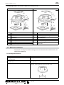
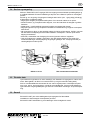
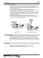
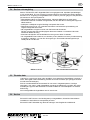
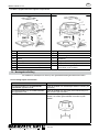
1.4 Service and cleaning
The motor in the RSV fan has special ball bearings that are sealed, lifetime lubricated, and
maintenance-free. Any replacement of these bearings should be carried out by qualied
professionals.
The fan should be checked and cleaned as required (at least once a year), depending on the
fuel being used. Respect the following procedure:
• Use the isolation switch to switch off the fan. Wait until the fan stops rotating
• Loosen the screw and open the top section of the fan so that it hangs on its hinges and the
safety wire
• Using a scraper or brush, carefully clean the vane / centrifugal impeller
• Check the path taken by the smoke through the top and bottom sections of the fan for soot
deposits, and clean where necessary with a scraper or brush
• When the fan is open it is also possible to sweep the chimney. In the case of the RSV 160-
450 it is recommended that the insert in the bottom section be removed prior to sweeping.
This allows better access to the chimney
• Check that there is free access for fresh air to the motor through the holes in the top sec-
tion. Make sure that any weights on the centrifugal impeller are not removed.
RSV 9-12-14-16 RSV 160-200-250-315-400-450
1.5 Technical specications
The sound level is below 68 dB at a distance greater than ve metres away from the RSV
fan when it is correctly tted. Further information is available in the catalogue.
The standard version of the RSV fan is designed to operate with a maximum ue gas tem-
perature of 250°C. At higher temperatures, though maximum 300°C, the mineral wool mat
should be replaced with adjusting screws (type RSD) or vibration dampers (type SVD.-RS) at
the ange. See special guidelines for these parts.
1.6 Warranty
EXHAUSTO CDT provides a two-year factory warranty on its ue gas fans, valid from invoice
date.
EXHAUSTO CDT fans must be installed by competent personnel.
EXHAUSTO CDT reserves the right to introduce changes to these guidelines without prior
notice.

3000113-2010-12-13
10 / 52
DE
2. DE - Produktinformation
Bitte immer die Montage Anleitung der EXHAUSTO CDT Automatik, bevor Montage des
Rauchsaugers, lesen.
Der EXHAUSTO CDT Rauchsauger vom Typ RSV wird serienmäßig mit Winkeleisen,
Panzerschlauch, Sicherungsseil sowie Isolierplatte aus Mineralwolle zwecks vibrationsfreier
Montage. Flügelschrauben sind auch dabei, und können verwendet werden falls die Umstän-
de es erlaubt..
Achtung!
• Die Installation muß von Fachhandwerkern durchgeführt und nach den
örtlichen Bestimmungen und gesetzlichen Vorschriften ausgeführt werden
• Um einen Schornsteinbrand zu vermeiden, muß der Schornstein vor der
Montage gereinigt werden
• Zur Kühlung des Motors muß der Rauchsauger bei Benutzung der Feuer-
stelle immer in Betrieb sein!
• Bitte immer die Montage Anleitung der EXHAUSTO CDT Automatik, bevor
Montage des Rauchsaugers, lesen
• Sofern das EXHAUSTO CDT Rauchsauger-System für Feuerstellen mit
Festbrennstoffen/mehreren Brennstoffen entwickelt wurde, stellen Sie
bitte sicher, dass die Vorrichtung die Standards nach EN15287-1 erfüllt.
Wenn dies nicht gewährleistet werden kann, muss ein Rauchmelder in
demselben Raum installiert werden, in dem sich auch das Gerät bendet.
• EXHAUSTO CDT empehlt, in der Nähe von offenen Feuerstellen stets
einen Rauchmelder anzubringen.
2.1 Produktbeschreibung
Der Rauchsauger ist ein vertikal ausblasender Ventilator aus Gußaluminium.
Er ist in 10 Ausführungen lieferbar: RSV 9, 12, 14, 16, 160, 200, 250, 315, 400 und 450.
Die Ausführungen RSV 9 - 16 sind mit Axialügel aus rostfreiem Stahl ausgerüstet, die
Ausführungen RSV 160 - 450 verfügen über ein Zentrifugalrad aus Gußaluminium. Beide
Ausführungen sind aufklappbar zwecks Wartung und Reinigung.
Gewichte:
Rauchsauger Gewicht Rauchsauger Gewicht
RSV009-4-1
RSV012-4-1
13 kg
17 kg
RSV160-4-1
RSV200-4-1
RSV250-4-1
RSV315-4-1
RSV400-4-1
14 kg
18 kg
27 kg
37 kg
47 kg
RSV014-4-1
RSV016-4-1
24 kg
33 kg
RSV400-4-2
RSV450-4-2
58 kg
67 kg
!

3000113-2010-12-13
11 / 52
DE
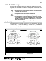
Hauptkomponenten: Der RSV besteht aus folgenden Hauptkomponenten:
RSV 9-12-14-16 RSV 160-200-250-315-400-450
m
m
m
m
a Oberteil g Abdeckgitter
b Unterteil h Handgriff
c Motor i Panzerschlauch und Anschlußkabel
d1 Axialügel j Mineralwollplatte
d2 Zentrifugalrad k Sicherungsseil
e1 Einlaßteil für Axialügel l Winkeleisen, Schrauben und Muttern
e2 Einlaßteil für Zentrifugalrad m Schrauben oder Flügelschrauben zum
abschliessen
f Sicherungsbeschlag
2.2 Mechanische Montage
Der Rauchsauger ist für die direkte Montage auf gemauerten Schornsteinen sowie für Stahl-
schornsteine mit stabilem und ebenem Abschluß vorgesehen.
Vor der Montage auf dem Schornstein
Bei... dann...
Montage des Rauchsaugers auf einem
gemauerten Schornstein…
sind am Rauchsauger Winkeleisen zu montieren – siehe
unten.
Montage des Rauchsaugers auf einem
Stahlschornstein…
ist der Rauchsauger mit einem Flansch (Sonderzubehör)
auszurüsten – siehe unten.
Rauchsauger vom Typ RSV 315, 400 oder
450...
ist die Transportsicherung am Laufrad zu entfernen und
zu kontrollieren, dass sich das Laufrad ungehindert dre-
hen kann.

3000113-2010-12-13
12 / 52
DE
Vor der Montage auf einem gemauerten Schornstein
Schritt Vorgehen
1 Die lichte Weite des Schornsteins messen und ein
entsprechendes Loch in der Mineralwollplatte aus-
schneiden. Jedoch müssen mindestens 20 mm Rand
stehen bleiben.
Wenn ein Temperaturfühler zusammen mit dem Rau-
chsauger montiert wird, ist dafür Platz in der Alufolie
der Mineralwollplatte auszuschneiden, damit der Rau-
chsauger eben auf der Platte montiert werden kann.
Hinweis: Die Alu-Folie der Mineralwollplatte muß
nach oben gegen den Rauchsauger zeigen.
2 Die Winkeleisen in den Nuten an der Unterseite des
Unterteils montieren und mit Hilfe der mitgelieferten
Schrauben und Muttern befestigen.
Hinweis: Die Schrauben sind von unten zu montieren.
3 Den Abstand zwischen den Winkeleisen der Schorn-
steinweite anpassen und die Muttern anziehen.
Hinweis: Zwischen Winkeleisen und Schornstein muß
ein Abstand von 2 - 4 mm vorhanden sein, damit
Vibrationen vom Rauchsauger nicht auf den Schorn-
stein übertragen werden.
Der Rauchsauger ist jetzt bereit für die Montage. Die
Mineralwollplatte jetzt mit der Alu-Folie nach oben
auf den Schornsteinkopf legen und den Rauchsauger
darauf montieren

3000113-2010-12-13
13 / 52
DE
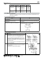
Vor der Montage auf einem Stahlschornstein:
Schritt Vorgehen
1 Für Stahlschornsteine wird ein Flansch (D)
benutzt, der durch Hineinschieben in den Schorn-
stein (E) montiert wird.
Zunächst wird der Flansch auf dem Rauchsauger
montiert:
A
B
C
D
E
2 Die Mineralwollplatte (B) auf den Flansch (D)
mit der Alufolie nach oben legen und ein Loch
entsprechend der Lichte des Flansches in der
Mineralwollplatte schneiden.
3 Die Ecken der Mineralwollplatte abschneiden,
damit für die Schwingungsdämper (C) Platz wird.
Wenn ein Temperaturfühler zusammen mit dem
Rauchsauger montiert wird, ist dafür Platz in der
Alufolie der Mineralwollplatte auszuschneiden,
damit der Rauchsauger eben auf der Platte mon-
tiert werden kann.
4 Den Rauchsauger mit Hilfe der Schwingungs-
dämpfer(C) auf dem Flansch montieren.
5 Der Rauchsauger ist jetzt bereit für die Montage
auf dem Schornstein.
Den Flansch im Schornstein anbringen (E).

3000113-2010-12-13
14 / 52
DE
Befestigen des Rauchsaugers auf dem Schornstein
Schritt Vorgehen
1 Das Sicherungsseil am Schornstein montieren (1). Bei
gemauerten Schornsteinen die mitgelieferte Schraube
und den Mauerdübel verwenden und bei Stahlschorn-
steinen selbstschneidende Schrauben verwenden. An-
schließend das Seil durch das Loch im Unterteil führen
und im Befestigungsring montieren.
Das Sicherungsseil leicht anziehen und den Befesti-
gungsring festklemmen (2), damit der Rauchgas-
ventilator beim Öffnen zwecks Wartung und Reinigung
festgehalten wird.
Den Wartungsschalter (Sonderzubehör) seitlich am
Schornsteinkopf befestigen (3). Den Panzerschlauch
mit dem Anschlußkabel von unten durch die Kabelein-
führung im Schalter montieren.
2 Vor Inbetriebnahme kontrollieren, daß:
• der Rauchsauger geschlossen ist und die Schrau-
ben/Flügelschrauben angezogen sind (4),
• das Sicherungsseil gespannt und der Befestigungs-
ring festgeklemmt ist (5),
• die Überwurfmutter des Panzerschlauchs angezo-
gen ist (6),
• das Sicherungsseil am Schornstein angeschraubt ist
(7),
• der Benutzer darüber in Kenntnis gesetzt wurde, daß
der Rauchsauger während der Benutzung der Feu-
erstelle/des Kessels stets in Betrieb sein muß,
• die Transportsicherung entfernt ist.
(RSV315,-400 und -450)

3000113-2010-12-13
15 / 52
DE
2.3 Elektrischer Anschluß
Die technischen Daten des Rauchsaugers und des Motors gehen aus den jeweils montierten
Typenschildern hervor. Sämtliche 1-phasigen Modelle sind regelbar.
Der elektrische Anschluß erfolgt gemäß Schaltplan. Ferner wird auf die Anleitung der jewei-
ligen EXHAUSTO CDT-Automatik verwiesen. Sämtliche Rauchsaugeren sind gegen direkte
Berührung zu schützen.
Eine Blitzableitung ist entsprechend den örtlichen gesetzlichen Vorschriften auszuführen.
EXHAUSTO CDT Motor Grundfos Motor
Nreg
L
Z2 U1 T2
Z1 U2 T1
MAIN
AUX
No.: 3000194
N
R
D
1
0
1
6
0
Project:
Material:
Date:
Rev.:
Title:
Rev. No.: Ref.:
Format: A3
Weight:
Approved:
Draw. No.:
* Control measurement
Replaces:
Grundfos motor
Connection diagram
23-11-2009
100236
PMN
Unless otherwise specified tolerances are after
96780829
22-12-2009
A
Varenumre
EXHAUSTO GRUNDFOS FAN
1250431 87104366 RSV009-41
RSV160-41
1250433 87104367 RS012-41
1250102 87104368 RSV012-41
RS255-41
RSV200-41
8
7 6
5 4
3
2
1
AUX
MAIN
L1
N
POWER SUPPLY
1 x 230V ~ 50Hz
3 x 0,75
YEGN
Montage von Wartungs-schaltern:
Die EXHAUSTO CDT weist darauf hin, daß die Richtlinie Maschinen *) die Montage eines
Wartungsschalters bei der festen Installation von Rauchsaugeren vorschreibt.
*) Es wird auf die “Richtlinie Maschinen 2006/42/EWG” - Anhang 1 - Nummer 1.6.3 ”Trennung von den Energiequel-
len” verwiesen”.
Der Schalter muß:
• abschließbar sein oder ist sichtbar in der Nähe des Rauchsaugers anzuordnen,
• in der Lage sein, sämtliche Pole von der Versorgungsspannung zu unterbrechen - Kontak-
tabstand mind. 3 mm bei jedem Pol.
• Maximale Vorsicherung 10Amp.
Der Wartungsschalter ist gesondert zu bestellen, da er nicht von der EXHAUSTO CDT-Lie-
ferung umfasst ist.
Anschlußkabel und elektrische
Schaltung
Stufenlos
elektronisch regelbar
Überlastschutz
RSV009-4-1
RSV160-4-1
braun = L
blau = Nreg
gelb/grün =
Ja
Der Motor verträgt
Blockierung
(impedanzge-
schützt)
RSV012-4-1
RSV014-4-1
RSV016-4-1
RSV200-4-1
RSV250-4-1
RSV315-4-1
RSV400-4-1
braun = L
blau = Nreg
gelb/grün =
Ja
Überlastschutz des
Motors erforderlich
RSV250-4-3
RSV315-4-3
RSV400-4-3
braun = L1
blau = L2
schwarz = L3
gelb/grün =
Nein
RSV400-4-2
RSV450-4-2
1 - L1
2 - L2
3 - L3
4 + 5 Termosicherung
- gelb/grün=
Ja, mit Frequenz-
umformer max. 60Hz

3000113-2010-12-13
16 / 52
DE
2.4 Wartung und Reinigung
Der Motor des EXHAUSTO CDT Rauchsaugers RSV ist mit geschlossenen, wartungs-freien
Spezialkugellagern ausgerüstet. Ein eventueller Austausch der Lager darf nur von Personen
mit entsprechenden Fachkennt-nissen vorgenommen werden.
Kontrolle und eventuelle Reinigung des Rauchsaugers ist mind. 1 Mal jährlich (je nach Art
des Brennstoffs) wie folgt vorzunehmen:
• Den Rauchsauger am Wartungsschalter abschalten; warten bis der Ventilator völlig still
steht.
• Die Schrauben lösen und das Oberteil nach hinten aufklappen, wo es vom Sicherungsbe-
schlag und vom Sicherungsseil festgehalten wird.
• Den Axialügel / das Zentrifugalrad vorsichtig mit einem Spachtel oder einer Bürste reini-
gen.
• Den Rauchweg durch Ober- und Unterteil auf Rußbildung kontrollieren und mit einem
Spachtel oder einer Bürste reinigen.
• Während der Rauchsauger geöffnet ist, ist gleichzeitig Zugang zum Reinigen des Schorn-
steins. Bei RSV 160-450 ist es zweckdienlich, das Einlaßteil im Unterteil zu demontieren.
Dadurch wird der Zugang zum Schornstein besser.
• Überprüfen, daß die Kühlluft durch die Löcher im Oberteil freien Zugang zum Motor hat.
• Vibrationen im Rauchsauger können von einer Unwucht aufgrund eines ver-schmutzten
Axialügels / Zentrifugalrades herrühren, und die Reinigung ist zu wieder-holen. Eventuelle
Auswuchtungsgewichte am Zentrifugalrad dürfen nicht entfernt werden.
RSV 9-12-14-16 RSV 160-200-250-315-400-450
2.5 Technische Daten
Der an die Umgebung abgegebene Schallpegel liegt bei einem Abstand zum Rauchsauger
von mehr als 5 Metern unter 68 dB(A). Dies gilt bei korrekt montiertem RSV. (Im übrigen
wird auf die Daten im Prospekt verwiesen.)
Der RSV ist in Standardausführung für eine maximale Rauchgastemperatur von 250°C kon-
struiert. Bei höheren Temperaturen, max. 300°C, ist der Rauchsauger statt der Mineralwoll-
platte mit Einstellschrauben vom Typ RSD oder Schwingungsdämpfern vom Typ SVD-RS in
Verbindung mit einem Flansch auszurüsten. Siehe gesonderte Anleitung.
2.6 Garantie
EXHAUSTO CDT leistet eine 2 jährige Werksgarantie auf den Rauchsauger, ab Rech-
nungsdatum.
Die Montage ist von Personen mit entsprechenden Fachkenntnissen auszuführen.
EXHAUSTO CDT behält sich das Recht auf Änderungen ohne vorherige Ankündigung vor.

3000113-2010-12-13
17 / 52
DK
3. DK - Produktinformation
EXHAUSTO CDT røgsuger type RSV leveres standard med vinkelben, panserslange, sik-
kerhedswire samt mineraluldsplade som pakning for vibrationsfri drift. (Desuden er vedlagt
vingeskruer, der kan monteres, hvis forholdene tillader det.)
Dårlige fyringsvaner kan resultere i problemer med sod, skorstensbrand, m.m. som kan
skade røgsugeren. Se vores råd om at fyre rigtigt på www.exhausto-cdt.dk.
Advarsel!
• Installationen skal udføres af kompetent personale i overensstemmelse
med gældende love og regler
• Undgå skorstensbrand - Fej skorstenen inden montage
• Røgsugeren skal altid være i drift ved anvendelse af ildstedet
• Læs altid installationsvejledningen for automatikken, før røgsugeren
installeres
• Er EXHAUSTO CDT røgsugeren en del af brændefyrede installationer skal
det sikres at kravene i EN15287-1 er overholdt. Hvis dette ikke kan opnås
skal der monteres en røgalarm i samme rum som brændselsenheden
• EXHAUSTO CDT vil altid anbefale opsætning af en røgalarm når en
brændefyret pejs er i brug.
3.1 Konstruktion og design
Røgsugeren er en ventilator konstrueret til vertikalt afkast og udført i støbt aluminium. Den
leveres i ti størrelser: RSV 9, 12, 14, 16, 160, 200, 250, 315, 400 og 450.
RSV 9 - 16 har aksialvinge af rustfrit stål og RSV 160 - 450 har centrifugalhjul i støbt alumi-
nium. Begge udførelser er oplukkelige for service og rengøring.
Vægt:
Røgsuger Vægt Røgsuger Vægt
RSV009-4-1
RSV012-4-1
13 kg
17 kg
RSV160-4-1
RSV200-4-1
RSV250-4-1
RSV315-4-1
RSV400-4-1
14 kg
18 kg
27 kg
37 kg
47 kg
RSV014-4-1
RSV016-4-1
24 kg
33 kg
RSV400-4-2
RSV450-4-2
58 kg
67 kg
!

3000113-2010-12-13
18 / 52
DK
Hovedkomponenter: RSV består af følgende hovedkomponenter:
RSV 9-12-14-16 RSV 160-200-250-315-400-450
m
m
m
m
a Toppart g Net
b Bundpart h Håndtag
c Motor i Panserslange og tilslutningskabel
d1 Aksialvinge j Mineraluldsplade
d2 Centrifugalhjul k Sikkerhedswire
e1 Aksialindsats l Vinkelben, bolte og møtrikker
e2 Centrifugalindsats m Skruer eller vingeskruer til at lukke røgsu-
geren med.
f Sikringsbeslag
3.2 Mekanisk installation
Røgsugeren er beregnet til direkte montage på murede skorstene samt stålskorstene med
stabil og plan afslutning.
Før montage på skorstenen
Hvis... så
røgsugeren skal monteres på en
muret skorsten...
skal røgsugeren forsynes med vinkelben - se nedenfor
røgsugeren skal monteres på en
stålskorsten...
skal røgsugeren forsynes med en ange (ekstra tilbehør)
- se nedenfor
røgsugeren er en RSV 315, 400 eller 450... skal transportsikringen ved løbehjulet fjernes, og det kon-
trolleres, at løbehjulet kan løbe uhindret rundt.

3000113-2010-12-13
19 / 52
DK
Før montage på muret skorsten
Trin Handling
1 Skorstenens lysning måles, og der laves et tilsvarende
hul i mineraluldspladen. Hullet må dog aldrig gøres
større, end at der er minimum 20 mm anlægsade
tilbage.
Hvis en temperaturføler installeres sammen med
røgsugeren, skal der skæres plads til den i alufolien på
mineraluldsmåtten for at røgsugeren kan stå plant på
måtten.
Bemærk: Alu-folien på mineraluldspladen skal vende op
mod røgsugeren.
2 Vinkelbenene monteres i sporene på undersiden af
bærepladen og fastgøres ved hjælp af de medleverede
bolte og møtrikker.
Bemærk, at boltene skal monteres nedefra.
3 Afstanden mellem vinkelbenene justeres i henhold til
skorstenens lysning, og møtrikkerne fastspændes. Be-
mærk, at der skal være 2 - 4 mm luft imellem vinkelben
og skorsten, således at der ikke overføres vibrationer
fra røgsuger til skorsten.
Røgsugeren er nu klar til montage. Mineraluldspladen
lægges på toppen af skorstenen med alufolien opad, og
røgsugeren placeres ovenpå.

3000113-2010-12-13
20 / 52
DK
Før montage på en stålskorsten:
Trin Handling
1 Til stålskorstene anvendes en ange (D), der mon-
teres ved at studsen sættes ned i skorstenen (E).
Først monteres angen på røgsugeren:
A
B
C
D
E
2 Placer mineraluldsmåtten (B) på angen (D) med
alufolien (C) opad og skær hul i mineraluldsmåtten
svarende til angens lysning
3 Skær hjørnerne af mineraluldsmåtten, så der bliver
plads til svingningsdæmperne (C)
Hvis en temperaturføler installeres sammen med
røgsugeren, skal der skæres plads til den i alufolien
på mineraluldsmåtten for at røgsugeren kan stå
plant på måtten.
4 Monter røgsugeren på angen ved hjælp af sving-
ningsdæmperne
5 Røgsugeren er nu klar til montage på skorstenen.
Placer angen i skorstenen.
Sidan laddas...
Sidan laddas...
Sidan laddas...
Sidan laddas...
Sidan laddas...
Sidan laddas...
Sidan laddas...
Sidan laddas...
Sidan laddas...
Sidan laddas...
Sidan laddas...
Sidan laddas...
Sidan laddas...
Sidan laddas...
Sidan laddas...
Sidan laddas...
Sidan laddas...
Sidan laddas...
Sidan laddas...
Sidan laddas...
Sidan laddas...
Sidan laddas...
Sidan laddas...
Sidan laddas...
Sidan laddas...
Sidan laddas...
Sidan laddas...
Sidan laddas...
Sidan laddas...
Sidan laddas...
Sidan laddas...
Sidan laddas...
-
 1
1
-
 2
2
-
 3
3
-
 4
4
-
 5
5
-
 6
6
-
 7
7
-
 8
8
-
 9
9
-
 10
10
-
 11
11
-
 12
12
-
 13
13
-
 14
14
-
 15
15
-
 16
16
-
 17
17
-
 18
18
-
 19
19
-
 20
20
-
 21
21
-
 22
22
-
 23
23
-
 24
24
-
 25
25
-
 26
26
-
 27
27
-
 28
28
-
 29
29
-
 30
30
-
 31
31
-
 32
32
-
 33
33
-
 34
34
-
 35
35
-
 36
36
-
 37
37
-
 38
38
-
 39
39
-
 40
40
-
 41
41
-
 42
42
-
 43
43
-
 44
44
-
 45
45
-
 46
46
-
 47
47
-
 48
48
-
 49
49
-
 50
50
-
 51
51
-
 52
52


på andra språk
- Deutsch: EXHAUSTO RSV Bedienungsanleitung
- français: EXHAUSTO RSV Le manuel du propriétaire
- English: EXHAUSTO RSV Owner's manual
- dansk: EXHAUSTO RSV Brugervejledning
- Nederlands: EXHAUSTO RSV de handleiding
Relaterade papper
Andra dokument
-
Exodraft RS Bruksanvisning
-
-
-
Exodraft EW41 Quick Start
-
-
-
-
-
-