
UK
NO
SE
RSG/RSGC
UK Read and save these instructions!
NO Lese og lagre disse instruksjonene!
SE Läs och spara dessa instruktioner!

1. UK – Product information . . . . . . . . . . . . . . . . . . . . . . . . . . . . . . . . . . . . . . . . . . . . 3
1.1 System description . . . . . . . . . . . . . . . . . . . . . . . . . . . . . . . . . . . . . . . . . . . . . . . . . . . . . . 3
1.2 Construction and design . . . . . . . . . . . . . . . . . . . . . . . . . . . . . . . . . . . . . . . . . . . . . . . . . . 3
1.3 Mechanical assembly. . . . . . . . . . . . . . . . . . . . . . . . . . . . . . . . . . . . . . . . . . . . . . . . . . . . . 6
1.3.1 Location of the fan ...........................................................................6
1.3.2 Installation of the silencer ....................................................................6
1.3.3 Installation of the fan.........................................................................7
1.4 Wiring . . . . . . . . . . . . . . . . . . . . . . . . . . . . . . . . . . . . . . . . . . . . . . . . . . . . . . . . . . . . . . 9
1.5 Spillage test and adjustment of the pressure dierential switch. . . . . . . . . . . . . . . . . . . . . . . . . 10
1.6 Maintenance . . . . . . . . . . . . . . . . . . . . . . . . . . . . . . . . . . . . . . . . . . . . . . . . . . . . . . . . . 11
1.7 Warranty. . . . . . . . . . . . . . . . . . . . . . . . . . . . . . . . . . . . . . . . . . . . . . . . . . . . . . . . . . . . 11
2. NO – Produkt informasjon . . . . . . . . . . . . . . . . . . . . . . . . . . . . . . . . . . . . . . . . . . . 12
2.1 Beskrivelse . . . . . . . . . . . . . . . . . . . . . . . . . . . . . . . . . . . . . . . . . . . . . . . . . . . . . . . . . . 12
2.2 Konstruksjon . . . . . . . . . . . . . . . . . . . . . . . . . . . . . . . . . . . . . . . . . . . . . . . . . . . . . . . . . 12
2.3 Montering. . . . . . . . . . . . . . . . . . . . . . . . . . . . . . . . . . . . . . . . . . . . . . . . . . . . . . . . . . . 15
2.3.1 Plassering...................................................................................15
2.3.2 Installasjon av lyddemperen.................................................................15
2.3.3 Installasjon av røyksugeren..................................................................16
2.4 Elektrisk tilkobling . . . . . . . . . . . . . . . . . . . . . . . . . . . . . . . . . . . . . . . . . . . . . . . . . . . . . 18
2.5 Lekkasjetest og justering av pressostaten. . . . . . . . . . . . . . . . . . . . . . . . . . . . . . . . . . . . . . . 19
2.6 Vedlikehold . . . . . . . . . . . . . . . . . . . . . . . . . . . . . . . . . . . . . . . . . . . . . . . . . . . . . . . . . . 20
2.7 Garanti . . . . . . . . . . . . . . . . . . . . . . . . . . . . . . . . . . . . . . . . . . . . . . . . . . . . . . . . . . . . . 20
3. SE – Produktinformation. . . . . . . . . . . . . . . . . . . . . . . . . . . . . . . . . . . . . . . . . . . . 21
3.1 Systembeskrivning . . . . . . . . . . . . . . . . . . . . . . . . . . . . . . . . . . . . . . . . . . . . . . . . . . . . . 21
3.2 Konstruktion och utformning . . . . . . . . . . . . . . . . . . . . . . . . . . . . . . . . . . . . . . . . . . . . . . 21
3.3 Mekanisk montering . . . . . . . . . . . . . . . . . . . . . . . . . . . . . . . . . . . . . . . . . . . . . . . . . . . . 24
3.3.1 Fläktens placering...........................................................................24
3.3.2 Installation av ljuddämparen ................................................................24
3.3.3 Installation av äkten........................................................................25
3.4 Elanslutning . . . . . . . . . . . . . . . . . . . . . . . . . . . . . . . . . . . . . . . . . . . . . . . . . . . . . . . . . 27
3.5 Läckagetest och justering av pressostaten . . . . . . . . . . . . . . . . . . . . . . . . . . . . . . . . . . . . . . 28
3.6 Underhåll . . . . . . . . . . . . . . . . . . . . . . . . . . . . . . . . . . . . . . . . . . . . . . . . . . . . . . . . . . . 29
3.7 Garanti . . . . . . . . . . . . . . . . . . . . . . . . . . . . . . . . . . . . . . . . . . . . . . . . . . . . . . . . . . . . 29
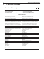
4. EU declaration of conformity . . . . . . . . . . . . . . . . . . . . . . . . . . . . . . . . . . . . . . . . . 30
3001147-RSG-RSGC-NO-SE-UK 20200511
2

1. UK – Product information
Symbols:
The following symbols have been used in the manual to draw attention to hazards or risk of damage to the product.
Prohibition symbol:
Failure to observe instructions marked with a prohibition symbol may result in serious or fatal injury
Danger symbol:
!
Failure to observe instructions marked with a danger symbol may result in personal injury and/or damage to
the unit.
!
TO MINIMISE THE RISK OF FIRE, ELECTRIC SHOCK, OR PERSONAL INJURY, PLEASE OBSERVE THE FOLLOWING:
• Use the device correctly following the manufacturer’s instructions. If in doubt, contact the dealer.
• Prior to servicing the device: Disconnect the power and ensure it cannot accidentally be reconnected.
• Installation work should be carried out by qualied personnel in accordance with national regulations.
• Follow the manufacturer’s instructions for the device and general safety directions.
• This device must be earthed.
Disposal:
No special precautions. The product should be disposed of in accordance with national regulations governing
disposal of electronic waste.
1.1 System description
RSG/RSGC
The exodraft RSG type fan is used as part of the fail-safe ue system for open ued gas appliances, such as stoves and
domestic boliers. The RSGC type fan is used as part of a fail-safe ue system for closed appliances such as cookers and
oil-red and gas-red boilers. All gas appliances must be CE-certied.
The fan should be installed on a suitable external wall and its installation must be in accordance with all
necessary servicing, environmental and regulatory building regulations, BS Standards, local bylaws and legal
requirements.
Flue gas temperature: min. -20 °C to max. +180 °C
Ambient temperature: min. -20 °C to max. +40 °C
1.2 Construction and design
The exodraft chimney fan type RSG gives a downward discharge of the ue gases through secure grilles on the
underside of the fan housing. It is made from galvanised sheet metal, tted with a centrifugal impeller and air ow
sensors linked to a pressure dierential switch (PDS), ensuring correct airow when the appliance is used.
The fan unit is supplied with a 6 core heat resistant silicone cable, which is 3 metres long (RSG) or 4 metres long (RSGC).
3001147-RSG-RSGC-NO-SE-UK 20200511 UK • 3

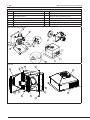
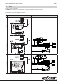
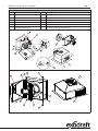
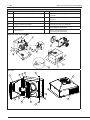
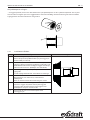
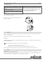
The RSG consists of the following main parts:
a) fan housing i) cooling impeller
b) motor k) screw to open hinged inner door
c) centrifugal impeller l) screw to open hinged outer door
d) pressure dierential switch (PDS) m) outlet grill
f) hinged outer door n) ow reducing plate (Not RSG250-4-1)
g) air ow sensor (-) o) screw for ow reducing plate. (Not RSG250-4-1)
h) air ow sensor (+) p) label: "Stay clear of hot surface"
RSG 125 / RSG 150 / RSG 200
RSG 250
a
kd
f
l
g
h
l
c
b
k
im
p
3001147-RSG-RSGC-NO-SE-UK 20200511
4 • UK

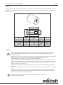
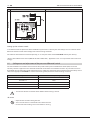
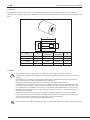
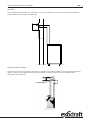
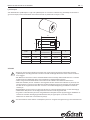
Silencer
A silencer type SLR can be supplied as an accessory. The silencer is round and has a length of min. 280 mm. Its outer
housing is made of galvanised sheet metal, insulated by mineral wool to a thickness of 50 mm with a perforated inner
steel sleeve.
N
M
O
P
FAN
TYPE MN
Inside
O
inside P
SLR125 280 Ø128 Ø125 Ø240
SLR150 280 Ø153 Ø150 Ø265
SLR200 280 Ø206 Ø203 Ø318
SLR250 280 Ø256 Ø253 Ø370
CAUTION
• RSG/C should not be mounted directly on a timber wall or any other walls of inammable material.
• The silencer and the ue pipe should not be in contact with any inammable material when it is
installed in the wall.
• When the fan is installed in a timber framed house, the recommendations of Institute of Gas Engineers
publication UP-7 ”Gas installations in timber framed buildings” should be observed.
• RSG and RSGC fans are not to be installed with solid fuel appliances.
• With DFE replace installations above 7kW input, an airbrick or similar fresh air inlet must be tted in
the room in which the replace is installed and must have an area of not less than 100 cm2 (15.5 in2).
The air vent must be either direct to outside air or to an adjacent room which itself has a vent direct to
outside air of at least the same area.
• The fan unit should be located on the external wall so it gets a minimum exposure to prevailing wind
conditions.
• The fan unit should be situated at a place, which alow the exhaust gasses to evacuate to surrrounding
air.
• Due to the risk of hot surfaces, it is required according to EN294 that a terminal guard is used on the
external wall where the fan is installed in frequented areas below 2.7 m (9 ft) from the ground level.
The fan has a label warning of hot surfaces (p).
• All installations must be carried out by competent personnel in accordance with
national laws and regulations.
!
3001147-RSG-RSGC-NO-SE-UK 20200511 UK • 5

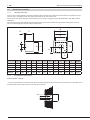
1.3 Mechanical assembly
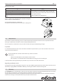
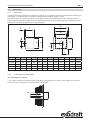
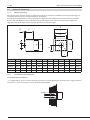
1.3.1 Location of the fan
In the case of a room without a chimney, decide the nal location of the appliance. Check that the fan position on the
external wall is acceptable. Mark the centre of the ue exit on the internal wall.
Use this centre to make cutting lines for the ue pipe or silencer using dimensions for fan RSG125, 150, 200 or 250 as
applicable.
The hole through the wall should provide minimum 5 mm clearance between the wall and the ue pipe or silencer.
Drill and cut through the internal and the external wall.
GC
F
E
B
D
J
A
L
K
H
A B C D E F G H J K L Weight
RSG125 265 250 220 336 320 121 35 280 296 153 157 11 Kg
RSGC150 325 310 240 400 380 125 35 340 360 181 186 14 Kg
RSG150 325 310 240 400 380 146 35 340 360 181 186 14 Kg
RSG200 405 380 275 478 453 196 35 413 438 215 221 20 Kg
RSG250 522 482 338 600 560 247 40 516 556 271 279 31 Kg
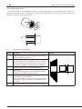
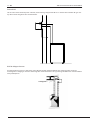
1.3.2 Installation of the silencer
If the silencer is shorter ...
... than the wall thickness, use the location brackets supplied with the silencer to secure it in the wall. It is possible to use
two of the holes and screws, which are used to secure the fan.
3001147-RSG-RSGC-NO-SE-UK 20200511
6 • UK

If the silencer is longer ...
.... than the wall, unscrew the retaining screws at the end of the silencer. Lift o the end plate. Cut the outer and inner
pipe so the length ts the wall thickness. Trim o excess mineral wool insulation and mount the inlet plate. Continue
the installation as described below.
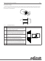
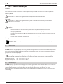
1.3.3 Installation of the fan
Step Action Drawing
1 Place the fan (silencer) through the hole from the outside.
Mark o the four holes of the fan ange on the external
wall (see gure and table at page 6).
2 Remove fan assembly, drill holes and insert rawlplugs
supplied. Apply mastic to the underside of the ange,
replace fan assembly and anchor it rmly to the wall with
the four screws supplied. (Not supplied with RSG250)
3 Connect the ue pipe to the silencer on the inlet side of the
fan.
Use ue cement to make airtight connections.
4 Make sure that:
the gas seal, if any, ts tightly around the silencer
the fan is mounted with the outlet facing downwards
5 Pack 50 mm mineral wool around the part of the ue pipe
which is located in the wall. The cavity between the outer
and the inner brick leaf and the space between the brick
walls and the silencer should be lled with mineral wool.
6 Finish by packing ush with the internal wall face.
3001147-RSG-RSGC-NO-SE-UK 20200511 UK • 7

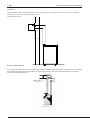
Only RSGC
The long copper tube must be piped into the room where the gas or oil appliance is situated to sense the reference
pressure in the room. The length of the tube can be
extended if necessary.
RSG for capped chimney
A sealing plate must be located in the chimney approximately 100 mm above the hole for the chimney box. The sealing
plate should be rmly inserted into the ue wall and properly sealed. It must be established that there are no leaks.
Install the fan without the silencer.
3001147-RSG-RSGC-NO-SE-UK 20200511
8 • UK

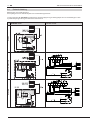
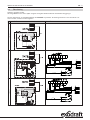
1.4 Wiring
The fan is variably adjustable.
All exodraft fans require extra safeguards in accordance with power current regulations.
For further details, please see guidelines for the exodraft control units.The diagrams shows the connection of the
6-core cable in the terminal box on the motor.
exodraft motor Grundfos motor
RSG125RSG150 / RSGC150
87 6 5 4 321
AUX
MAIN
P
BN
BK
BU
4
5
3
1
2
1
2
3
4
NO
NC
C
N
L1 5
YEGN
POWER SUPPLY
1 x 230 V ~ 50 Hz
6 x 0,75
BK
BN
BU
3 x 0,75
YEGN
RSG200
87 6 5 4 321
AUX
MAIN
t°
P
BN
BK
BU
4
5
3
1
2
1
2
3
4
NO
NC
C
N
L1 5
YEGN
POWER SUPPLY
1 x 230 V ~ 50 Hz
6 x 0,75
BK
BN
BU
3 x 0,75
YEGN
3001147-RSG-RSGC-NO-SE-UK 20200511 UK • 9

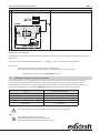
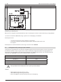
exodraft motor Grundfos motor
RSG250
Setting up the isolation switch:
In accordance with the provisions of the EU Machinery Directive* a chimney fan must always have an isolation switch
tted. The isolation switch must comply with national wiring standards.
The isolation switch must be ordered separately, as it is not part of the standard exodraft chimney fan delivery.
*Please refer to Machine Directive (2006/42/EF/-EEC/-EWG/-CEE) – Appendix 1 item 1.6.3 “Separation of the sources of
energy”.
1.5 Spillage test and adjustment of the pressure dierential switch
The test should be carried out to ensure that the fan speed and the pressure dierential switch (PDS) have been
correctly set for the appliance. This should be made with all the doors and windows closed. If any extractor fans have
been tted, the test should be made with these fans on. If spillage is detected, the fan speed must be turned up. Please
refer to the appropriate exodraft fan control installation guides, for further commissioning assistance.
Type PDS Factory setting
RSG125-4-1 30 Pa
RSG150-4-1 90 Pa
RSG200-4-1 60 Pa
RSG250-4-1 60 Pa
RSGC150-4-1 Fix 10/20 Pa
• Turn the fan o at the isolation switch before commisioning is startet.
Be aware
• Open the fan cover for setting the PDS
• Start and run the fan as described in the control manual
• Be aware that the cooling vane on the motor is running
!
3001147-RSG-RSGC-NO-SE-UK 20200511
10 • UK

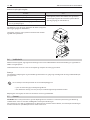
Reduced fan speed
If.... then....
- the RMS voltage to fan motor is under 160 V
- the outlet grill can be adjusted in order to enable the
RSG/C to work with low fan speed and still have the fail-
safe system working.
(Not an option on the RSG250-4-1)
- no spillage has been detected
- the PDS is adjusted to the factory setting
- the fail-safe system sometimes, or always, turns the gas
o
There is a plate on the underside for this purpose (see gure).
(Not an option on the RSG250-4-1)
Turn the plate to position II, commission
the system as described above and check with a spillage test.
1.6 Maintenance
The motor has special ball bearings that are sealed, lifetime lubricated and maintenance-free. If replacement of the
bearings is required, this should be carried out by qualied professionals.
The run capacitor is considered a wear part and will need to be replaced depending on usage.
Inspection
It is recommended that the fan and its connections should be inspected once a year at the same time as the annual
maintenance of the appliance.
Turn the fan o at the isolation switch before any maintenance work
commences.
• Remove all soot deposits on the impeller and the sensors.
• On inspection, care should be taken that the ow measuring system is not damaged.
In open position, the hinged chimney fan provides easy access for service and maintenance.
Regarding installations in UK:
Gas appliances should be checked for safety once a year by a CORGI registered Installer. Details of local installers can be
obtained by ringing CORGI on 0870 401 2300 or by accessing the website at www.trustcorgi.com.
1.7 Warranty
The exodraft RSG/C is provided with a two-year warranty. The fan must be installed by competent personnel and must
be used and serviced strictly in accordance with the installation instructions supplied.
Having commissioned the system and demonstrated to the end-user how to use it, leave the installation instructions
with the user. Changes in the specications may take place without notice.
3001147-RSG-RSGC-NO-SE-UK 20200511 UK • 11

2. NO – Produkt informasjon
Symboler:
Disse symbolene er brukt i manualen for å gjøre oppmerksom på risiko for personfare eller skade på produktet.
Forbudssymbol:
Overtredelse av anvisninger angitt med et forbudssymbol er forbundet med livsfare
Faresymbol:
!
Overtredelse av anvisninger angitt med et faresymbol er forbundet med risiko for personskade eller
ødeleggelse av materiell.
!
FOR Å MINIMERE RISIKOEN FOR BRANN, ELEKTRISK STØT ELLER PERSONSKADE BØR FØLGENDE REGLER
FØLGES:
• Bruk enheten korrekt som beskrevet av produsenten. Ved spørsmål kontakt forhandleren.
• Før det utføres service og vedlikehold på enheten: Slå av strømmen og sørg for at ingen kan slå strøm-
men på igjen utilsiktet.
• Installasjonsarbeid bør bare utføres av kompetente personer og etter gjeldende nasjonale regler og
forskrifter.
• Følg produsentens anvisninger og generelle sikkerhetsanvisninger for enheten.
• Denne enheten må jordes i installasjonen.
Fjerning:
Ingen spesielle forholdsregler. Produktet bør ernes i samsvar med nasjonale forskrifter for erning av
elektronisk avfall.
2.1 Beskrivelse
RSG/RSGC
exodraft røyksuger type RSG brukes som del av et failsafe-avtrekkssystem for gassapparater med åpne røykkanaler
som f.eks. gassovner og gasskjeler i private boliger. RSGC røyksuger brukes som del av et failsafe-avtrekkssystem
for gassapparater med lukkede røykkanaler som f.eks. visse komfyrer og olje- og gassfyrte varmtvannskjeler. Alle
gassapparater må være CE-godkjent.
Røyksugeren installeres på en egnet yttervegg, og installasjonen skal utføres i samsvar med alle gjeldende
forskrifter for vedlikehold og miljø samt alle gjeldende standarder samt nasjonale og lokale forskrifter.
Røykgasstemperatur: min. -20 °C til maks. +180 °C
Omgivelsestemperatur: min. -20 °C til maks. +40 °C
2.2 Konstruksjon
exodraft røyksuger type RSG avleverer røykgassene nedover gjennom et sikkert gitter på undersiden av viftehuset.
Den er laget i galvanisert metallplate, utstyrt med sentrifugalhjul og har et strømningsmålesystem som består av
strømningsfølere tilkoblet en pressostat (PDS) som sikrer korrekt luftstrøm når gassapparatet er i bruk.
Røyksugeren forsynes med matespenning gjennom en 3 m (RSG) eller 4 m (RSGC) lang 6-leders varmebestandig
silikonledning.
3001147-RSG-RSGC-NO-SE-UK 20200511
12 • NO

Røyksuger type RSG består av følgende hovedkomponenter:
a) viftehus i) kjølevifte
b) motor k) skrue for å åpne hengslet indre dør
c) sentrifugalhjul l) skrue for å åpne hengslet ytre dør
d) pressostat (PDS) m) avkastgitter
f) hengslet ytre dør n) strømningsreduksjonsplate (Ikke RSG250 4-1)
g) luftstrømningsmåler (-) o) skrue for strømningsreduksjonsplate (Ikke RSG250 4-1)
h) luftstrømningsmåler (+) p) advarsel: "Stay clear of hot surface"
RSG 125 / RSG 150 / RSG 200
RSG 250
a
kd
f
l
g
h
l
c
b
k
im
p
3001147-RSG-RSGC-NO-SE-UK 20200511 NO • 13

Lyddemper
En lyddemper av typen SLR kan leveres som tilbehør. Lyddemperen har rundt tverrsnitt og er min. 280 mm lang.
Lyddemperhuset er laget i galvanisert metallplate utvendig, isolert med 50 mm mineralullplate med en perforert indre
hylse.
N
M
O
P
FAN
TYPE MN
innvendig
O
innvendig P
SLR125 280 Ø128 Ø125 Ø240
SLR150 280 Ø153 Ø150 Ø265
SLR200 280 Ø206 Ø203 Ø318
SLR250 280 Ø256 Ø253 Ø370
ADVARSEL
• RSG/C bør ikke monteres direkte på en trevegg eller annen vegg av brennbart materiale.
• Lyddemperen og røykkanalen bør ikke være i berøring med brennbare materialer når de er installert i
veggen.
• Når røyksugeren er installert i et trehus, bør anbefalingene i Institute of Gas Engineers publication
UP-7 ”Gas installations in timber framed buildings” overholdes.
• Røyksugerne RSG og RSGC bør ikke brukes i installasjoner beregnet for fast brensel.
• Ved dekorative peisinstallasjoner med mer enn 7 kW eekt må det installeres en friskluftventil i rom-
met som peisen er installert i, med et areal på ikke mindre enn 100 cm2. Luftventilen må enten venti-
lere til friluft eller til et tilstøtende rom som har en ventil direkte ut til friluft med minst samme areal.
• Røyksugeren bør være montert på en yttervegg på en slik måte at den kun i minimal grad sjeneres av
de herskende vindforhold.
• Røyksugeren bør installeres på en plass, som gjør det mulig for røykgassen å forsvinne ut i lufta.
• På grunn av faren for varme overader er det ifølge EN294 påkrevet med skjerming på ytterveggen
hvis viften er installert ved beferdet areal og mindre enn 2,7 m over bakken.
Viften er forsynt med en advarsel om strømførende deler (p).
• Alle installasjoner må utføres av faglært personell i samsvar med gjeldende nasjonale regler og forskrifter.
!
3001147-RSG-RSGC-NO-SE-UK 20200511
14 • NO

2.3 Montering
2.3.1 Plassering
I rom uten skorstein bestemmes den endelige plasseringen av gassapparatet. Kontroller at røyksugerens plassering på
ytterveggen er akseptabel. Merk av sentrum av røykgasskanalen utløp på veggens innside.
Bruk senterpunktet til å merke opp skjærelinjer for røykgasskanalen eller lyddemperen for hhv. røyksuger RSG125,
150 eller 200. Hullet gjennom veggen skal ha en minimumsklaring på 5 mm mellom veggen og avtrekkskanalen eller
lyddemperen. Bor og skjær gjennom inner- og ytterveggen.
GC
F
E
B
D
J
A
L
K
H
A B C D E F G H J K L Vekt
RSG125 265 250 220 336 320 121 35 280 296 153 157 11 Kg
RSGC150 325 310 240 400 380 125 35 340 360 181 186 14 Kg
RSG150 325 310 240 400 380 146 35 340 360 181 186 14 Kg
RSG200 405 380 275 478 453 196 35 413 438 215 221 20 Kg
RSG250 522 482 338 600 560 247 40 516 556 271 279 31 Kg
2.3.2 Installasjon av lyddemperen
Hvis lyddemperen er kortere ...
... enn veggen er tykk, brukes holdebeslagene som følger med lyddemperen til å feste den til veggen. Det er mulig å
bruke to av hullene og skruene som brukes til å feste røyksugeren.
3001147-RSG-RSGC-NO-SE-UK 20200511 NO • 15

Hvis lyddemperen er lengre ...
… enn veggen er tykk, skru ut holdeskruene på den ene enden av lyddemperen. Ta av endeplaten. Skjær av inner- og
ytterrøret slik at lengden passer til veggtykkelsen. Skjær av overskytende mineralullsisolering og monter innløpsplaten.
Fortsett installasjonen som beskrevet under.
2.3.3 Installasjon av røyksugeren
Trinn Handling Tegning
1 Før røyksugeren (lyddemperen) gjennom hullet fra utsiden.
Merk av de re hullene i røyksugerensen på ytterveggen
(se gur og skjema på side 15).
2 Fjern røyksugeren, bor hullene og sett ev. i murpluggene
som følger med. Ha tetningsmiddel på ensens underside,
sett inn røyksugeren og fest den godt til veggen med de
re skruene som følger med. (Følger ikke med RSG250)
3 Kobl avtrekksrøret til lyddemperen på viftens innløpsside.
Bruk skorsteinslim for å sikre lufttette forbindelser.
4 Sørg for at:
en ev. gassforsegling passer tett rundt lyddemperenkkk
røyksugeren er montert med avkastet ned
5 Pakk 50 mm mineralull rundt den delen av avtrekksrøret
som benner seg inne i veggen.
Hulrommet mellom ytre og indre murvange og klaringen
mellom murveggen og lyddemperen bør også fylles med
mineralull.
6 Avslutt ved å pakke isoleringen jevnt med innerveggen.
3001147-RSG-RSGC-NO-SE-UK 20200511
16 • NO

Bare RSGC
Det lange kobberrøret skal føres inn i rommet hvor gass- eller oljeapparatet er plassert, for å måle referansetrykker i
rommet. Røret på kan forlenges om nødvendig.
RSG for skorstein med hatt
Det må plasseres en forseglingsplate i skorsteinen ca. 100 mm over hullet for takboksen. Forseglingsplaten bør settes
godt inn i veggen på avtrekkskanalen og forsegles ordentlig. Kontroller at det ikke er noen lekkasjer. Installer
røyksugeren uten lyddemper
Forseglingsplate
3001147-RSG-RSGC-NO-SE-UK 20200511 NO • 17

2.4 Elektrisk tilkobling
Røyksugeren er trinnløst justerbar.
Alle reyksugere krever ekstrabeskyttelse iht. sterkstrømsreglementet.
Se retningslinjene for exodraft styreenheter for nærmere opplysninger. Koblingsskjemaene viser tilkoblingen av den
6-polede forsyningsledningen til motorens klemmekasse.
exodraft motor Grundfos motor
RSG125RSG150 / RSGC150
87 6 5 4 321
AUX
MAIN
P
BN
BK
BU
4
5
3
1
2
1
2
3
4
NO
NC
C
N
L1 5
YEGN
POWER SUPPLY
1 x 230 V ~ 50 Hz
6 x 0,75
BK
BN
BU
3 x 0,75
YEGN
RSG200
87 6 5 4 321
AUX
MAIN
t°
P
BN
BK
BU
4
5
3
1
2
1
2
3
4
NO
NC
C
N
L1 5
YEGN
POWER SUPPLY
1 x 230 V ~ 50 Hz
6 x 0,75
BK
BN
BU
3 x 0,75
YEGN
3001147-RSG-RSGC-NO-SE-UK 20200511
18 • NO

exodraft motor Grundfos motor
RSG250
Montering av servicebryte
Vær oppmerksom på at det i henhold til Maskindirektivet*) skal monteres en servicebryter i den faste installasjonen av
røyksugeren.
*) Det henvises til “Maskindirektivet, 2006/42/ EF“ – vedlegg 1 – pkt. 1.6.3 “Atskillelse av energikildene“.
Bryteren skal:
• være låsbar eller plasseres synlig i nærheten av røyksugeren
• kunne bryte alle poler fra matespenningen – kontaktavstand min. 3 mm i hver pol.
Servicebryteren er ikke en del av exodraft-leveransen.
2.5 Lekkasjetest og justering av pressostaten
Testen bør utføres for å sikre at røyksugerens hastighet og pressostaten (PDS) er korrekt innstilt for det aktuelle
gassapparatet. Testen bør utføres med alle dører og vinduer stengt. Dersom det er montert avtrekksvifter, bør
testen utføres med disse viftene i gang. Dersom det konstateres lekkasje, må hastigheten på røyksugeren økes. Se
installasjonsveiledningen for den aktuelle exodraft røyksugerens styreenhet for nærmere informasjon.
Type PDS fabrikkinnstilling
RSG125-4-1 30 Pa
RSG150-4-1 90 Pa
RSG200-4-1 60 Pa
RSG250-4-1 60 Pa
RSGC150-4-1 Fast 10/20 Pa
• Slå av viften ved bruk av servicebryteren før justeringen av PDS går igang.
OBS
• Åpne røyksugeren for å justere PDS’en
• Start vifta som beskrevet I regulator manualen
• Vær oppmerksom på at motorens kjølehjul er igang
!
3001147-RSG-RSGC-NO-SE-UK 20200511 NO • 19

Redusert røyksugerhastighet
Dersom... skal...
- RMS-spenningen til røyksugermotoren er under 160 V
- avkastgitteret justeres slik at RSG/C kan gå med lav
viftehastighet og fortsatt ha failsafe-system aktivert
(Ikke tilgjengelig på en RSG250 4-1)
- det ikke nnes lekkasjer
- pressostaten PDS settes på fabrikkinnstillingen
- dersom failsafe-systemet noen ganger eller hele tiden,
slår av gassforsyningen
Det benner seg en plate på undersiden for dette (se guren).
(Ikke tilgjengelig på en RSG250 4-1)
Sett platen i stilling II, start systemet som beskrevet ovenfor
og utfør lekkasjekontroll.
2.6 Vedlikehold
Motoren har forseglede, engangssmurte kulelagre som er helt vedlikeholdsfrie. Eventuell utskifting av lagre bør bare
utføres av fagekspertise.
Driftskondensatoren anses å være en slitasjedel og må byttes ut avhengig av bruken.
Ettersyn
Det anbefales at røyksugeren og alle tilkoblinger kontrolleres en gang årlig samtidig med det årlige vedlikeholdet på
gassapparatet.
Slå av viften på servicebryteren før alt servicearbeid påbegynnes.
• Fjern alle sotavleiringer på viftehjulet og følerne.
• Når det foretas ettersyn, må man passe på at strømningsmålesystemet ikke skades.
Røyksugeren er hengslet, slik at det er lett å foreta service og vedlikehold.
2.7 Garanti
exodraft RSG/C er utstyrt med to års garanti. Røyksugeren må installeres av autorisert personell og må brukes og
vedlikeholdes i samsvar med den medfølgende installasjonsveiledningen.
Når systemet er satt i drift og sluttbrukeren har blitt instruert i hvordan det skal brukes, skal installasjonsveiledningen
overdras til brukeren. Spesikasjonene kan endres uten varsel.
3001147-RSG-RSGC-NO-SE-UK 20200511
20 • NO
Sidan laddas...
Sidan laddas...
Sidan laddas...
Sidan laddas...
Sidan laddas...
Sidan laddas...
Sidan laddas...
Sidan laddas...
Sidan laddas...
Sidan laddas...
Sidan laddas...
Sidan laddas...
-
 1
1
-
 2
2
-
 3
3
-
 4
4
-
 5
5
-
 6
6
-
 7
7
-
 8
8
-
 9
9
-
 10
10
-
 11
11
-
 12
12
-
 13
13
-
 14
14
-
 15
15
-
 16
16
-
 17
17
-
 18
18
-
 19
19
-
 20
20
-
 21
21
-
 22
22
-
 23
23
-
 24
24
-
 25
25
-
 26
26
-
 27
27
-
 28
28
-
 29
29
-
 30
30
-
 31
31
-
 32
32


på andra språk
- English: Exodraft RSG Owner's manual
- dansk: Exodraft RSG Brugervejledning
