
Version 04/23 Ident. no. Y05-0614
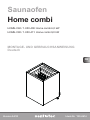
INSTRUCTIONS FOR INSTALLATION AND USE
English
EN
DE
FR
IT
NL
CS
SV
FI
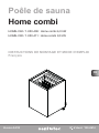
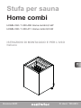
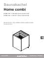
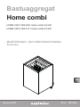
Sauna heater
Home combi
HOME-C60 / 1-050-408: Home combi 6.0 kW
HOME-C90 / 1-050-411: Home combi 9.0 kW

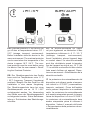
EN: Overheat protector of the device can
go o also at temperatures below -5˚C /
23˚F (storage, transport, environment).
Before installation take the device to the
warm environment. The overheat protector
can be reset when the temperature of the
device is approx 18˚C / 64˚F. The over-
heat protector must be reset before using
the device. See the user manual > Reset-
ting the Overheat Protector.
DE: Der Überhitzungsschutz des Geräts
kann auch bei Temperaturen unter -5 °C
/ 23˚F (Lagerung, Transport, Umgebung)
auslösen. Bringen Sie das Gerät vor der
Installation in eine warme Umgebung.
Der Überhitzungsschutz kann bei einer
Gerätetemperatur von ca. 18 °C / 64˚F
zurückgesetzt werden. Vor Verwendung
des Geräts muss der Überhitzungsschutz
zurückgesetzt werden. Siehe Betriebsan-
leitung > Zurücksetzen des Überhitzungs-
schutzes.
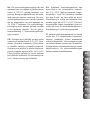
FR: La sécurité-surchaue de l’appa-
reil peut également se déclencher à des
températures inférieures à -5 ˚C / 23 ˚F
(stockage, transport, environnement).
Avant l’installation, placez l’appareil dans
un endroit chaud. La sécurité-surchaue
peut être réinitialisée quand la tempéra-
ture de l’appareil se situe à env. 18 ˚C / 64
˚F. La sécurité-surchaue doit être réinitia-
lisée avant d’utiliser cet appareil. Repor-
tez-vous au manuel > Réinitialisation de la
sécurité-surchaue.
IT: La protezione da surriscaldamento del
dispositivo può attivarsi anche a tempera-
ture inferiori a -5°C/23°F (conservazione,
trasporto, ambiente). Prima dell’installa-
zione, portare il dispositivo in un ambiente
caldo. La protezione da surriscaldamento
può essere reimpostata quando la tempe-
ratura del dispositivo è di circa 18˚C/64˚F.
La protezione da surriscaldamento deve
essere reimpostata prima di utilizzare il
dispositivo. Vedere il manuale dell’utente
> Reimpostazione della protezione da sur-
riscaldamento.
!

EN
DE
FR
IT
NL
CS
SV
FI
NL: De oververhittingsbeveiliging van het
apparaat kan ook afgaan bij temperaturen
onder -5 ˚C/23 ˚F (opslag, transport, om-
geving). Breng het apparaat vóór de instal-
latie naar een warme omgeving. De over-
verhittingsbeveiliging kan worden gereset
als de temperatuur van het apparaat ca.
18 ˚C/64 ˚F bedraagt. De oververhittings-
beveiliging moet worden gereset voordat
u het apparaat gebruikt. Zie de gebrui-
kershandleiding > Oververhittingsbeveili-
ging resetten.
CS: Ochrana proti přehřátí se také může
vypnout při teplotách pod -5˚C / 23˚F (skla-
dování, přeprava, prostředí). Před instala-
cí umístěte zařízení do teplého prostředí.
Ochranu proti přehřátí je možné resetovat,
pokud je teplota zařízení přibl. 18˚C / 64˚F.
Před použitím zařízení je nutné ochranu
proti přehřátí resetovat. Viz uživatelský ná-
vod > Reset ochrany proti přehřátí.
SV: Enhetens överhettningsskydd kan
även lösa ut när temperaturen understi-
ger -5˚C / 23˚F (lagring, transport, omgiv-
ningsmiljö). Innan du installerar enheten
bör den få stå i en varm miljö en stund.
Återställning är möjlig när enhetens tem-
peratur ligger på ca 18 ˚C / 64˚F. Överhett-
ningsskyddet måste återställas innan en-
heten tas i bruk. Se användarhandboken >
Återställning av överhettningsskyddet.
FI: Laitteen ylikuumenemissuoja voi laueta
myös alle -5˚C lämpötiloissa (varastointi,
kuljetus, ympäristö). Ennen asentamista
ota laite lämpimään. Ylikuumenemissuojan
voi kuitata laitteen ollessa noin 18 asteinen.
Kuittaa laitteen ylikuumenemissuoja ennen
käyttöönottoa > Ks. ylikuumenemissuojan
kuittaus laitteen käyttöohjeesta.

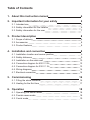
Table of Contents
1. About this instruction manual 4
2. Important information for your safety 5
2.1. Intended use 5
2.2. Safety information for the installer 6
2.3. Safety information for the user 7
3. Product description 8
3.1. Scope of delivery 8
3.2. Accessories 8
3.3. Product features 8
4. Installation and connection 8
4.1. Installation location and sensor position 9
4.2. Safety distances 9
4.3. Installation on the cabin wall 10
4.4. Connection diagram for 400 V 3 N~ 12
4.5. Connection diagram for 230 V 1 N~ 13
4.6. Wiring diagrams 14
4.7. Electrical connection 14
5. Commissioning 16
5.1. Filling the stone container 16
5.2. Heating for the rst time 17
6. Operation 18
6.1. Operating the sauna heater 18
6.2. Finnish sauna mode 18
6.3. Combi mode 19

EN
7. Maintenance 21
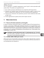
7.1. Extended periods of non-use 21
7.2. Cleaning the sauna heater 21
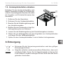
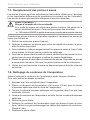
7.3. Changing the sauna stones 22
7.4. Cleaning the evaporator tank 22
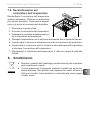
7.5. Descaling the evaporator tank 23
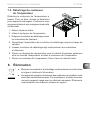
8. Disposal 23
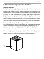
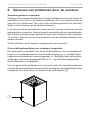
9. Problem-solving by the installer 24
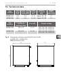
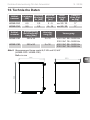
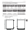
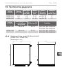
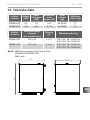
10. Technical data 25
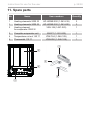
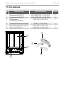
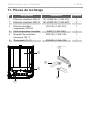
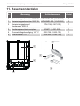
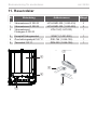
11. Spare parts 26

Instructions for installation and use p. 6/28
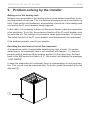
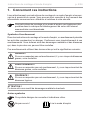
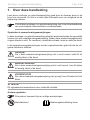
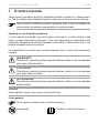
1. About this instruction manual
Carefully read these instructions for installation and use, and keep them near
the sauna. This ensures that you can refer to information on safety and operation
at any time.
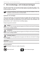
Symbols used for warning notices
In these instructions for installation and use, a warning notice located next to
an activity indicates that this activity poses a risk. Always observe the warning
notices. This prevents damage to property and injuries, which in the worst case
may be fatal.
The warning notices contain keywords, which have the following meanings:
DANGER!
Serious or fatal injury will occur if this warning notice is not observed.
WARNING!
Serious or fatal injury can occur if this warning notice is not observed.
CAUTION!
Minor injuries can occur if this warning notice is not observed.
NOTE!
This keyword is a warning that damage to property can occur.
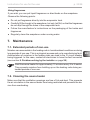
Other symbols
This symbol indicates tips and useful information.
Do not cover Read the operating instructions
These installation and operating instructions can also be found in
the downloads section of our website: www.sentiotec.com/downloads.

EN
Instructions for installation and use p. 7/28
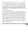
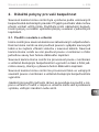
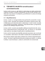
2. Important information for your safety
The Home combi sauna heater has been produced in accordance
with the applicable safety rules and regulations. However, hazards
may arise during use. Therefore adhere to the following safety infor-
mation and the specic warning notices in the individual chapters.
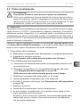
2.1. Intended use
The Home combi is a sauna heater with integrated evaporator.
The Home combi may only be used for heating sauna cabins and
for increasing the humidity inside the sauna cabin. The Home combi
may only be used in conjunction with a sauna control unit without
a remote start function.
The Home combi sauna heater can also be used with a sauna
control unit with a remote start function, but only in conjunction with
the optional safety shutdown feature.
The Home combi sauna heater can also be used in public saunas,
but only in conjunction with the optional safety shutdown feature.
Any use exceeding this scope is considered improper use. Improper
use can result in damage to the product, severe injuries or death.

Instructions for installation and use p. 8/28
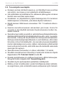
2.2. Safety information for the installer
●Installing and connecting the sauna heater may only be performed
when the power supply is disconnected.
●Installation may only be performed by a qualied electrician or
similarly qualied person.
●A fully disconnecting all-pole isolating device compliant with
overvoltage category III must be tted on site.
● Always use silicone cables that are heat-resistant up to 150 °C
to connect the sauna heater.
● Only install one sauna heater in the cabin. The Home n sauna
heater must not be used together with other sauna heaters in
a sauna cabin.
●The roof and walls of the sauna cabin must be manufactured from
low-resin, untreated or thermally treated wood, e.g. Nordic spruce,
hemlock, pine or r, or from laminated wooden materials. If lami-
nated wooden materials are used, make sure that the adhesive
used in them does not give o formaldehyde. If other materials
than wood are used in the sauna cabin, these materials must be
heat-resistant and corrosion-resistant and must not cause any
negative eects on the health of the sauna users.
● The height of the sauna cabin must be at least 1.9 m.
●Observe the specications on volumes and on ventilation of
the sauna cabin in chapter 10. Technical data on page 27.
●When positioning the sauna heater, observe the minimum safety
distances (see chapter 4.2. Safety distances).
●Also comply with the regulations applicable at the installation
location.
● For your own safety, consult your supplier in the event of prob-
lems that are not explained in sucient detail in the installation
instructions.

EN
Instructions for installation and use p. 9/28
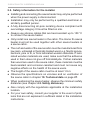
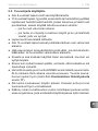
2.3. Safety information for the user
● The device must not be used by children under 8 years of age.
●The device may only be used by children over 8 years of age,
by persons with limited psychological, sensory or mental capa-
bilities or by persons with lack of experience/knowledge under
the following conditions:
– They are supervised.
– They have been shown how to use the device safely and
are aware of the hazards that could occur.
● Children must not play with the device.
●Children under 14 years of age may only clean the device if they
are supervised.
● For health reasons, do not use the sauna when under the inu-
ence of alcohol, medication or drugs.
●Never operate the sauna heater without sauna stones, as this
can cause res.
●Make sure that no ammable objects have been placed on the sau-
na heater before the sauna control unit is switched on.
●Heat up the sauna heater for half an hour BEFORE using the sau-
na for the rst time. Do NOT remain in the sauna cabin during
this period. Then ventilate the sauna cabin well (see 5.2. Heating
for the rst time on page 19).
●Never touch the sauna heater while it is operating. The surfaces
of the sauna heater and sauna stones become extremely hot.
●For your own safety, consult your supplier in the event of problems
that are not described in sucient detail in the user instructions.

Accessories Item number
Cut-o rocker switch SFE-350400 / 1-045-583
Instructions for installation and use p. 10/28
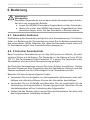
3. Product description
3.1. Scope of delivery
● Sauna heater
● Instructions for installation and use
3.2. Accessories
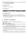
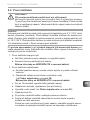
3.3. Product features
●Finnish sauna mode: usually 80 to 100 °C; approx. 10% rel. humidity
●Combi mode (only in combination with a combi control): approx. 40 to 65 °C,
35% to 70% humidity. The maximum permissible relative humidity decreases
with increasing temperature.
4. Installation and connection
Take the following points into account when positioning and connecting the sauna
heater:
●The electrical connection may only be performed by a qualied electrician or
similarly qualied person.
●A fully disconnecting all-pole isolating device compliant with overvoltage
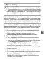
category III must be tted on site.
●The Home n sauna heater is a wall-mounted heater. Before starting the
heater, check that the heater has been rmly installed on the mounting rail.
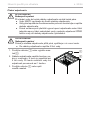
WARNING!
Danger of electric shock
●The sauna heater may only be installed and connected when the pow-
er supply is disconnected.

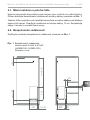
min 900
min 40
390
150
min 130
530
379
20
100
50
EN
Installation instructions, only for experts p. 11/28
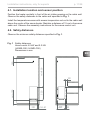
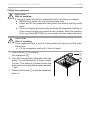
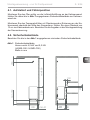
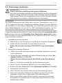
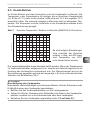
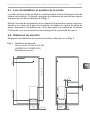
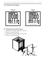
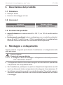
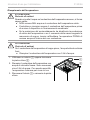
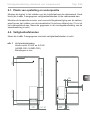
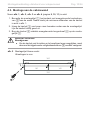
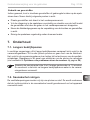
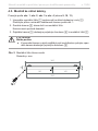
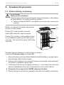
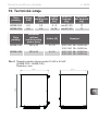
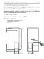
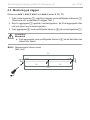
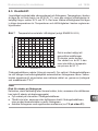
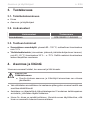
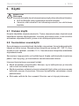
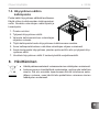
4.1. Installation location and sensor position
Position the heater centrally in front of the air intake opening on the cabin wall.
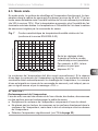
Observe the safety distances to the cabin wall specied in Fig. 1.
Install the temperature sensor with excess temperature cut-out to the cabin wall
above the centre of the sauna heater. Maintain a distance of 15 cm to the sauna
cabin roof. Observe the assembly instructions for the sauna control unit.
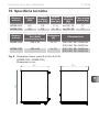
4.2. Safety distances
Observe the minimum safety distances specied in Fig. 1.
Fig. 1 Safety distances
Home combi 6.0 kW and 9.0 kW
(HOME-C60 / HOME-C90)
Dimensions in mm
405

Installation instructions, only for experts p. 12/28
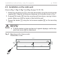
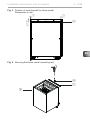
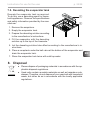
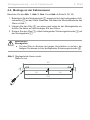
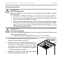
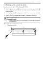
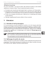
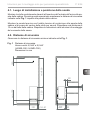
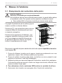
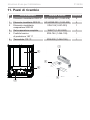
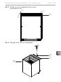
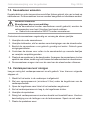
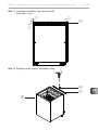
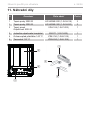
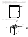
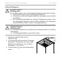
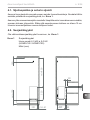
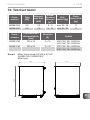
4.3. Installation on the cabin wall
Observe Fig. 1, Fig. 2, Fig. 3 and Fig. 4 (page 11, 12, 13).
1. Attach the mounting rail 1 to the wall horizontally using the wood screws
supplied 2. Observe the minimum distances for the heater shown in Fig. 1.
2. Suspend the heater 3 from the mounting rail from above, moving it down-
wards. Make sure that the heater is ush with the wall.
3. Secure the heater 3 using the lock screws supplied 4 on the mounting
rail 1.
Fig. 2 Mounting rail for Home combi
Dimensions in mm
WARNING!
Risk of re
●To x the heater in place and secure it against slippage, use the sup-
plied lock screw 4 for attachment.
160 160
360
320
8
18

EN
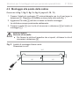
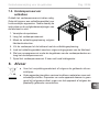
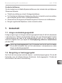
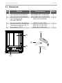
Installation instructions, only for experts p. 13/28
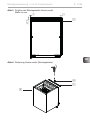
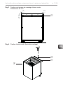
POSITION OF THE MOUNTING RAIL
27,5
15
15
Fig. 3 Position of mounting rail for Home combi
Dimensions in mm
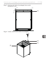
Fig. 4 Securing the Home combi (mounting rail)
1
3
4
1

3
Installation instructions, only for experts p. 14/28
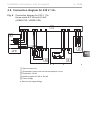
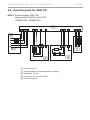
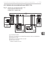
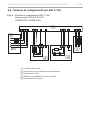
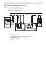
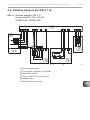
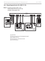
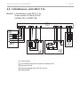
4.4. Connection diagram for 400 V 3 N~
Fig. 5
2
4
5
1
Connection diagram for 400 V 3 N~
Home combi 6.0 kW and 9.0 kW
(HOME-C60 / HOME-C90)
1 Sauna control unit
2 Temperature sensor with excess temperature cut-out
3 Evaporator 2.0 kW
4 6.0 kW or 9.0 kW Heating system
5 Power supply

EN
Installation instructions, only for experts p. 15/28
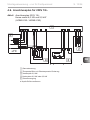
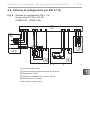
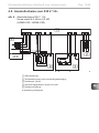
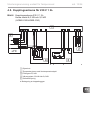
4.5. Connection diagram for 230 V 1 N~
*
Fig. 6 Connection diagram for 230 V 1 N~
Home combi 6.0 kW and 9.0 kW
(HOME-C60 / HOME-C90)
2
4
5
1
*
1 Sauna control unit
2 Temperature sensor with excess temperature cut-out
3 Evaporator 2.0 kW
4 Heating system 6.0 kW or 9.0 kW
5 Power supply
Remove the copper bridge
3

Installation instructions, only for experts p. 16/28
HOME-C90
9.0 kW
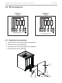
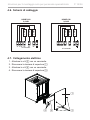
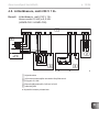
4.6. Wiring diagrams
HOME-C60
6.0 kW
U V W N
W
2,0kW
2,0kW
2,0kW
N
V
N
U
to the control unit
U V W N
W
3,0kW
3,0kW
3,0kW
N
V
N
U
to the control unit
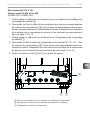
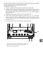
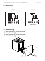
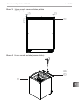
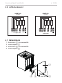
4.7. Electrical connection
1. Unscrew the screws 2 with a screwdriver.
2. Remove the cover plate 1.
3. Unscrew the screws 4 with a screwdriver.
4. Remove the cover plate 3.
1
32
4

EN
Installation instructions, only for experts p. 17/28
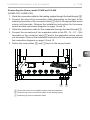
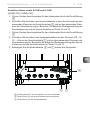
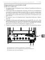
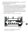
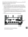
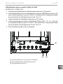
Connecting the Home combi 6.0 kW and 9.0 kW
(HOME-C60 / HOME-C90)
1. Guide the connection cable for the heating system through the feed-through 6.
2. Connect the wires of the connection cable (depending on the type) to the
matching terminals of the connector block 5 and to the appropriate sauna
control unit terminals. Observe the installation instructions for the sauna
control and the connection diagrams on page 14 and 15.
1. Guide the connection cable for the evaporator through the feed-through 7.
2. Connect the connectors of the evaporator cable to the PE – N – U1 – Wm
terminals on the connector block 5 and to the applicable sauna control
unit terminals. Observe the installation instructions for the sauna control and
the connection diagrams on page 14 and 15.
3. Fasten the cover plates 3 and 1 back on the sauna heater.
76
5
5 Connection block for the heating system and the evaporator
6 Feed-through for the connection cable of the heating system
7 Feed-through for the evaporator cable

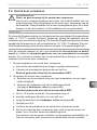
Instructions for use for the user p. 18/28
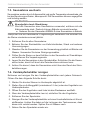
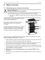
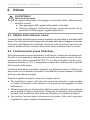
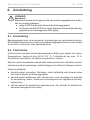
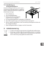
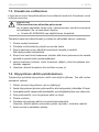
5. Commissioning
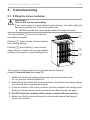
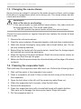
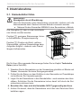
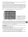
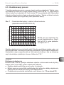
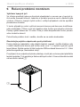
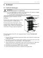
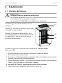
5.1. Filling the stone container
The amount of stones suited to your heater can be found in
chapter Technical data (see page 27).
1. Wash the stones thoroughly using water and a brush before use.
Do not use any cleaning additives.
2. Before lling the heater with the sauna stones, check them for foreign objects
and remove any remaining packaging.
3. Place the stones in the stone container and also between the heating rods.
Stack the sauna stones loosely so that air can ow through the gaps.
4. Do NOT allow the heating rods to make contact with one another.
5. Make sure that the sauna stones do not protrude beyond the edge of
the stone container.
WARNING!
Risk of re due to overheating
If the sauna heater is used without sauna stones, the cabin walls will
become extremely hot. This could cause res.
● NEVER operate the sauna heater without the sauna stones.
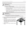
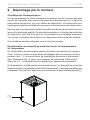
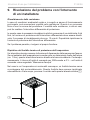
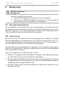
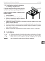
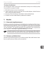
The stone basket 1 can be mounted at
two dierent heights.
Position 2: fewer stones, shorter heating
time, energy saving
Position 3 (set at factory): more stones,
larger amount of water for pouring possible,
creating more steam, longer heating times
1
3
2

EN
Instructions for use for the user p. 19/28
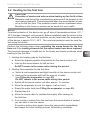
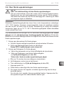
5.2. Heating for the rst time
CAUTION!
Formation of smoke and odours when heating up for the rst time
Materials used during the manufacturing process will be present on the
new heating elements. These evaporate when the sauna heater is heat-
ed up for the rst time. This produces smoke and an unpleasant odour.
Breathing in the fumes or smoke can be harmful to your health.
Perform the following steps when operating the sauna heater for the rst
time and if the heating elements for the sauna heater have been replaced.
This prevents damage to health due to the fumes and smoke produced when
heating for the rst time.
1. Heating the heating rods for the rst time
a. Select the highest possible temperature on the sauna control unit.
b. Heat up the sauna heater for half an hour.
Do NOT remain in the sauna cabin during this period.
2. Heating the evaporator for the rst time
a. Select a low temperature and high humidity on the sauna control unit.
b. Heat up the evaporator with half the amount of water
(see Filling the evaporator on page 20)
Do NOT remain in the sauna cabin during this period.
c. Switch o the sauna control unit after approx. 15 minutes.
d. Allow the evaporator to cool (for approx. half an hour).
e. Empty the water tank (see Filling the evaporator on page 20)
f. Repeat step 2.b.
g. Allow the sauna cabin to ventilate thoroughly after heating for
the rst time.
h. If no smoke or odours form the next time the sauna heater is heated,
you can start to use the sauna.
If smoke or odours form again, leave the sauna cabin immediately,
and repeat the initial heating process, followed by ventilation.
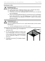
NOTE!
Overheat protector of the device can go o also at temperatures below -5˚C /
23˚F (storage, transport, environment). Before installation take the device to the
warm environment. The overheat protector can be reset when the temperature
of the device is approx 18˚C / 64˚F. The overheat protector must be reset be-
fore using the device.

Instructions for use for the user p. 20/28
WARNING!
Risk of re
Combustible objects that are placed on the heater will ignite and cause
res.
● NEVER place combustible objects on the sauna heater.
●Make sure that NO ammable objects have been placed on the heater
before operating it.
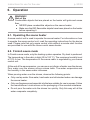
6. Operation
6.1. Operating the sauna heater
A sauna control unit is used to operate the sauna heater. For information on how
to operate the sauna control unit, read the operating instructions for the device
used. Please note that only sauna control units without a remote start function
are permitted for use with the Home combi sauna heater.
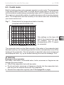
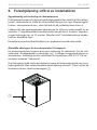
6.2. Finnish sauna mode
In Finnish sauna mode, only the heating system operates. Dry heat is produced.
The temperature in the cabin is high (80 to 100 °C). The maximum humidity level
of 10% is low. The temperature in the sauna cabin is regulated by your sauna
control unit.
At the end of the sauna session, you can pour an infusion of water over the stones.
Pour water over the stones using a sauna ladle. The water evaporates and
the humidity in the sauna cabin increases.
When pouring water over the stones, observe the following points:
●Only use tap water. Sea water, hard water and chlorinated water can damage
the sauna heater.
●Only use fragrances and essential oils that are suitable for use in saunas. Follow
the manufacturer’s instructions on the packaging of the scented substance.
●Do not pour the water onto the stones too quickly. Only this way will all the
water evaporate completely.
Sidan laddas...
Sidan laddas...
Sidan laddas...
Sidan laddas...
Sidan laddas...
Sidan laddas...
Sidan laddas...
Sidan laddas...
Sidan laddas...
Sidan laddas...
Sidan laddas...
Sidan laddas...
Sidan laddas...
Sidan laddas...
Sidan laddas...
Sidan laddas...
Sidan laddas...
Sidan laddas...
Sidan laddas...
Sidan laddas...
Sidan laddas...
Sidan laddas...
Sidan laddas...
Sidan laddas...
Sidan laddas...
Sidan laddas...
Sidan laddas...
Sidan laddas...
Sidan laddas...
Sidan laddas...
Sidan laddas...
Sidan laddas...
Sidan laddas...
Sidan laddas...
Sidan laddas...
Sidan laddas...
Sidan laddas...
Sidan laddas...
Sidan laddas...
Sidan laddas...
Sidan laddas...
Sidan laddas...
Sidan laddas...
Sidan laddas...
Sidan laddas...
Sidan laddas...
Sidan laddas...
Sidan laddas...
Sidan laddas...
Sidan laddas...
Sidan laddas...
Sidan laddas...
Sidan laddas...
Sidan laddas...
Sidan laddas...
Sidan laddas...
Sidan laddas...
Sidan laddas...
Sidan laddas...
Sidan laddas...
Sidan laddas...
Sidan laddas...
Sidan laddas...
Sidan laddas...
Sidan laddas...
Sidan laddas...
Sidan laddas...
Sidan laddas...
Sidan laddas...
Sidan laddas...
Sidan laddas...
Sidan laddas...
Sidan laddas...
Sidan laddas...
Sidan laddas...
Sidan laddas...
Sidan laddas...
Sidan laddas...
Sidan laddas...
Sidan laddas...
Sidan laddas...
Sidan laddas...
Sidan laddas...
Sidan laddas...
Sidan laddas...
Sidan laddas...
Sidan laddas...
Sidan laddas...
Sidan laddas...
Sidan laddas...
Sidan laddas...
Sidan laddas...
Sidan laddas...
Sidan laddas...
Sidan laddas...
Sidan laddas...
Sidan laddas...
Sidan laddas...
Sidan laddas...
Sidan laddas...
Sidan laddas...
Sidan laddas...
Sidan laddas...
Sidan laddas...
Sidan laddas...
Sidan laddas...
Sidan laddas...
Sidan laddas...
Sidan laddas...
Sidan laddas...
Sidan laddas...
Sidan laddas...
Sidan laddas...
Sidan laddas...
Sidan laddas...
Sidan laddas...
Sidan laddas...
Sidan laddas...
Sidan laddas...
Sidan laddas...
Sidan laddas...
Sidan laddas...
Sidan laddas...
Sidan laddas...
Sidan laddas...
Sidan laddas...
Sidan laddas...
Sidan laddas...
Sidan laddas...
Sidan laddas...
Sidan laddas...
Sidan laddas...
Sidan laddas...
Sidan laddas...
Sidan laddas...
Sidan laddas...
Sidan laddas...
Sidan laddas...
Sidan laddas...
Sidan laddas...
Sidan laddas...
Sidan laddas...
Sidan laddas...
Sidan laddas...
Sidan laddas...
Sidan laddas...
Sidan laddas...
Sidan laddas...
Sidan laddas...
Sidan laddas...
Sidan laddas...
Sidan laddas...
Sidan laddas...
Sidan laddas...
Sidan laddas...
Sidan laddas...
Sidan laddas...
Sidan laddas...
Sidan laddas...
Sidan laddas...
Sidan laddas...
Sidan laddas...
Sidan laddas...
Sidan laddas...
Sidan laddas...
Sidan laddas...
Sidan laddas...
Sidan laddas...
Sidan laddas...
Sidan laddas...
Sidan laddas...
Sidan laddas...
Sidan laddas...
Sidan laddas...
Sidan laddas...
Sidan laddas...
Sidan laddas...
Sidan laddas...
Sidan laddas...
Sidan laddas...
Sidan laddas...
Sidan laddas...
Sidan laddas...
Sidan laddas...
Sidan laddas...
Sidan laddas...
Sidan laddas...
Sidan laddas...
Sidan laddas...
Sidan laddas...
Sidan laddas...
Sidan laddas...
-
 1
1
-
 2
2
-
 3
3
-
 4
4
-
 5
5
-
 6
6
-
 7
7
-
 8
8
-
 9
9
-
 10
10
-
 11
11
-
 12
12
-
 13
13
-
 14
14
-
 15
15
-
 16
16
-
 17
17
-
 18
18
-
 19
19
-
 20
20
-
 21
21
-
 22
22
-
 23
23
-
 24
24
-
 25
25
-
 26
26
-
 27
27
-
 28
28
-
 29
29
-
 30
30
-
 31
31
-
 32
32
-
 33
33
-
 34
34
-
 35
35
-
 36
36
-
 37
37
-
 38
38
-
 39
39
-
 40
40
-
 41
41
-
 42
42
-
 43
43
-
 44
44
-
 45
45
-
 46
46
-
 47
47
-
 48
48
-
 49
49
-
 50
50
-
 51
51
-
 52
52
-
 53
53
-
 54
54
-
 55
55
-
 56
56
-
 57
57
-
 58
58
-
 59
59
-
 60
60
-
 61
61
-
 62
62
-
 63
63
-
 64
64
-
 65
65
-
 66
66
-
 67
67
-
 68
68
-
 69
69
-
 70
70
-
 71
71
-
 72
72
-
 73
73
-
 74
74
-
 75
75
-
 76
76
-
 77
77
-
 78
78
-
 79
79
-
 80
80
-
 81
81
-
 82
82
-
 83
83
-
 84
84
-
 85
85
-
 86
86
-
 87
87
-
 88
88
-
 89
89
-
 90
90
-
 91
91
-
 92
92
-
 93
93
-
 94
94
-
 95
95
-
 96
96
-
 97
97
-
 98
98
-
 99
99
-
 100
100
-
 101
101
-
 102
102
-
 103
103
-
 104
104
-
 105
105
-
 106
106
-
 107
107
-
 108
108
-
 109
109
-
 110
110
-
 111
111
-
 112
112
-
 113
113
-
 114
114
-
 115
115
-
 116
116
-
 117
117
-
 118
118
-
 119
119
-
 120
120
-
 121
121
-
 122
122
-
 123
123
-
 124
124
-
 125
125
-
 126
126
-
 127
127
-
 128
128
-
 129
129
-
 130
130
-
 131
131
-
 132
132
-
 133
133
-
 134
134
-
 135
135
-
 136
136
-
 137
137
-
 138
138
-
 139
139
-
 140
140
-
 141
141
-
 142
142
-
 143
143
-
 144
144
-
 145
145
-
 146
146
-
 147
147
-
 148
148
-
 149
149
-
 150
150
-
 151
151
-
 152
152
-
 153
153
-
 154
154
-
 155
155
-
 156
156
-
 157
157
-
 158
158
-
 159
159
-
 160
160
-
 161
161
-
 162
162
-
 163
163
-
 164
164
-
 165
165
-
 166
166
-
 167
167
-
 168
168
-
 169
169
-
 170
170
-
 171
171
-
 172
172
-
 173
173
-
 174
174
-
 175
175
-
 176
176
-
 177
177
-
 178
178
-
 179
179
-
 180
180
-
 181
181
-
 182
182
-
 183
183
-
 184
184
-
 185
185
-
 186
186
-
 187
187
-
 188
188
-
 189
189
-
 190
190
-
 191
191
-
 192
192
-
 193
193
-
 194
194
-
 195
195
-
 196
196
-
 197
197
-
 198
198
-
 199
199
-
 200
200
-
 201
201
-
 202
202
-
 203
203
-
 204
204
-
 205
205
-
 206
206
-
 207
207
-
 208
208
-
 209
209
-
 210
210
-
 211
211
-
 212
212


på andra språk
- italiano: Sentiotec Home combi Manuale utente
- slovenčina: Sentiotec Home combi Používateľská príručka
- eesti: Sentiotec Home combi Kasutusjuhend
- français: Sentiotec Home combi Manuel utilisateur
- Nederlands: Sentiotec Home combi Handleiding
Relaterade papper
-
Sentiotec Concept R mini combi Användarmanual
-
Sentiotec Concept R combi Användarmanual
-
-
-
-
-
-
-
-
Andra dokument
-
HARVIA sentiotec CP-RMC-35 Instructions For Installation And Use Manual
-
Tylö Sense Pure Användarmanual
-