Sentiotec CP-RB-090 Concept R Black Användarmanual
- Typ
- Användarmanual

Version 10/21 Ident. no. CP-RB-MA
INSTRUCTIONS FOR INSTALLATION AND USE
English EN
DE
FR
IT
NL
SV
CS
SL
FI
Sauna heater
Concept R black
CP-RB-090 / 1-027-768: Concept R 9.0 kW black
CP-RB-105 / 1-027-769: Concept R 10.5 kW black
CP-RB-120 / 1-027-770: Concept R 12.0 kW black
CP-RB-150 / 1-027-771: Concept R 15.0 kW black

Table of Contents
1. About this instruction manual 4
2. Important information for your safety 5
2.1. Intended use 5
2.2. Safety information for the installer 5
2.3. Safety information for the user 7
3. Product description 8
3.1. Scope of delivery 8
3.2. Accessories 8
3.3. Product functions 8
4. Installation and connection 9
4.1. Installation location and sensor position 9
4.2. Safety distances 10
4.3. Adjusting the height 11
4.4. Connection diagram for 400 V 3N~ 12
4.5. Connection diagram for 230 V 1N~ 14
4.6. Wiring diagrams 15
4.7. Electrical connection 17
5. Commissioning 19
5.1. Filling the stone container 19
5.2.Heatingforthersttime 20
6. Operation 21
6.1. Operating the sauna heater 21
6.2. Infusion 21

EN
7. Maintenance 22
7.1. Extended periods of non-use 22
7.2. Cleaning the sauna heater 22
7.3. Changing the sauna stones 22
8. Disposal 23
9. Problem-solving by the installer 24
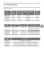
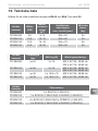
10. Technical data 25

Instructions for installation and use p. 4/26
1. About this instruction manual
Carefully read these instructions for installation and use, and keep them near
the sauna. This ensures that you can refer to information about your safety and
the operation at any time.
Symbols used for warning notices
In these instructions for installation and use, a warning notice located next to
an activity indicates that this activity poses a risk. Always observe the warning
notices. This prevents damage to property and injuries, which in the worst case
may be fatal.
The warning notices contain keywords, which have the following meanings:
DANGER!
Serious or fatal injury will occur if this warning notice is not observed.
WARNING!
Serious or fatal injury can occur if this warning notice is not observed.
CAUTION!
Minor injuries can occur if this warning notice is not observed.
ATTENTION!
This keyword is a warning that damage to property can occur.
Other symbols
This symbol indicates tips and useful information.
Do not cover Read the operating instructions
These installation and operating instructions can also be found in the down-
loads section of our website: www.sentiotec.com/downloads.

EN
Instructions for installation and use p. 5/26
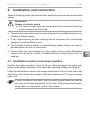
2. Important information for your safety
The Concept R sauna heater has been produced in accordance
with the applicable safety rules and regulations. However, hazards
may occur during use. Therefore adhere to the following safety in-
formationandthespecicwarningnoticesintheindividualchapters.
2.1. Intended use
The Concept R sauna heater is intended solely for heating sauna
cabins, in conjunction with a sauna control unit which does not
include a remote start function.
The Concept R sauna heater can also be used with a sauna control
unit with a remote start function, but only in conjunction with the
optional safety shutdown feature (CP-R-SWL).
The Concept R sauna heater can also be used in public saunas,
but only in conjunction with the optional safety shutdown feature
(CP-R-SWL).
Any use exceeding this scope is considered improper use. Improper
use can result in damage to the product, severe injuries or death.
2.2. Safety information for the installer
●Installing and connecting the sauna heater may only be performed
when the power supply is disconnected.
●Installationmayonlybeperformedbyaqualiedelectricianor
similarlyqualiedperson.
●A fully disconnecting all-pole isolating device compliant with
overvoltagecategoryIIImustbettedonsite.
●Always use silicone cables that are heat-resistant up to 150 °C
to connect the sauna heater.

Instructions for installation and use p. 6/26
●Only install one sauna heater in the cabin. The Concept R sauna
heater must not be used together with other sauna heaters in
a sauna cabin.
●The roof and walls of the sauna cabin must be manufactured
from low-resin, untreated or thermally treated wood, e.g. Nordic
spruce,hemlock,pineorr,orfromlaminatedwoodenmateri-
als. If laminated wooden materials are used, make sure that the
adhesiveusedinthemdoesnotgiveoformaldehyde.Ifother
materials than wood are used in the sauna cabin, these materi-
als must be heat-resistant and corrosion-resistant and must not
causeanynegativeeectsonthehealthofthesaunausers.
●The height of the sauna cabin must be at least 2.0 m.
● Observethespecicationsonvolumesandonventilationofthe
sauna cabin in chapter 10. Technical data.
●When positioning the sauna heater, observe the minimum safety
distances (see chapter 4.2. Safety distances).
●Also comply with the regulations applicable at the installation
location.
●For your own safety, consult your supplier in the event of prob-
lemsthatarenotexplainedinsucientdetailintheinstallation
instructions.

EN
Instructions for installation and use p. 7/26
2.3. Safety information for the user
●The device must not be used by children under 8 years of age.
●The device may only be used by children over 8 years of age,
by persons with limited psychological, sensory or mental capa-
bilities or by persons with lack of experience/knowledge under
the following conditions:
– They are supervised.
– They have been shown how to use the device safely and
are aware of the hazards that could occur.
●Children must not play with the device.
●Children under 14 years of age may only clean the device if they
are supervised.
● Forhealthreasons,donotusethesaunawhenundertheinu-
ence of alcohol, medication or drugs.
●Never operate the sauna heater without sauna stones, as this
cancauseres.
● Makesurethatnoammableobjectshavebeenplacedonthe
sauna heater before the sauna control unit is switched on.
●Heat up the sauna heater for half an hour BEFORE using the
saunaforthersttime.DoNOTremaininthesaunacabinduring
this period. Then ventilate the sauna cabin well (see 5.2. Heating
for the rst time on page 20).
●Never touch the sauna heater while it is operating. The surfaces
of the sauna heater and sauna stones become extremely hot.
●For your own safety, consult your supplier in the event of problems
thatarenotdescribedinsucientdetailintheuserinstructions.

Instructions for installation and use p. 8/26
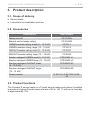
3. Product description
3.1. Scope of delivery
●Sauna heater
●Instructions for installation and use
3.2. Accessories
Accessories Item number
Safetyshut-o CP-R-SWL
Bracket set for heater railing CP-R-HSR
LINDEN wooden railing, small (9 – 10.5 kW) CP-R-L1
LINDEN wooden railing, large (12 – 15 kW) CP-R-L2
WALNUT wooden railing, small (9 – 10.5 kW) CP-R-N1
WALNUT wooden railing, large (12 – 15 kW) CP-R-N2
Emotion railingset LINDEN small (9 - 10,5 kW) CPR-EMO-L1
Emotion railingset LINDEN large (12 - 15 kW) CPR-EMO-L2
Emotion railingset WALNUT small
(9 - 10.5 kW)
CPR-EMO-N1
Emotion railingset WALNUT large
(12 - 15 kW)
CPR-EMO-N2
Power booster O-S2-18 / O-S2-18S /O-S2-
30
3.3. Product functions
The Concept R sauna heater is a Finnish sauna heater and makes it possible
to produce a typical Finnish sauna climate of 80 to 100 °C with an air humidity
of approximately 10%.

EN
Installation instructions, only for experts p. 9/26
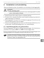
4. Installation and connection
Take the following points into account when positioning and connecting the sauna
heater:
Ifthereissucientventilation,theConceptRsaunaheatercanalsobe
setupasafree-standingdevice.Inthiscase,tthetemperaturesensor
to the cabin roof above the centre of the heater.
●Theelectricalconnectionmayonlybeperformedbyaqualiedelectricianor
similarlyqualiedperson.
●A fully disconnecting all-pole isolating device compliant with overvoltage
categoryIIImustbettedonsite.
●The Concept R sauna heater is a free-standing heater. It does not need to
beattachedtotheoororsaunawall.
●Donotplacethesaunaheateronaoormadefromaneasilyammable
materialsuchaswoodorplastic.Suitableooringincludesceramictiles,for
example.
4.1. Installation location and sensor position
Position the heater centrally in front of the air intake opening in the cabin wall.
ObservethesafetydistancestothecabinwallspeciedinFig. 1 and Fig. 2.
Install the temperature sensor with excess temperature cut-out to the cabin wall
above the centre of the sauna heater. Maintain a distance of 15 cm to the sauna
cabin roof.
WARNING!
Danger of electric shock
●The sauna heater may only be installed and connected when the
power supply is disconnected.

150
min.
1940
715-725
450446
min.
1215
min.
50
min.
50
Installation instructions, only for experts p. 10/26
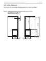
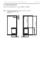
Fig. 1 Safety distances for Concept R 9 kW and 10.5 kW
(CP-RB-090 / CP-RB-105)
Measurements in mm
CP-RB-090
CP-RB-105
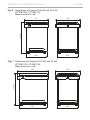
4.2. Safety distances
ObservetheminimumsafetydistancesspeciedinFig. 1 and Fig. 2.

min.
1940
450
min. 50
715-725
min. 50
150
590
min.
1215
EN
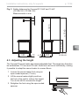
Installation instructions, only for experts p. 11/26
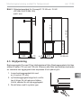
Fig. 2 Safety distances for Concept R 12 kW and 15 kW
(CP-RB-120 / CP-RB-150)
Measurements in mm
CP-RB-120
CP-RB-150
4.3. Adjusting the height
The Concept R sauna heater has height-adjustable feet. The height can therefore
be set between 715 mm and 725 mm. Each foot can be set individually, making
itpossibletoadaptthesaunaheatertounevenoors.
1. Loosen the sauna heater foot using an
open-ended spanner (13 mm).
2. Lift the sauna heater slightly and turn
the foot to the right to reduce the height.
Turn to the left to increase the height.
3. Retighten the foot using the open-ended
spanner.

L2 L2 N
L3 U
V
N
Wr
r
w
w
ϑϑ
400 V~
3x16 A
U
V
NW
WNVNU
Installation instructions, only for experts p. 12/26
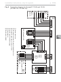
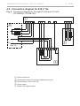
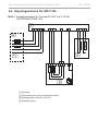
4.4. Connection diagram for 400 V 3N~
Fig. 3 Connection diagram for Concept R 9 kW and 10.5 kW
(CP-RB-090 / CP-RB-105)
2
3
4
1 Sauna control unit
2 Temperature sensor with excess temperature cut-out
3 Sauna heater, 9 kW or 10.5 kW
4 Power supply
1

L1 L2 N
L3 U
V
N
Wr
r
w
w
ϑϑ
U1
V1
N
W1
400 V~
3x16 A
12 kW und 15 kW
N
ST1
ST2
ST1
ST2
N
V2
W2
U2
L1 L2 N
L3
S2-18:
400 V~ 3x20 A
S2-18
S2-30
U2
V2
W2
S2-30:
400 V~ 3x35 A
N
ST3
EN
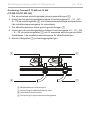
Installation instructions, only for experts p. 13/26
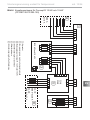
Fig. 4 Connection diagram for Concept R 12 kW and 15 kW
(CP-RB-120 / CP-RB-150)
1
2
3
4
5
6
1 Sauna control unit
2 Temperature sensor with excess temperature cut-out
3 Concept R sauna heater, 12 kW or 15 kW
4 Sauna control unit power supply
5 Power booster
6 Booster power supply
A12 kW and 15 kW

L1 L2 N
L3 U
V
N
Wr
r
w
w
ϑϑ
U
V
NW
W
230V 1N~
NVNU
L
PE
N
Installation instructions, only for experts p. 14/26
4.5. Connection diagram for 230 V 1N~
Connection diagram for Concept R 9 kW and 10.5 kW
(CP-RB-090 / CP-RB-105)
Fig. 5
1 Sauna control unit
2 Temperature sensor with excess temperature cut-out
3 Sauna heater, 9 kW or 10.5 kW
4 Power supply
Remove the copper bridge
1
4
3
2
*
*

EN
Installation instructions, only for experts p. 15/26
1,5 kW
1,5 kW
1,5 kW
U V W N
1,5 kW
1,5 kW
1,5 kW
CP-R-090
9,0 kW
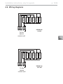
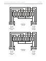
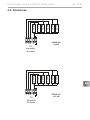
4.6. Wiring diagrams
1,5 kW
2,0 kW
1,5 kW
U V W N
2,0 kW
1,5 kW
2,0 kW
CP-R-105
10,5 kW
To the
sauna
control unit
To the
sauna
control unit
CP-RB-090
9.0 kW
CP-RB-105
10.5 kW

Installation instructions, only for experts p. 16/26
1,5 kW
1,5 kW
1,1 kW
U1V1W1
N
CP-R-120
12,0 kW
1,5 kW
1,5 kW
1,1 kW
N
V2
1,5 kW
1,5 kW
1,1 kW
U2
W2
To the
sauna
control unit
To the
power
booster
1,5 kW
1,5 kW
2,0 kW
U1V1W1
N
CP-R-150
15,0 kW
1,5 kW
1,5 kW
2,0 kW
N
V2
1,5 kW
1,5 kW
2,0 kW
U2
W2
To the
sauna
control unit
To the
power
booster
9 kW 3.3 kW
9 kW 6 kW
CP-RB-120
12.0 kW
CP-RB-150
15.0 kW

U
V
W
N
PE
EN
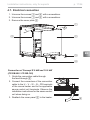
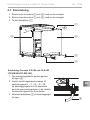
Installation instructions, only for experts p. 17/26
Connection of Concept R 9 kW and 10.5 kW
(CP-RB-090 / CP-RB-105)
1. Guide the connection cable through
the feed-through 6.
2. Connect the connectors of the connection
cable to the U – V – W – N – PE terminals
of the sauna heater and to the applicable
sauna control unit terminals. Observe the
installation instructions for the sauna control
unit when doing so.
3. Reattach the cover panel 2 to the heater.
4.7. Electrical connection
1. Unscrew the screws 3 and 4 with a screwdriver.
2. Unscrew the screws 1 and 5 with a screwdriver.
3. Remove the cover plate 2.
6
1
2
3
4
5

U1
V1
W1
N
U2
V2
W2
N
PE
PE
Installation instructions, only for experts p. 18/26
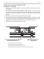
Connection of Concept R 12 kW and 15 kW
(CP-RB-120 / CP-RB-150)
1. Guide the connection cable for the sauna control unit through the feed-
through 8.
2. Connect the connectors of this connection cable to the U1 – V1 – W1 – N – PE
terminals on the connector block 9 and to the applicable sauna control unit
terminals. Observe the installation instructions for the sauna control unit when
doing so.
3. Guide the booster cable through the feed-through 7.
4. Connect the connectors of the booster cable to the U2 – V2 – W2 – N – PE
terminals on the connector block 6 and to the applicable booster terminals.
Observe the installation instructions of the booster when doing so.
5. Reattach the cover panel 2 to the heater.
6
7
9
8
6 Connector block for the booster
7 Feed-through for the booster cable
8 Connector block for the sauna control unit
9 Feed-through for the connection cable for the sauna control unit

EN
Instructions for use for the user p. 19/26
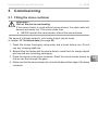
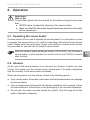
5. Commissioning
5.1. Filling the stone container
The amount of stones suited to your heater output can be found
in chapter 10. Technical data (see page 25).
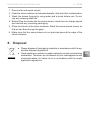
1. Wash the stones thoroughly using water and a brush before use. Do not
use any cleaning additives.
2. Beforellingtheheaterwiththesaunastones,checkthemforforeignobjects
and remove any remaining packaging.
3. Place the stones in the stone container. Stack the sauna stones loosely so
thataircanowthroughthegaps.
4. Make sure that the sauna stones do not protrude beyond the edge of the stone
container.
WARNING!
Risk of re due to overheating
If the sauna heater is used without sauna stones, the cabin walls will
becomeextremelyhot.Thiscouldcauseres.
●NEVER operate the sauna heater without the sauna stones.

Instructions for use for the user p. 20/26
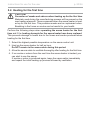
5.2. Heating for the rst time
CAUTION!
Formation of smoke and odours when heating up for the rst time
Materials used during the manufacturing process will be present on the
new heating elements. These evaporate when the sauna heater is heat-
edupforthersttime.Thisproducessmokeandanunpleasantodour.
Breathing in the fumes or smoke can be harmful to your health.
Perform the following steps when operating the sauna heater for the rst
time and if the heating elements for the sauna heater have been replaced.
This prevents damage to health due to the fumes and smoke produced when
heatingforthersttime.
1. Select the highest possible temperature on the sauna control unit.
2. Heat up the sauna heater for half an hour.
Do NOT remain in the sauna cabin during this period.
3. Allowthesaunacabintoventilatethoroughlyafterheatingforthersttime.
4. If no smoke or odours form the next time the sauna heater is heated, you
can start to use the sauna.
If smoke or odour is produced again, leave the sauna cabin immediately
and repeat the initial heating up process followed by ventilation.
Sidan laddas...
Sidan laddas...
Sidan laddas...
Sidan laddas...
Sidan laddas...
Sidan laddas...
Sidan laddas...
Sidan laddas...
Sidan laddas...
Sidan laddas...
Sidan laddas...
Sidan laddas...
Sidan laddas...
Sidan laddas...
Sidan laddas...
Sidan laddas...
Sidan laddas...
Sidan laddas...
Sidan laddas...
Sidan laddas...
Sidan laddas...
Sidan laddas...
Sidan laddas...
Sidan laddas...
Sidan laddas...
Sidan laddas...
Sidan laddas...
Sidan laddas...
Sidan laddas...
Sidan laddas...
Sidan laddas...
Sidan laddas...
Sidan laddas...
-
 1
1
-
 2
2
-
 3
3
-
 4
4
-
 5
5
-
 6
6
-
 7
7
-
 8
8
-
 9
9
-
 10
10
-
 11
11
-
 12
12
-
 13
13
-
 14
14
-
 15
15
-
 16
16
-
 17
17
-
 18
18
-
 19
19
-
 20
20
-
 21
21
-
 22
22
-
 23
23
-
 24
24
-
 25
25
-
 26
26
-
 27
27
-
 28
28
-
 29
29
-
 30
30
-
 31
31
-
 32
32
-
 33
33
-
 34
34
-
 35
35
-
 36
36
-
 37
37
-
 38
38
-
 39
39
-
 40
40
-
 41
41
-
 42
42
-
 43
43
-
 44
44
-
 45
45
-
 46
46
-
 47
47
-
 48
48
-
 49
49
-
 50
50
-
 51
51
-
 52
52
-
 53
53


Sentiotec CP-RB-090 Concept R Black Användarmanual
- Typ
- Användarmanual
på andra språk
Relaterade papper
-
Sentiotec Concept R combi Användarmanual
-
Sentiotec CP-RM-35 Concept R Mini Sauna Heater Användarmanual
-
-
-
-
-
-
-
-
Andra dokument
-
HARVIA sentiotec CP-RMC-35 Instructions For Installation And Use Manual
-
Tylö Sense Pure Användarmanual
-