
www.safeline-group.com
07.2023 © 2023 SafeLine and all the SafeLine products and
accessories are copyrighted by law.
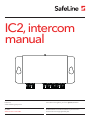
Intercom
SafeLine IC2 v.2.2.0 INT
IC2, intercom
manual
Innovation brought to you from Tyresö, Sweden

2SafeLine IC2 v.2.2.0 INT
This unit was built with state-
of-the-art technology and to
generally recognised safety
related technical standards
currently applicable. These
installation instructions are
to be followed by all people
working with the unit, in both
installation and maintenance.
It is extremely important that
these installation instructions
are made available at all times
to the relevant technicians,
engineers or servicing and
maintenance personnel. The
basis prerequisite for safe
handling and trouble free
operation of this system is a
sound knowledge of the basic
and special safety regulations
concerning conveyor techno-
logy, and elevators in particular.
The unit may only be used for
its intended purpose. Note in
particular that, no unauthorised
changes or additions may be
made inside the unit or indivi-
dual components.
Exclusion of liability
The manufacturer is not liable
with respect to the buyer of
this product or to third parties
for damage, loss, costs or work
incurred as a result of accidents,
misuse of the product, incorrect
installation or illegal changes,
repairs or additions. Claims
under warranty are likewise
excluded in such cases. The
technical data is the latest
available. The manufacturer
accepts no liability arising from
printing errors, mistakes or
changes.
Declaration of conformity
Download ”The declaration of
conformity” at our website:
www.safeline-group.com
Safety Precautions!
- Only trained professionals,
who are authorised to work on
the equipment, should install
and con gure this product.
- This quality product is dedi-
cated for the lift industry. It has
been designed and manufactu-
red to be used for its speci ed
purpose only. If it is to be used
for any other purpose, SafeLine
must be contacted in advance.
- It should not be modi ed
or altered in any way, and
should only be installed and
con gured strictly following the
procedures described in this
manual.
- All applicable health and
safety requirements and
equipment standards should be
considered and strictly adhered
to when installing and con -
guring this product.
- After installation and con -
guration this product and the
operation of the equipment
should be fully tested to ensure
correct operation before the
equipment is returned to
normal use.
Electrical and electronic
products may contain materials,
parts and units that can be
dangerous for the environment
and human health. Please
inform yourself about the local
rules and disposal collection
system for electrical and
electronic products. The correct
disposal of your old product
will help to prevent negative
consequences for the environ-
ment and human health.
General
information

3SafeLine IC2 v.2.2.0 INT
Content Fig. 1 - IC2 4
Fig. 2 - IC2-DIN 5
Fig. 3 - Installation: MX3+ / SL2 / SL6+ 6
Fig. 4 - Installation: MX2 / SL3000 8
Dansk 10
Tekniske data 11
Oversigt 11
Komponenter 11
Installation 11
Deutsch 12
Technische Daten 13
Einleitung 13
Komponenten 13
Installation 13
English 14
Technical data 15
Introduction 15
Components 15
Installation 15
Français 16
Données techniques 17
Introduction 17
Composants 17
Installation 17
Nederlands 18
Inleiding 19
Componenten 19
Installatie 19
Norsk 20
Tekniske data 21
Innledning 21
Komponenter 21
Installasjon 21
Suomi 22
Tekniset tiedot 23
Johdanto 23
Komponentit 23
Asennus 23
Svenska 24
Introduktion 25
Komponenter 25
Installation 25
Declaration of Conformity 27

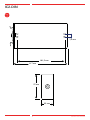
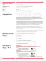
4
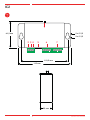
Fig.
1
1
2 3 4 5 6 7
61,2 mm
115 mm
2 x Ø 5,5
2 x Ø 9,5
101,5 mm
23 mm
SafeLine IC2 v.2.2.0 INT
IC2

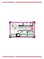
5
117 mm
101,5 mm
7,2 mm
23 mm
57 mm
Fig.
2
SafeLine IC2 v.2.2.0 INT
IC2-DIN

6
SL6+
A B C D E F
A
SL2
SafeLine SL2
www.safeline-group.com
A B
A
123
4 5 6
97 8
*0#
SafeLine MX3+
serial no.
hologram
sw ver.
www.safeline-group.com
MX3+
IC2
IC2
IC2
(-) 0 V
+ 12 V
+ 24 V
IC2
MX3+ / SL2 / SL6+
1
2
1
2
1
2
1
2
PSTN
Fig.
3
Installation: MX3+ / SL2 / SL6+
SafeLine IC2 v.2.2.0 INT

7
SL6+
A B C D E F
A
SL2
SafeLine SL2
www.safeline-group.com
A B
A
123
4 5 6
97 8
*0#
SafeLine MX3+
serial no.
hologram
sw ver.
www.safeline-group.com
MX3+
IC2
IC2
IC2
(-) 0 V
+ 12 V
+ 24 V
IC2
MX3+ / SL2 / SL6+
1
2
1
2
1
2
1
2
PSTN
SafeLine IC2 v.2.2.0 INT

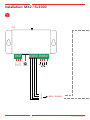
8
IC2
(-) 0 V
+ 12 V
+ 24 V
IC2
MX2 / SL3000
SafeLine MX2
123
4 5 6
97 8
*0#
www.safeline-group.com
MX2
SL3000
SafeLine MX2
123
4 5 6
97 8
*0#
www.safeline-group.com
1
2
3
4
1
2
3
4
IC2
1
2
3
4
PSTN
SafeLine IC2 v.2.2.0 INT
Fig.
4
Installation: MX2 / SL3000

9
IC2
(-) 0 V
+ 12 V
+ 24 V
IC2
MX2 / SL3000
SafeLine MX2
123
4 5 6
97 8
*0#
www.safeline-group.com
MX2
SL3000
SafeLine MX2
123
4 5 6
97 8
*0#
www.safeline-group.com
1
2
3
4
1
2
3
4
IC2
1
2
3
4
PSTN
SafeLine IC2 v.2.2.0 INT

DANSK

11
PSTNPSTN
PSTN
SafeLine IC2 v.2.2.0 INT
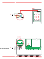
Oversigt For at aktivere samtaleanlægget skal du trykke på knappen i 1 sek.
Når begge lysdioder lyser, skal du løfte håndsættet fra telefonen.
Du hører 3 lange svartoner fra enheden, hvorefter du kan begynde
at kommunikere med elevatorstolen. Tryk på ”9” på tastaturet for at
afslutte et opkald, når du bruger en SafeLine 2000. Tryk på “#” for at
afslutte et opkald, når du bruger en SafeLine 3000, MX2 eller MX3.
En anden mulighed er at lægge telefonen på. Opkaldet afsluttes
derefter efter et tidsrum på højst 5 minutter.
Når ere SafeLine-nødtFig. 2 & 3)elefoner deler den samme
telefonlinje parallelt eller i en daisy-chain, vil enhederne have et
enhedsnummer programmeret. Når du tager håndsættet, efter at
begge lysdioder er tændt for kommunikation, skal du trykke på
enhedsnummeret på tastaturet på håndsættet for at kommunikere
med enheden. Når samtaleanlægget ikke er aktivt, er elevator-
telefonen forbundet til PSTN- eller GSM-netværket til udgående
telefonopkald eller nødopkald.
Hvis det kun er den grønne diode, der er tændt, er der mere end
15 V på 12 V-indgangen (til beskyttelse mod forkert tilslutning af 24
V).
1. Tryk på knappen for at aktivere samtaleanlægget
2. Strømforsyning (-) 0 Volt
3. + 12 Volt
4. + 24 Volt
5. RJ12 modulært stik. Maskinrumtelefon
6. Telefonlinje til SafeLine-telefon i elevatorstol
7. Telefonlinje
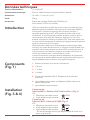
Komponenter
(Fig. 1)
Tekniske data
Strøm: 12 eller 24 VDC
Strømforbrug: 100 mA når tilsluttet, 0 mA i stand-by.
Størrelse: 18 x 60 x 111 mm (H x L x B)
Vægt: 200 g
Tilbehør: SafeLine IC2 DIN-monteringsplade (Fig. 2):
Til montering af IC2 på en DIN skinne
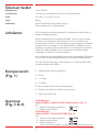
Installation
(Fig. 3 & 4)
Tilslut til:
SafeLine MX3+ / SafeLine SL2 / SafeLine SL6+ (Fig. 3)
IC2:
• PSTN tonevalgtelefon
• Indgående telefonlinje
Tilslut til:
SafeLine MX2 / SafeLine SL3000 (Fig. 4)
IC2:
• PSTN tonevalgtelefon
• Indgående telefonlinje
• Udgående telefonlinje
- Hvis telefonlinjen deles eller der anvendes en daisy-chain
forbindelse.

DEUTSCH

13
PSTNPSTN
PSTN
SafeLine IC2 v.2.2.0 INT
Einleitung
Komponenten
(Fig. 1)
Installation
(Fig. 3 & 4)
Mit SafeLine MX3+ / SafeLine SL2 / SafeLine SL6+ verbinden
(Fig. 3)
IC2:
• Standard-Tonwahltelefon
• Eingehende Telefonleitung
Mit SafeLine MX2 / SafeLine SL3000 verbinden (Fig. 4)
IC2:
• Standard-Tonwahltelefon
• Eingehende Telefonleitung
• Ausgehende Telefonleitung
- Bei gemeinsamer Verwendung der Telefonleitung und
Reihenschaltung
Technische Daten
Spannungsversorgung: 12 oder 24 VDC
Stromverbrauch: ca. 100 mA wenn aktiviert, 0 mA im Standby
Abmessungen: 18 x 60 x 111 mm (H x L x B)
Gewicht: 200 g
Zubehör: SafeLine IC2 DIN-Montageplatte(Fig. 2):
Zur Montage von IC2 auf einer DIN-Schiene
Um das Intercom zu aktivieren, drücken Sie die Taste 1 Sek.
lang. Wenn beide LEDs leuchten, heben Sie den Hörer ab. Es
besteht jetzt eine Verbindung zwischen der Aufzugskabine und
dem Maschinenraum. Drücken Sie „9“ auf der Tastatur, um eine
Verbindung zu beenden, wenn Sie ein SafeLine 2000 verwenden.
Drücken Sie „#“, um eine Verbindung zu trennen, wenn Sie ein
SafeLine 3000, SL1, MX2 oder MX3 verwenden. Sie können
auch einfach auegen. Die Verbindung wird nach maximal 5 min
getrennt.
Wenn das Intercom nicht in Gebrauch ist, wird das Aufzugstelefon
mit dem öffentlichen Telefonnetz verbunden und kann für ausge-
hende Anrufe oder Notrufe verwendet werden.
Wenn nur die grüne Diode leuchtet, liegen mehr als 15 V am
12-V-Eingang an (als Schutz gegen falsches Anschließen der
24-V-Stromversorgung).
1. Drucktaster zum Aktivieren des Intercoms.
2. (-) 0 Volt
3. + 12 Volt
4. + 24 Volt
5. RJ12-Modulstecker. Maschinenraum-Telefon
6. Telefonleitung zu SafeLine-Telefon in Aufzugkabine
7. Eingehende Telefonleitung

ENGLISH

15
PSTNPSTN
PSTN
SafeLine IC2 v.2.2.0 INT
Introduction
Components
(Fig. 1)
Installation
(Fig. 3 & 4)
Connect to:
SafeLine MX3+ / SafeLine SL2 / SafeLine SL6+ (Fig. 3)
IC2:
• PSTN tone dial telephone
• Incoming phone line
Connect to:
SafeLine MX2 / SafeLine SL3000 (Fig. 4)
IC2:
• PSTN tone dial telephone
• Incoming phone line
• Outgoing phone line
- If sharing phone line and using daisy-chain connection.
Technical data
Power: 12 or 24 VDC
Current consumption: 100 mA when connected, 0 mA in stand-by.
Size: 18 x 60 x 111 mm (H x L x W)
Weight: 200 g
Accessories: SafeLine IC2 DIN mounting plate (Fig. 2):
For mounting of IC2 on a DIN rail
To activate the intercom press the button for 1 sec. When both
LEDs are lit, lift the handset from the telephone. You will hear 3 long
answering tones from the unit and you can start communicating
with the lift cabin. Press ”9” on the keypad to end a call when using
a SafeLine 2000. Press “#” to end a call when using a SafeLine 3000,
MX2 or MX3. Another option is to put the phone on hook. The call
will then be terminated after an time out of maximum 5 minutes.
When several SafeLine emergency telephones are sharing the
same telephone line in parallel or a daisy chain the units will have
a unit number programmed. When you pick up the handset after
both LED’s are lit up for communication you will need to press
the unit number on the keypad of the handset for communication
to the unit. When the intercom is not active, the lift telephone is
connected to the PSTN- or GSM network for outgoing phone calls
or emergency calls.
If only the green diode is lit, there is more than 15V on the 12V
input (for protection agains connecting the 24V wrongly).
1. Push button to activate intercom
2. Power supply (-) 0 Volt
3. + 12 Volt
4. + 24 Volt
5. RJ12 Modular connector. Machine room telephone
6. Telephone line to Safeline telephone in lift car
7. Phone line

FRANÇAIS

17
PSTNPSTN
PSTN
SafeLine IC2 v.2.2.0 INT
Introduction
Composants
(Fig. 1)
Installation
(Fig. 3 & 4)
Connecter au :
SafeLine MX3+ / SafeLine SL2 / SafeLine SL6+ (Fig. 3)
IC2:
• Téléphone à tonalité normal
• Ligne téléphonique entrante
Connecter au :
SafeLine MX2 / SafeLine SL3000 (Fig. 4)
IC2:
• Téléphone à tonalité normal
• Ligne téléphonique entrante
• Ligne téléphonique sortante
- En cas de partage d’une ligne téléphonique et d’une conn-
exion en guirlande
L’IC2 est monté dans la salle des machines et connecté à la ligne
téléphonique et au téléphone d’urgence de l’ascenseur Safeline.
Pour activer l’interphone appuyez sur le bouton pendant 1
seconde, attendez que les 2 LED restent allumées, décrocher
le combiné. Il est maintenant possible de parler entre la cabine
de l’ascenseur et la salle dès machines. Appuyer sur « # » Pour
achever un appel en utilisant un Safeline SL2. Une autre option est
le raccrocher automatique du téléphone (L’appel sera alors achevé
après un maximum de 5 minutes).
Quand plusieurs téléphones SL2 partagent la même ligne télép-
honique, les unités devraient avoir un numéro d’unité. Quand vous
prenez le combiné après que les deux LED’S sont allumés pour la
communication vous devrez composer le numéro d’unité sur le
clavier du combiné pour communiquer à l’unité.
Lorsque l’interphone n’est pas utilisé le téléphone de l’ascenseur
sera connecté au réseau téléphonique et peut être utilisé pour les
appels téléphoniques sortants ou les appels d’urgence.
1. Pousser le bouton pour activer l’interphone.
2. (-) 0 Volt
3. + 12 Volt
4. + 24 Volt
5. Connecteur Modulaire RJ12. Téléphone de la salle des
machines
6. Ligne téléphonique reliée au téléphone Safeline dans une
cabine d’ascenseur
7. Ligne téléphonique entrante
Données techniques
Tension d’alimentation: 12 ou 24 VCC
Consommation électrique: Environ 100mA lorsque connecté, 0mA en attente.
Dimensions: 18 x 60 x 111 mm (H x L x P)
Poids: 200 g
Accessories: Platine de montage SafeLine IC2 DIN (Fig. 2):
Pour monter l’IC2 sur un rail DIN

NEDERLANDS

19
PSTNPSTN
PSTN
SafeLine IC2 v.2.2.0 INT
Componenten
(Fig. 1)
Installatie
(Fig. 3 & 4)
Op de SafeLine MX3+ / SafeLine SL2 / SafeLine SL6+ aanslu-
iten (Fig. 3)
IC2:
• Standaard telefoontoestel voor toonkiezen
• Inkomende telefoonkabel
Op de SafeLine MX2 / SafeLine SL3000 aansluiten (Fig. 4)
IC2:
• Standaard telefoontoestel voor toonkiezen
• Inkomende telefoonkabel
• Uitgaande telefoonkabel
- Bij een gedeelde telefoonlijn en het gebruik van een daisy-
chain aansluiting
Technische gegevens
Voedingsspanning: 12 or 24 VDC
Stroomverbruik: 100 mA wanneer deze is aangesloten. 0 mA in stand-by
Afmetingen: 18 x 60 x 111 mm (H x L x W)
Gewicht: 200 g
Toebehoren: SafeLine IC2 DIN montageplaat (Fig. 2):
Voor het monteren van de IC2 op een montagerail
Inleiding Druk de knop gedurende 1 sec in om de intercom te activeren.
Neem de telefoon van de haak, wanneer beide LED’s zijn verlicht.
Nu kan er tussen de liftcabine en de machinekamer een gesprek
plaatsvinden. Druk op “9” op het toetsenpaneel om een oproep
met gebruik van de SafeLine 2000 te beëindigen. De oproep zal
dan na max. Druk op “#” om een oproep te beëindigen, wanneer u
een SafeLine 3000, SL1, MX2 of MX3 gebruikt. Een andere optie is
om leg de telefoon op de haak. 5 min worden beëindigd.
Wanneer de intercom niet in gebruik is, zal de lifttelefoon op het
PSTN-netwerk zijn aangesloten. Deze kan dan worden gebruikt
voor uitgaande oproepen of noodoproepen.
Als alleen de groene diode is verlicht, staat er meer dan 15 V op de
12 V-ingang (als bescherming tegen het verkeerd aansluiten van
de 24 V).
1. Drukknop om de intercom te activeren.
2. (-) 0 Volt
3. + 12 Volt
4. + 24 Volt
5. RJ12-modulaire connector. Machinekamertelefoon
6. Telefoonlijn naar het SafeLine-toestel in de liftcabine
7. Phone line

NORSK
Sidan laddas...
Sidan laddas...
Sidan laddas...
Sidan laddas...
Sidan laddas...
Sidan laddas...
Sidan laddas...
Sidan laddas...
-
 1
1
-
 2
2
-
 3
3
-
 4
4
-
 5
5
-
 6
6
-
 7
7
-
 8
8
-
 9
9
-
 10
10
-
 11
11
-
 12
12
-
 13
13
-
 14
14
-
 15
15
-
 16
16
-
 17
17
-
 18
18
-
 19
19
-
 20
20
-
 21
21
-
 22
22
-
 23
23
-
 24
24
-
 25
25
-
 26
26
-
 27
27
-
 28
28


på andra språk
- Deutsch: Safeline iC2 Benutzerhandbuch
- français: Safeline iC2 Manuel utilisateur
- English: Safeline iC2 User manual
- dansk: Safeline iC2 Brugermanual
- Nederlands: Safeline iC2 Handleiding