Yamaha DRX-730 Bruksanvisning
- Kategori
- DVD-spelare
- Typ
- Bruksanvisning
Denna manual är också lämplig för

MICRO COMPONENT SYSTEM
DRX-730
OWNER'S MANUAL
MODE D'EMPLOI
BEDIENUNGSANLEITUNG
BRUKSANVISNING
MANUALE DI ISTRUZIONI
MANUAL DE INSTRUCCIONES
GEBRUIKSAANWIJZING
G

i
CAUTION
Use of controls or adjustments or performance of
procedures other than those specified herein may result in
hazardous radiation exposure.
AVERTISSEMENT
L’utilisation de commandes et l’emploi de réglages ou de
méthodes autres que ceux décrits ci-dessous, peuvent
entraîner une exposition à un rayonnement dangereux.
VORSICHT
Die Verwendung von Bedienelementen oder die
Einstellung bzw. die Ausführung von anderen als in dieser
Anleitung beschriebenen Vorgängen kann zu Gefährdung
durch gefährliche Strahlung führen.
OBSERVERA
Användning av reglage eller justeringar eller utförande av
åtgärder på annat sätt än så som beskrivs häri kan resultera i
farlig strålning.
ATTENZIONE
L’uso di controlli, regolazioni, operazioni o procedure non
specificati in questo manuale possono risultare in
esposizione a radiazioni pericolose.
PRECAUCIÓN
El uso de los controles, los ajustes o los procedimientos que
no se especifican enste manual pueden causar una
exposición peligrosa a la radiación.
LET OP
Gebruik van bedieningsorganen, instellingen of procedures
anders dan beschreven in dit document kan leiden tot
blootstelling aan gevaarlijke stralen.
ПРЕДОСТЕРЕЖЕНИЕ
Использование органов управления или выполнение
настроек или процедур, не указанных в данной
инструкции, может привести к воздействию опасного
излучения.
CAUTION VISIBLE AND / OR INVISIBLE LASER
RADIATION WHEN OPEN. AVOID EXPOSURE TO
BEAM.
VARNING
SYNLIG OCH / ELLER OSYNLIG
LASERSTRÅLNING NÄR DENNA DEL ÄR ÖPPNAD.
STRÅLEN ÄR FARLIG.
VARO ! AVATTAESSA OLET ALTTIINA NÄKYVÄLLE JA /
TAI NÄKYMÄTÖMÄLLE LASERSÄTEILYLLE. ÄLÄ KATSO
SÄTEESEEN.
VARNING SYNLIG OCH / ELLER OSYNLIG
LASERSTRÅLNING NÄR DENNA DEL ÄR ÖPPNAD.
BETRAKTA EJ STRÅLEN.
VORSICHT ! SICHTBARE UND / ODER UNSICHTBARE
LASERSTRAHLUNG WENN ABDECKUNG GEÖFFNET.
NICHT DEM STRAHL AUSSETZEN.
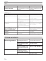
ATT ENTI ON RADIATION VISIBLE ET / OU INVISIBLE
LORSQUE L’APPAREIL EST OUVERT. EVITEZ TOUTE
EXPOSITION AU FAISCEAU.
ПРЕДУПРЕЖДЕНИЕ ПPИ OTKPЫTИИ УCTPOЙCTBA
BЫ MOЖETE ПОДBEPГHУTЬСЯ ВОЗДЕЙСТВИЮ
BИДИMOГO И/ИЛИ HEBИДИMOГO ЛAЗEPHOГO
ИЗЛУЧEHИЯ. ИЗБЕГAЙTE BOЗДЕЙСТВИЯ ЛУЧA.
Hyou2.fm i ページ 2008年8月27日 水曜日 午後3時27分

ii
En
English
VAROITUS
Muiden kuin tässä esitettyjen toimintojen säädön tai
asetusten muutto saattaa altistaa vaaralliselle säteilylle tai
muille vaarallisille toiminnoille.
DK
Advarsel: Usynlig laserstråling ved åbning når
sikkerhedsafbrydere er ude af funktion. Undgå utsættelse
for stråling.
Bemærk: Netafbryderen STANDBY/ON er sekundært
indkoblet og ofbryder ikke strømmen fra nettet. Den
indbyggede netdel er derfor tilsluttet til lysnettet så længe
netstikket sidder i stikkontakten.
N
Observer: Nettbryteren STANDBY/ON er sekundert
innkoplet. Den innebygdenetdelen er derfor ikke frakoplet
nettet så lenge apparatet er tilsluttet nettkontakten.
S
Klass 1 laseraparat
Varning! Om apparaten används på annat sätt än i denna
bruksanvisning specificerats, kan användaren utsättas för
osynlig laserstrålning, som överskrider gränsen för
laserklass 1.
Observera! Strömbrytaren STANDBY/ON är sekundärt
kopplad och inte bryter inte strömmen från nätet. Den
inbyggda nätdelen är därför ansluten till elnätet så länge
stickproppen sitter i vägguttaget.
SF
Luokan 1 laserlaite
Varoitus! Laitteen käyttäminen muulla kuin tässä
käyttöohjeessa mainitulla tavalla saattaa altistaa käyttäjän
turvallisuusluokan 1 ylittävälle näkymättömälle
lasersäteilylle.
Oikeus muutoksiin varataan. Laite ei saa olla alttiina tippu-
ja roiskevedelle.
Huom. Toiminnanvalitsin STANDBY/ON on kytketty
toisiopuolelle, eikä se kytke laitetta irti sähköverkosta.
Sisäänrakennettu verkko-osa on kytkettynä sähköverkkoon
aina silloin, kun pistoke on pistorasiassa.
VARO!
AVATTAESSA JA SUOJALUKITUS
OHITETTAESSA OLET ALTTIINA
NÄKYMÄTTÖMÄLLE LASERSÄTEILYLLE.
ÄLÄ KATSO SÄ TEESEEN.
VARNING!
OSYNLIG LASERSTRÅLNING NÄR DENNA DEL
ÄR ÖPPNAD OCH SPÄRREN ÄR URKOPPLAD.
BETRAKTA EJ STRÅLEN.
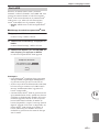
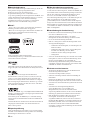
Information for Users on Collection and Disposal of Old Equipment and
used Batteries
These symbols on the products, packaging, and/or accompanying documents mean that used electrical and
electronic products and batteries should not be mixed with general household waste. For proper treatment,
recovery and recycling of old products and used batteries, please take them to applicable collection points, in
accordance with your national legislation and the Directives 2002/96/EC and 2006/66/EC.
By disposing of these products and batteries correctly, you will help to save valuable resources and prevent any
potential negative effects on human health and the environment which could otherwise arise from
inappropriate waste handling.
For more information about collection and recycling of old products and batteries, please contact your local
municipality, your waste disposal service or the point of sale where you purchased the items.
[Information on Disposal in other Countries outside the European Union]
These symbols are only valid in the European Union. If you wish to discard these items, please contact your local
authorities or dealer and ask for the correct method of disposal.
Note for the battery symbol (bottom two symbol examples):
This symbol might be used in combination with a chemical symbol. In this case it complies with the
requirement set by the Directive for the chemical involved.

iii
En
1.
To assure the finest performance, please read this manual
carefully. Keep it in a safe place for future reference.
2.
Install this sound system in a well ventilated, cool, dry, clean
place – away from direct sunlight, heat sources, vibration,
dust, moisture, and/or cold. Allow ventilation space of at
least 10 cm on the top, 10 cm on the left and right, and 10 cm
on the back of this unit.
3.
Locate this unit away from other electrical appliances,
motors, or transformers to avoid humming sounds.
4.
Do not expose this unit to sudden temperature changes
from cold to hot, and do not locate this unit in an
environment with high humidity (i.e., a room with a
humidifier) to prevent condensation inside this unit, which
may cause an electrical shock, fire, damage to this unit,
and/or personal injury.
5.
Avoid installing this unit where foreign objects may fall onto
this unit and/or this unit may be exposed to liquid dripping
or splashing. On the top of this unit, do not place:
—Other components, as they may cause damage and/or
discoloration on the surface of this unit.
—Burning objects (i.e., candles), as they may cause fire,
damage to this unit, and/or personal injury.
—Containers with liquid in them, as they may fall and
liquid may cause electrical shock to the user and/or
damage to this unit.
6.
Do not cover this unit with a newspaper, tablecloth, curtain,
etc., in order not to obstruct heat radiation. If the
temperature inside this unit rises, it may cause fire, damage
to this unit, and/or personal injury.
7.
Do not plug in this unit to a wall outlet until all connections
are complete.
8.
Do not operate this unit upside-down. It may overheat,
possibly causing damage.
9.
Do not use force on switches, knobs and/or cords.
10.
When disconnecting the power cable from the wall outlet,
grasp the plug; do not pull the cable.
11.
Do not clean this unit with chemical solvents; this might
damage the finish.
12.
Only voltage specified on this unit must be used. Using this
unit with a higher voltage than specified is dangerous and
may cause fire, damage to this unit, and/or personal injury.
Ya m a ha will not be held responsible for any damage
resulting from use of this unit with a voltage other than
specified.
13.
To prevent damage by lightning, keep the power cord
disconnected from a wall outlet or the unit during a
lightning storm.
14.
Do not attempt to modify or fix this unit. Contact qualified
Ya m a ha service personnel when any service is needed. The
cabinet should never be opened for any reasons.
15.
When not planning to use this unit for long periods of time
(i.e., vacation), disconnect the AC power plug from the wall
outlet.
16.
Install this unit near the AC outlet and where the AC power
plug can be reached easily.
17.
Be sure to read the “Troubleshooting” section in the owner’s
manual on common operating errors before concluding that
this unit is faulty.
18.
Before moving this unit, press STANDBY/ON to set the unit
in standby mode, then disconnect the AC power plug from
the AC wall outlet.
19.
The batteries shall not be exposed to excessive heat such as
sunshine, fire or like.
20.
Excessive sound pressure from earphones and headphones
can cause hearing loss.
■
DANGER
This unit emits visible laser radiation when open. Avoid direct
eye exposure to beam. When this unit is plugged into the wall
outlet, do not place your eyes close to the opening of the disc
tray and other openings to look into inside.
■
LASER SAFETY
This unit employs a laser. Due to possible eye injury, only a
qualified service person should remove the cover or attempt to
service this device.
Caution: Read this before operating your unit.
This unit is not disconnected from the AC power source as
long as it is connected to the wall outlet, even if this unit itself
is turned off. This state is called the standby mode. In this
state, this unit is designed to consume a very small quantity of
power.
The laser component in this product is capable of emitting
radiation exceeding the limit for Class 1.
LASER
Type Semiconductor laser AlGaInP
Wave length 655 nm (DVD)
790 nm (VCD/CD)
Output Power 5 mW (DVD)
7 mW (VCD/CD)
Beam divergence 20 degree
WARNING
TO REDUCE THE RISK OF FIRE OR ELECTRIC SHOCK,
DO NOT EXPOSE THIS APPLIANCE TO RAIN OR
MOISTURE.
CAUTION
Danger of explosion if battery is incorrectly replaced.
Replace only with the same or equivalent type.

iv
En
English
■
For U.K. customers
If the socket outlets in the home are not suitable for the plug
supplied with this appliance, it should be cut off and an
appropriate 3 pin plug fitted. For details, refer to the
instructions described below.
Note:
The plug severed from the mains lead must be destroyed, as a
plug with bared flexible cord is hazardous if engaged in a live
socket outlet.
■
Special Instructions for U.K. Model
■
Handling the remote control
•The area between the remote control and this unit must be
clear of large obstacles.
•Do not spill water or other liquids on the remote control.
•Do not drop the remote control.
•Do not leave or store the remote control in the following
types of conditions:
—places of high humidity, such as near a bath
—places of high temperature, such as near a heater or a stove
—places of extremely low temperatures
—dusty places
•Do not expose the remote control sensor to strong lighting,
in particular, an inverter type fluorescent lamp; otherwise,
the remote control may not work properly. If necessary,
position this unit away from direct lighting.
■
Notes on batteries
•Change all of the batteries if you notice that the operation
range of the remote control decreases.
•Use AA, R6, UM-3 batteries.
•Make sure that the polarities are correct. See the illustration
inside the battery compartment.
•Remove the batteries if the remote control is not used for an
extended period of time.
•Do not use old batteries together with new ones.
•Do not use different types of batteries (such as alkaline and
manganese batteries) together. Read the packaging carefully
as these different types of batteries may have the same shape
and color.
•If the batteries have leaked, dispose of them immediately.
Avoid touching the leaked material or letting it come into
contact with clothing, etc. Clean the battery compartment
thoroughly before installing new batteries.
•Do not throw away batteries with general house waste;
dispose of them correctly in accordance with your local
regulations.
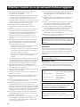
Limited Guarantee for European Economic Area (EEA) and Switzerland
Thank you for having chosen a Yamaha product. In the unlikely event that your Yamaha product needs guarantee service, please contact the dealer from
whom it was purchased. If you experience any difficulty, please contact Yamaha representative office in your country. You can find full details on our
website (
http://www.yamaha-hifi.com/
or
http://www.yamaha-uk.com/
for U.K. resident).
The product is guaranteed to be free from defects in workmanship or materials for a period of two years from the date of the original purchase. Yamaha
undertakes, subject to the conditions listed below, to have the faulty product or any part(s) repaired, or replaced at Yamaha’s discretion, without any
charge for parts or labour. Yamaha reserves the right to replace a product with that of a similar kind and/or value and condition, where a model has been
discontinued or is considered uneconomic to repair.
Conditions
1. The original invoice or sales receipt (showing date of purchase, product code and dealer’s name) MUST accompany the defective product, along
with a statement detailing the fault. In the absence of this clear proof of purchase, Yamaha reserves the right to refuse to provide free of charge
service and the product may be returned at the customer’s expense.
2. The product MUST have been purchased from an AUTHORISED Yamaha dealer within the European Economic Area (EEA) or Switzerland.
3. The product must not have been the subject of any modifications or alterations, unless authorised in writing by Yamaha.
4. The following are excluded from this guarantee:
a. Periodic maintenance and repair or replacement of parts due to normal wear and tear.
b. Damage resulting from:
(1) Repairs performed by the customer himself or by an unauthorised third party.
(2) Inadequate packaging or mishandling, when the product is in transit from the customer. Please note that it is the customer’s responsibility to
ensure the product is adequately packaged when returning the product for repair.
(3) Misuse, including but not limited to (a) failure to use the product for its normal purpose or in accordance with Yamaha’s instructions on the
proper use, maintenance and storage, and (b) installation or use of the product in a manner inconsistent with the technical or safety standards
in force in the country where it is used.
(4) Accidents, lightning, water, fire, improper ventilation, battery leakage or any cause beyond Yamaha’s control.
(5) Defects of the system into which this product is incorporated and/or incompatibility with third party products.
(6) Use of a product imported into the EEA and/or Switzerland, not by Yamaha, where that product does not conform to the technical or safety
standards of the country of use and/or to the standard specification of a product sold by Yamaha in the EEA and/or Switzerland.
(7) Non AV (Audio Visual) related products.
(Products subject to “Yamaha AV Guarantee Statement” are defined in our website at
http://www.yamaha-hifi.com/
or
http://www.yamaha-uk.com/
for U.K. resident.)
5. Where the guarantee differs between the country of purchase and the country of use of the product, the guarantee of the country of use shall apply.
6. Yamaha may not be held responsible for any losses or damages, whether direct, consequential or otherwise, save for the repair or replacement of the
product.
7. Please backup any custom settings or data, as Yamaha may not be held responsible for any alteration or loss to such settings or data.
8. This guarantee does not affect the consumer’s statutory rights under applicable national laws in force or the consumer’s rights against the dealer
arising from their sales/purchase contract.
IMPORTANT
THE WIRES IN MAINS LEAD ARE COLOURED IN
ACCORDANCE WITH THE FOLLOWING CODE:
Blue: NEUTRAL
Brown: LIVE
As the colours of the wires in the mains lead of this
apparatus may not correspond with the coloured markings
identifying the terminals in your plug, proceed as follows:
The wire which is coloured BLUE must be connected to the
terminal which is marked with the letter N or coloured
BLACK. The wire which is coloured BROWN must be
connected to the terminal which is marked with the letter L
or coloured RED.
Making sure that neither core is connected to the earth
terminal of the three pin plug.

v
En
■
Legal notices
This product incorporates copyright protection
technology that is protected by U.S. patents and other
intellectual property rights. Use of this copyright
protection technology must be authorized by
Macrovision, and is intended for home and other
limited viewing uses only unless otherwise
authorized by Macrovision. Reverse engineering or
disassembly is prohibited.
■
iPod™
“Ap p l e ,” “ i P o d ,” and “iTunes” are trademarks of Apple Inc.,
registered in the U.S. and other countries.
Bluetooth is a registered trademark of Bluetooth SIG and is
used by Yamaha in accordance with a license agreement.
DivX, DivX Ultra Certified, and associated logos are
trademarks of DivX, Inc. and are used under license.
Manufactured under license from Dolby Laboratories. Dolby
and the double-D symbol are trademarks of Dolby
Laboratories.
Manufactured under license under U.S. Patent #’s: 5,451,942;
5,956,674; 5,974,380; 5,978,762; 6,487,535 & other U.S. and
worldwide patents issued & pending. DTS and DTS 2.0 +
Digital Out are registered trademarks and the DTS logos and
Symbol are trademarks of DTS, Inc. © 1996-2007 DTS, Inc. All
Rights Reserved.
“HDMI”, the “HDMI” logo, and “High-Definition Multimedia
Interface” are trademarks or registered trademarks of HDMI
Licensing LLC.
MPEG Layer-3 audio decoding technology licensed from
Fraunhofer IIS and Thomson multimedia.
Windows Media is either a registered trademark or trademark
of Microsoft Corporation in the United States and/or other
countries.
■
Memory backup
If the power cable is disconnected from the AC wall
outlet, the DRX-730 will save the radio presets and
other settings for at least 1 week.
■
About this manual
Unless otherwise stated, instructions in this manual
such as “press ENTER” refer to the buttons on the
remote control.
Instructions and procedures in this manual assume
that the DRX-730 is already turned on.
This manual was printed before the DRX-730 went
into production. Under our policy of continuous
improvement, design and specifications are subject to
change. In the unlikely event that an explanation in
this owner’s manual disagrees with the actual
operation on the DRX-730, the DRX-730 is to be
taken as correct.

1
En
English
1
2
3
4
5
6
7
8
9
10
Appendix
1 Introduction . . . . . . . . . . . . . . . . . . . . 2
Features . . . . . . . . . . . . . . . . . . . . . . . . . . . . . . . . . 2
Supplied accessories . . . . . . . . . . . . . . . . . . . . . 2
Front panel . . . . . . . . . . . . . . . . . . . . . . . . . . . . . . 3
Display . . . . . . . . . . . . . . . . . . . . . . . . . . . . . . . . . . 4
Rear panel . . . . . . . . . . . . . . . . . . . . . . . . . . . . . . . 5
Remote control . . . . . . . . . . . . . . . . . . . . . . . . . . 6
2 Getting Started . . . . . . . . . . . . . . . . . 8
Installing batteries in the remote control . . 8
Connecting speakers . . . . . . . . . . . . . . . . . . . . . 9
Connecting a powered subwoofer . . . . . . . 10
Connecting antennas . . . . . . . . . . . . . . . . . . . 11
Connecting a TV . . . . . . . . . . . . . . . . . . . . . . . . 12
Connecting a recorder (CDR, MDR, etc.) . . 14
Connecting an AV receiver or decoder . . . 15
Connecting the power cable . . . . . . . . . . . . 15
3 General Functions . . . . . . . . . . . . . . 16
Turning on the DRX-730 . . . . . . . . . . . . . . . . . 16
Selecting input sources . . . . . . . . . . . . . . . . . 16
Adjusting the volume . . . . . . . . . . . . . . . . . . . 17
Muting the sound . . . . . . . . . . . . . . . . . . . . . . . 17
Adjusting the bass and treble . . . . . . . . . . . 18
Adjusting the balance . . . . . . . . . . . . . . . . . . . 18
Pure Direct playback mode . . . . . . . . . . . . . . 19
Using headphones . . . . . . . . . . . . . . . . . . . . . . 19
Adjusting the display brightness . . . . . . . . 20
Using the sleep timer . . . . . . . . . . . . . . . . . . . 20
Setting the clock . . . . . . . . . . . . . . . . . . . . . . . . 21
Viewing the time . . . . . . . . . . . . . . . . . . . . . . . . 22
Auto standby . . . . . . . . . . . . . . . . . . . . . . . . . . . 22
4 Playing Discs . . . . . . . . . . . . . . . . . . . 23
Using the on-screen display . . . . . . . . . . . . . 23
Playing discs . . . . . . . . . . . . . . . . . . . . . . . . . . . . 23
Slow-motion playback . . . . . . . . . . . . . . . . . . 26
Frame-by-frame playback . . . . . . . . . . . . . . . 26
Selecting languages and audio . . . . . . . . . . 27
Selecting subtitles . . . . . . . . . . . . . . . . . . . . . . 27
Selecting camera angles . . . . . . . . . . . . . . . . 28
Zoom . . . . . . . . . . . . . . . . . . . . . . . . . . . . . . . . . . . 28
Repeat playback . . . . . . . . . . . . . . . . . . . . . . . . 29
A–B repeat playback . . . . . . . . . . . . . . . . . . . . 29
Random playback . . . . . . . . . . . . . . . . . . . . . . . 30
Program playback . . . . . . . . . . . . . . . . . . . . . . 31
Searching Discs . . . . . . . . . . . . . . . . . . . . . . . . . 32
Playing JPEG slideshows . . . . . . . . . . . . . . . . 33
Using Disc Navigator with DVD-Video,
VCD, and SVCD discs . . . . . . . . . . . . . . . . . 34
Using Disc Navigator with MP3, WMA,
MPEG-4 AAC, DivX®, WMV, and JPEG
discs . . . . . . . . . . . . . . . . . . . . . . . . . . . . . . . . .35
Viewing disc information . . . . . . . . . . . . . . . .36
Viewing the audio format . . . . . . . . . . . . . . . .36
5 Using the Tuner . . . . . . . . . . . . . . . . 37
Tuning in to radio stations . . . . . . . . . . . . . . .37
Using presets . . . . . . . . . . . . . . . . . . . . . . . . . . . .39
Radio Data System (Europe and Russia
models only) . . . . . . . . . . . . . . . . . . . . . . . . .40
6 Using the Timer . . . . . . . . . . . . . . . . 44
Setting the input source . . . . . . . . . . . . . . . . .44
Setting the on time . . . . . . . . . . . . . . . . . . . . . .45
Setting the off time . . . . . . . . . . . . . . . . . . . . . .45
Turning the timer on and off . . . . . . . . . . . . .46
7 Portable Device Playback . . . . . . . 47
Music player playback . . . . . . . . . . . . . . . . . . .47
iPod playback . . . . . . . . . . . . . . . . . . . . . . . . . . .47
USB playback . . . . . . . . . . . . . . . . . . . . . . . . . . . .49
Bluetooth playback . . . . . . . . . . . . . . . . . . . . . .51
8 Recording . . . . . . . . . . . . . . . . . . . . . 53
9
Audio Settings and Video Adjust
. . 54
Audio Settings menu . . . . . . . . . . . . . . . . . . . .54
Video Adjust menu . . . . . . . . . . . . . . . . . . . . . .55
10Initial Settings . . . . . . . . . . . . . . . . . 56
Initial Settings menu . . . . . . . . . . . . . . . . . . . .56
Appendix . . . . . . . . . . . . . . . . . . . . . . . . . 61
Supported discs and formats . . . . . . . . . . . .61
Looking after discs . . . . . . . . . . . . . . . . . . . . . .64
Looking after the DRX-730 . . . . . . . . . . . . . . .65
Resetting the DRX-730 . . . . . . . . . . . . . . . . . . .65
Language, country, and region lists . . . . . .66
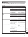
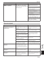
Troubleshooting . . . . . . . . . . . . . . . . . . . . . . . .67
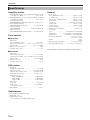
Specifications . . . . . . . . . . . . . . . . . . . . . . . . . . .74
Contents

2
En
Thank your for choosing the Yamaha DRX-730 DVD
Receiver. To get the most enjoyment from your new
Yamaha pro duct, please read this manual carefully,
and keep it in a safe place for future reference.
•Play the following discs: DVD-Video, DVD-VR
(DVD-R/RW/R DL discs recorded in VR mode),
VCD, SVCD, Audio CD, DTS CD
•Play the following files: MP3, WMA, MPEG-4
AAC, JPEG, WMV
1
•Official DivX
®
Ultra Certified product.
•Plays all versions of DivX
®
video (including
DivX
®
6) with enhanced playback of DivX
®
media files and the DivX
®
Media Format.
•HDMI output (1080p upscaling)
• FM/AM tuner with 40 presets
•Radio Data System (Europe and Russia models)
• D-class amp: 30 W x 2 channels into 6Ω
•Pure Direct high-fidelity playback mode
•Front panel mini jack for quick and easy playback
from portable music players.
•Front panel USB port for quick and easy playback
from USB storage devices.
•DOCK jack for connecting an optional Yamaha
iPod universal dock allows you to listen to your
iPod music in high quality. And, you can control
your iPod with the DRX-730’s remote control and
recharge it while enjoying your music.
•The DOCK jack can also be used to connect a
Ya m a h a YBA-10 Bluetooth Wireless Audio
Receiver so you can listen to the music stored on
your Bluetooth-compatible music player or
mobile phone in high quality. And you can
control your Bluetooth device with the DRX-730’s
remote control.
•Timer function
•On-screen display (OSD)
•Full-function remote control
• SCART AV jack with RGB (Europe and Russia
models)
•Optical digital output
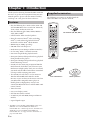
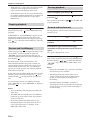
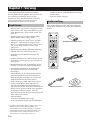
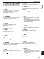
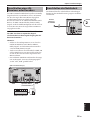
The following accessories are included with the
DRX-730. Make sure you have them all.
Chapter 1: Introduction
Features
1. The DRX-730 can play MP3, WMA, MPEG-4 AAC, and
JPEG files stored on CD-R/RW, DVD-R/RW, and
DVD+R/RW discs or USB storage devices, and DivX
®
and
WMV files stored on CD-R/RW, DVD-R/RW, and
DVD+R/RW discs. See “Supported discs and formats” on
page 61 for full details.
Supplied accessories
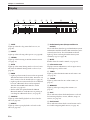
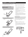
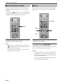
1
STANDBY/ON
ZOOM
OPEN/CLOSE
ON SCREEN
423
586
90
7
VOLUME
TIMER SLEEP
MUTE
DOCK
TUNER
MEMORY
SOUND
DVD/USB
PURE DIRECT
AUX/PORTABLE
DISPLAY
DIMMER
AUDIO
SUBTITLE
PLAY MODE
ANGLE
CLEAR
BLUETOOTH
PTY SEEK
ON
MODE START
FREQ/TEXT
OFF
PRESET
MENU
INFO.
TOP MENU
SETUP
RETURN
AEAE
ENTER
BAND
AUTO/
MANUAL
Remote control
Two batteries (AA, R06, UM-3)
Video pin cable
Indoor FM antenna
AM loop antenna

Chapter 1: Introduction
3
En
English
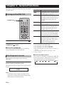
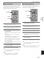
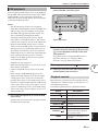
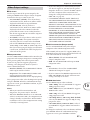
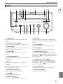
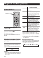
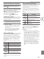
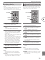
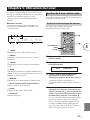
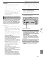
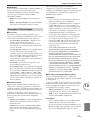
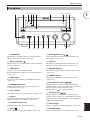
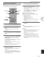
A
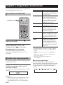
STANDBY/ON
Sets the DRX-730 to on or standby (see page 16).
B
Open/Close ( )
Opens and closes the disc tray (see page 23).
C
TIMER LED
Lights up when the DRX-730 on standby and the
timer is on (see page 46).
D
HDMI LED
Lights up when the HDMI OUT is used (see page 57).
E
PROGRESSIVE LED
Lights up when progressive video is being output (see
page 57).
F
Disc tray
Used to load discs (see page 23).
G
Display
Displays various information. See “Display” on page 4
for more details.
H
Remote control sensor
Receives signals from the remote control.
I
Stop ( )
Stops playback (see page 24).
J
Play/Pause ( / )
Starts and pauses playback (see page 23).
K
USB port
Used to connect a USB storage device containing
music or picture files (see page 49).
L
PORTABLE jack
Used to connect a portable music player (see
page 47).
M
PHONES jack
Used to connect headphones (see page 19).
N Previous/Rewind ( / )
Selects earlier tracks or chapters (see page 25). Works
the same as the Rewind ( ) button on the remote
control when held down.
O Next/Fast Forward ( / )
Selects subsequent tracks or chapters (see page 25).
Works the same as the Fast Forward ( ) button on
the remote control when held down.
P INPUT control
Selects input sources (see page 16).
Q VOLUME control
Adjusts the volume (see page 17).
Front panel
STANDBY/ON
USB PORTABLE PHONES
INPUT
VOLUME
TIMER
HDMI
PROGRESSIVE
B
KLMNO P Q
9J6345 871
1

Chapter 1: Introduction
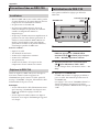
4 En
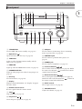
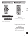
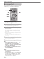
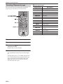
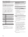
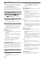
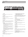
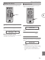
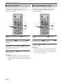
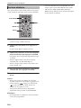
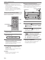
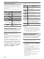
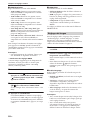
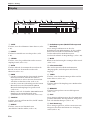
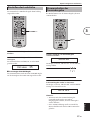
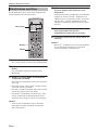
A SLEEP
Lights up when the sleep timer has been set (see
page 20).
B PRESET
Lights up when selecting radio presets (see page 40).
C STEREO
Lights up when listening to an FM station in stereo
(see page 37).
D AUTO
Lights up when Auto Tuning mode is selected. Goes
off when the Manual Tuning mode is selected (see
page 37).
E DOCK
•Lights up when an iPod is inserted in an optional
Ya maha iPod universal dock (YDS-10 or YDS-11)
that’s connected to the DOCK jack (see page 47).
•Lights up when a connection has been established
between a Bluetooth device and an optional
Ya m a h a YBA-10 Bluetooth Wireless Audio
Receiver (see page 51).
•Flashes while the optional Yamaha YBA-10
Bluetooth Wireless Audio Receiver is pairing or
searching for a Bluetooth device (see page 51).
F SHUFFLE
Lights up when shuffle playback is selected on the
iPod (see page 48).
G REPEAT
Lights up when repeat playback is selected on the
iPod (see page 48).
H Radio Data System (Europe and Russia
models)
These indicators show the types of Radio Data System
information available from the FM station that you’re
currently tuned in to. The PTY HOLD indicator
lights up when searching for Radio Data System
stations by type (see page 40).
I MUTE
Flashes when the sound is muted (see page 17).
J Information area
Displays various information, such as input source,
radio frequency, and the time.
K TIMER
Lights up when the DRX-730 is on and timer is on
(see page 46).
L TUNED
Lights up when tuned in to a radio station (see
page 37).
M MEMORY
Lights up when presetting radio stations (see
page 39).
N iPod
These indicators show which iPod menu is selected
for browsing: Playlists, Artists, Albums, Songs, or
Genres (see page 48).
O iPod control
These indicators show which cursor buttons can be
used while navigating iPod menus (see page 48).
Display
GENRES
SONGS
ALBUMS
ARTISTSPLAYLISTS
MEMORY
TUNED
TIMER
SLEEP
STEREO
AUTO
DOCK MUTE
SHUFFLE
REPEAT
PS
PTY RT CT PTY
HOLD
PRESET
A BC E IDFGH
KLM N
O
J

Chapter 1: Introduction
5 En
English
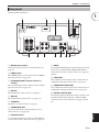
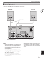
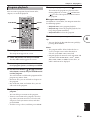
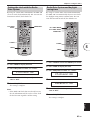
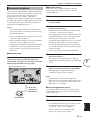
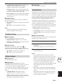
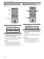
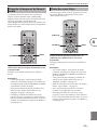
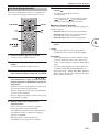
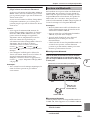
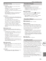
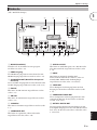
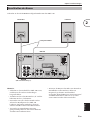
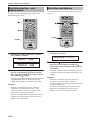
(Europe model shown here.)
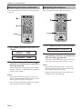
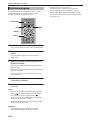
A MAINS (power cable)
Connect the power cable to an AC wall outlet (see
page 15).
B HDMI output
This HDMI output can be connected to an HDMI
input on your TV (see page 13).
C AV MONITOR OUT (Europe and Russia
models)
This SCART output can be connected to a SCART
input on your TV (see page 14).
D FM ANT
The FM antenna connects here (see page 11).
E AM ANT
The AM antenna connects here (see page 11).
F SPEAKERS
Speakers are connected here (see page 9).
G SUBWOOFER OUT
A powered subwoofer (sold separately) can be
connected here (see page 10).
H AUX IN and OUT
A recording component, such as a CDR, MDR, or
cassette deck, can be connected here (see page 14).
I DOCK
An optional Yamaha iPod universal dock (YDS-10 or
YDS-11) or a Yamaha YBA-10 Bluetooth Wireless
Audio Receiver can be connected here (see pages 47
and 51).
J VIDEO OUT
This composite video output can be connected to a
composite video input on your TV (see page 12).
K COMPONENT VIDEO OUT
This component video output can be connected to a
component video input on your TV (see page 12).
L OPTICAL DIGITAL OUT
This optical digital audio output can be connected to
an optical digital audio input on a CDR or MDR
recorder or AV receiver/decoder (see pages 14 and
15).
Rear panel
HDMI
MAINS
AM
ANT
ANT
GND
FM
UNBAL.
75
OUT
OPTICAL
VIDEO
OUT IN
MIN
COMPONENT
DIGITALDOCK
AV MONITOR OUT
AUX
OUT
SUBWOOFER
SPEAKERS VIDEO OUT
P
Y
R
P
B
R
R
SPEAKER
6
1 B 3 4 5
6 7 8 9 J K L
1

Chapter 1: Introduction
6 En
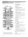
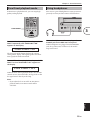
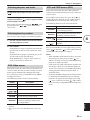
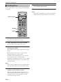
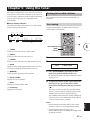
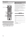
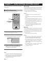
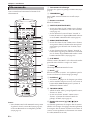
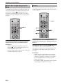
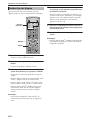
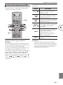
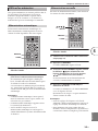
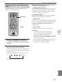
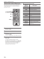
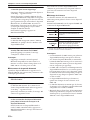
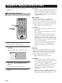
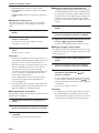
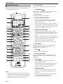
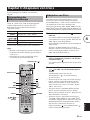
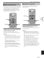
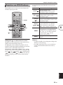
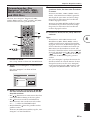
This section provides a brief description of the remote
control’s buttons.
Tip:
•In addition to controlling the DRX-730, the
remote control can also be used to control
playback on an iPod (see page 47) or a Bluetooth
music player or mobile phone (see page 51).
A Infrared transmitter
Transmits control signals to the DRX-730 (see
page 8).
B STANDBY/ON ( )
Sets the DRX-730 to on or standby (see page 16).
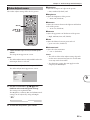
C Number buttons
Enter numbers.
D SUBTITLE (BLUETOOTH OFF)
•When the input source is DVD, selects subtitles
on DVDs (see page 27).
•When the input source is DOCK, disconnects
from the currently connected Bluetooth device
and makes the DRX-730 non-discoverable (see
page 51).
E AUDIO (BLUETOOTH ON)
•When the input source is DVD, selects audio
formats and foreign-language soundtracks on
DVDs (see page 27).
•When the input source is DOCK, initiates pairing
or establishes a connection with the last used
Bluetooth device and makes the DRX-730
discoverable (see page 51).
F PLAY MODE
Displays the Play Mode menu on the connected TV
when the input source is DVD.
G Pause ( )
Pauses playback.
H Rewind ( )
Rewinds playback. Also used for slow-motion
playback and frame-by-frame playback.
I Previous ( )
•Selects earlier tracks or chapters.
•On Europe and Russia models, it also works as the
Radio Data System PTY SEEK MODE button.
J TOP MENU (INFO.)
•When the input source is DVD, displays the
DVD’s top menu.
•When the input source is DOCK, selects the iPod
control mode (see page 47).
K Cursor buttons ( )/( )/( )/( ) and ENTER
Used to navigate on-screen menus and change
settings. Also used to navigate iPod menus. The
cursor buttons are also used for radio tuning and
selecting presets.
L SETUP
Displays the Setup menu on the connected TV when
the input source is DVD.
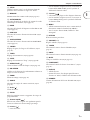
Remote control
1
STANDBY/ON
ZOOM
OPEN/CLOSE
ON SCREEN
423
586
90
7
VOLUME
TIMER SLEEP
MUTE
DOCK
TUNER
MEMORY
SOUND
DVD/USB
PURE DIRECT
AUX/PORTABLE
DISPLAY
DIMMER
AUDIO
SUBTITLE
PLAY MODE
ANGLE
CLEAR
BLUETOOTH
PTY SEEK
ON
MODE START
FREQ/TEXT
OFF
PRESET
MENU
INFO.
TOP MENU
SETUP
RETURN
AEAE
ENTER
BAND
AUTO/
MANUAL
1
B
5
4
7
M
6
8
9
J
L
N
O
P
R
S
T
Q
l
g
j
U
V
W
X
Y
b
Z
a
c
d
e
f
i
h
k
3
K

Chapter 1: Introduction
7 En
English
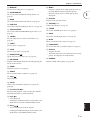
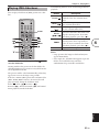
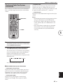
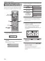
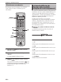
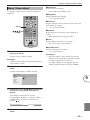
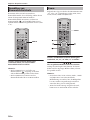
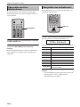
M MEMORY
Used to store radio presets (see page 39).
N AUTO/MANUAL
Selects the Auto and Manual Tuning modes (see
page 37).
O BAND
Selects the FM and AM radio bands (see page 37).
P DVD/USB
Selects the DVD and USB input sources (see page 16).
Q AUX/PORTABLE
Selects the AUX and PORTABLE input sources (see
page 16).
R SOUND
Used to adjust the bass, treble, and balance (see
page 18).
S TIMER
Sets the timer (see page 44).
T SLEEP
Sets the sleep timer (see page 20).
U OPEN/CLOSE ( )
Opens and closes the disc tray (see page 23).
V ON SCREEN
Displays information about the currently playing disc
on the connected TV.
W ZOOM
Zooms the picture (see page 28).
X ANGLE
Selects camera angles on DVDs (see page 28).
Y Stop ( )
Stops playback.
Z CLEAR
Clears entered numbers and deletes steps in the
program.
a Fast forward ( )
Fast forwards playback. Also used for slow-motion
playback and frame-by-frame playback.
b Play ( )
•Starts playback.
•On Europe and Russia models, it also works as the
Radio Data System PTY SEEK START button.
c Next ( )
•Selects subsequent tracks or chapters.
•On Europe and Russia models, it also works as the
Radio Data System FREQ/TEXT button.
d MENU
•Displays a DVD’s menu. (May work the same as
the TOP MENU button with some DVDs.)
•When the input source is USB, displays Disc
Navigator.
e RETURN
Returns to the previous menu.
f VOLUME (+/–)
Adjusts the volume (see page 17).
g TUNER
Selects the TUNER input source (see page 16).
h DOCK
Selects the DOCK input source (see page 16).
i MUTE
Mutes and unmutes the sound (see page 17).
j PURE DIRECT
Selects the Pure Direct playback mode (see page 19).
k DISPLAY
•Displays the time.
•When the input source is DVD and a disc is being
played, also displays the audio format.
l DIMMER
Dims the DRX-730’s display (see page 20).
1

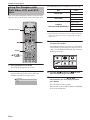
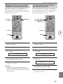
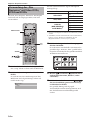
8 En
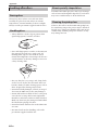
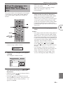
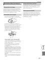
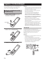
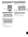
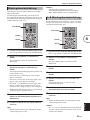
This chapter explains how to install the batteries in
the remote control and how to connect speakers and
other components to the DRX-730.
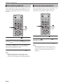
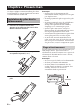
1 Push the tab on the battery compartment
cover in the direction of the arrow and remove
the cover.
2 Insert the supplied batteries into the battery
compartment with the correct polarity
(+ and –).
3 Replace the battery compartment cover.
Notes:
•If the operating range of the remote control
decreases, replace all of the batteries with new
ones.
•Do not use old and new batteries together.
•Do not use different types of batteries together,
such as alkaline and manganese. Although they
may look similar, each type has its own
characteristics.
•When the batteries run out, remove them from
the remote control immediately to prevent an
explosion or acid leak.
•Always follow the battery disposal regulations for
your area.
•If a battery starts leaking, dispose of it
immediately. Be careful not to let leaking battery
acid come into contact with your skin or clothing.
Before inserting new batteries, wipe the battery
compartment clean.
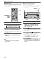
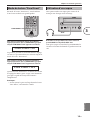
The remote control has an operating range of up to 6
meters (20 feet). When using the remote control,
point it toward the DRX-730’s remote control sensor,
which is next to the display, see below.
Notes:
•Be careful not to spill liquid on the remote
control.
•Be careful not to drop the remote control.
•Do not leave the remote control in the following
places: hot or humid places, such as near a heater
or in a bathroom; extremely cold places; dusty
places.
Chapter 2: Getting Started
Installing batteries in the
remote control
Push here
Operating range
STANDBY/ON
USB PORTABLE PHONES
INPUT
VOLUME
TIMER
HDMI
PROGRESSIVE
30 30
Up to 6 m
(20 feet)

Chapter 2: Getting Started
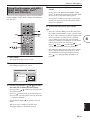
9 En
English
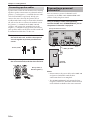
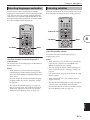
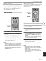
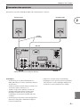
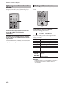
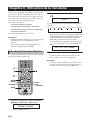
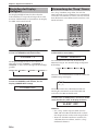
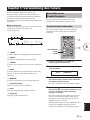
Connect the NX-E700 speakers to the DRX-730 as shown below.
Notes:
•Do not connect the power cable to the DRX-730
until all other connections have been completed.
•Be sure to connect the right speaker to the
terminals labelled “R,” and the left speaker to the
terminals labelled “L”.
•Make sure the exposed strands of each wire are
not touching any other wires or any metal parts of
the DRX-730, as this could seriously damage the
DRX-730 and your speakers.
•Do not connect speakers with an impedance
lower than the minimum impedance stated on the
rear of the DRX-730.
•Use magnetically shielded speakers if you intend
to position them close to a CRT-type TV. If they
cause picture interference, move them away from
the TV.
Connecting speakers
HDMI
MAINS
AM
ANT
ANT
GND
FM
UNBAL.
75
OUT
OPTICAL
VIDEO
OUT IN
MIN
COMPONENT
DIGITALDOCK
AV MONITOR OUT
AUX
OUT
SUBWOOFER
SPEAKERS VIDEO OUT
P
Y
R
P
B
R
R
SPEAKER
6
Left speaker
DRX-730
Right speaker
Speaker cables
(Europe model shown here.)
2

Chapter 2: Getting Started
10 En
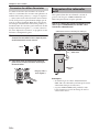
Speaker cables consist of two insulated wires running
together. Speaker connections are polarized and use
positive (+) and negative (–) terminals that are color-
coded red and black, respectively. To help you
connect the wires correctly, the positive wire is
usually marked with a stripe or some other identifier.
All you need to do is to connect the marked wire to
the positive (+) terminals on the DRX-730 and
speakers, and connect the unmarked wire to the
negative (–) terminals. If you get them crossed over,
your speakers will be out of phase and the sound will
be unnatural and lack bass, so take care.
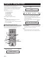
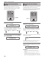
1 Strip about 10 mm (3/8 in.) of insulation from
the end of each wire, and twist the exposed
strands together to prevent possible short
circuits.
2 Push open the speaker terminal lever, insert
the wire into the hole, and then close the lever.
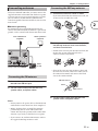
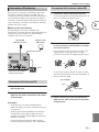
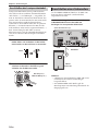
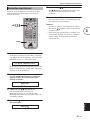
You c an connect a powered subwoofer (sold
separately) to the DRX-730’s SUBWOOFER OUT
jack for a really deep bass sound.
Using an audio pin cable (sold separately),
connect the DRX-730’s SUBWOOFER OUT jack to
the powered subwoofer’s input jack.
Notes:
•Do not connect the power cables to the DRX-730
and powered subwoofer until all other
connections have been completed.
•The SUBWOOFER OUT jack outputs the low-
frequency sounds of a downmix created from all
of the channels available in the source material.
Connecting speaker cables
10 mm (3/8 in.)
Red: positive (+)
Black: negative (–)
Connecting a powered
subwoofer
INPUT
INPUT
HDMI
MAINS
AM
ANT
ANT
GND
FM
UNBAL.
75
OUT
OPTICAL
VIDEO
OUT IN
MIN
COMPONENT
DIGITALDOCK
AV MONITOR OUT
AUX
OUT
SUBWOOFER
SPEAKERS VIDEO OUT
P
Y
R
P
B
R
R
SPEAKER
6
Audio pin cable
Powered
subwoofer
(Europe model shown here.)

Chapter 2: Getting Started
11 En
English
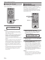
To listen to FM and AM radio, you must connect the
supplied antennas to the DRX-730. If radio reception
is poor in your area or you want to improve reception,
you can connect outdoor FM and AM antennas.
Consult an qualified antenna installer in your area for
more details.
■ Antenna grounding
For maximum safety and minimum interference,
connect the AM ANT GND terminal to a good earth
ground, such as a metal stake driven into moist earth.
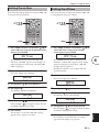
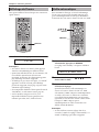
1 Connect the supplied indoor FM antenna to
the DRX-730’s FM ANT jack.
2 Site the antenna away from the DRX-730,
speaker cables, and power cables.
Notes:
•Do not connect the power cable to the DRX-730
until all other connections have been completed.
•Before deciding where to install the antennas
permanently, tune in to an AM or FM radio
station and adjust the position of the AM or FM
antenna, respectively, to find the best reception.
•If you connect an outdoor AM antenna, connect
the supplied AM loop antenna as well.
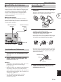
1 Assemble the antenna’s stand as shown.
If you intend to mount the antenna on a wall, you
do not need to assemble the stand.
2 Push open the AM ANT terminal lever, insert
the AM loop antenna’s wires into the holes,
and then close the lever.
•If both of the wires on your antenna are black, this
means they are not polarized and can be
connected either way around.
•If one of the wires on your antenna is white and
the other one is black, connect the white wire to
the AM ANT terminal, and connect the black
wire to the GND terminal.
3 Site the antenna away from the DRX-730,
speaker cables, and power cables.
Connecting antennas
Connecting the FM antenna
HDMI
AM
ANT
ANT
GND
FM
UNBAL.
75
OUT
OPTICAL
VIDEO
T
IN
COMPONENT
DIGITALDOCK
AV MONITOR OUT
AUX VIDEO OUT
P
Y
R
P
B
R
Indoor FM antenna
(supplied)
AM loop antenna
(supplied)
Earth
ground
(Europe model shown here.)
Connecting the AM loop antenna
White
Black
GND terminal
AM ANT terminal
2

Chapter 2: Getting Started
12 En
You c an connect the DRX-730 to a TV by using any
one of four different connection types: HDMI,
component video, composite video, or SCART
(Europe and Russia models). The type you choose
will depend on the connections supported by your
TV. Refer to your TV owner’s manual for details.
HDMI provides the best picture quality. Component
video offers the next best picture quality and the
DRX-730’s component video output supports
progressive scanning for even better picture quality. If
your TV doesn’t support HDMI or component video,
use composite video. Some DRX-730 models have a
SCART jack that can output composite video or RGB
component video.
Notes:
•Do not connect the power cable to the DRX-730
until all other connections have been completed.
•Turn off your TV before connecting it to the
DRX-730.
Tip:
•If your TV has an audio output, you can connect it
to the DRX-730’s AUX IN jacks and listen to your
favorite TV programs through the speakers
connected to the DRX-730.
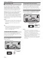
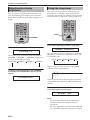
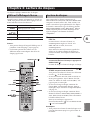
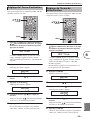
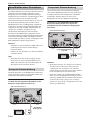
If your TV doesn’t support HDMI or component
video, you can connect the DRX-730 to your TV with
the supplied video pin cable.
Use the supplied video pin cable to connect the
DRX-730’s VIDEO OUT jack to a composite video
input on your TV.
If your TV supports component video but not HDMI,
you can connect the DRX-730 to your TV with a
component video cable. This will provide better
picture quality than a composite video connection.
Using a component video cable (sold separately),
connect the DRX-730’s COMPONENT VIDEO OUT
jacks to a component video input on your TV.
Notes:
•If you connect a TV that does not support
progressive scanning, make sure the Component
Out setting is set to Interlace. If it’s set to
Progressive, the TV may display no picture.
•If you use the COMPONENT VIDEO OUT and
HDMI connections simultaneously, the
COMPONENT VIDEO OUT jacks may output
progressive video regardless of the Component
Out setting.
Connecting a TV
Composite video connection
VIDEO
IN
HDMI
MAINS
AM
ANT
ANT
GND
FM
UNBAL.
75
OUT
OPTICAL
VIDEO
OUT IN
MIN
COMPONENT
DIGITALDOCK
AV MONITOR OUT
AUX
OUT
SUBWOOFER
SPEAKERS VIDEO OUT
P
Y
R
P
B
R
R
SPEAKER
6
Video pin cable
(supplied)
TV
(Europe model shown here.)
Component video connection
Y PB PR
COMPONENT
VIDEO IN
HDMI
MAINS
AM
ANT
ANT
GND
FM
UNBAL.
75
OUT
OPTICAL
VIDEO
OUT IN
MIN
COMPONENT
DIGITALDOCK
AV MONITOR OUT
AUX
OUT
SUBWOOFER
SPEAKERS VIDEO OUT
P
Y
R
P
B
R
R
SPEAKER
6
Component video cable
(sold separately)
TV
(Europe model shown here.)

Chapter 2: Getting Started
13 En
English
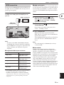
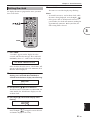
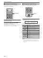
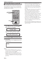
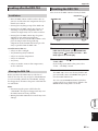
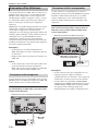
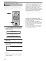
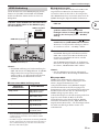
If your TV has an HDMI input, you can connect it to
the DRX-730 with an HDMI cable and enjoy the best
possible picture quality.
Using an HDMI cable (sold separately), connect
the DRX-730’s HDMI jack to an HDMI input on
your TV.
Note:
•You must set the DRX-730’s HDMI resolution
and HDMI color settings to match the capabilities
of your HDMI TV (see page 57). If you select the
wrong resolution, you may loose the picture
altogether.
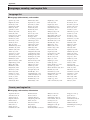
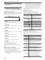
■ Supported HDMI output resolutions
* If your HDMI-compatible TV does not support the above
resolutions, the picture may not display correctly.
* The DRX-730 is designed to be connected to an HDMI
component. If it’s connected to a DVI component, normal
operation may not be possible depending on the DVI
component.
■ HDMI audio output
Normally, the speakers connected to the DRX-730 are
used to output the sound. However, you may want to
listen through your HDMI TV’s speakers, in which
case you can turn HDMI audio output on and off as
follows.
1 Set the DRX-730 to standby.
2 While holding down Stop ( ) on the
DRX-730, press STANDBY/ON, keeping
Stop ( ) pressed until “DVD — NO REQ.”
appears on the display.
3 Press Play/Pause ( / ) repeatedly to select
“HDMI AUDIO ON.”
If you change your mind at this point, select
“DVD — NO REQ.” instead.
4 Press STANDBY/ON.
HDMI Audio output is turned on and the
DRX-730 goes on standby. Press STANDBY/ON
again to turn it back on.
To turn HDMI Audio output off, repeat the above
procedure but select “HDMI AUDIO OFF” in
step 3.
Note:
•The audio output by the HDMI jack is always
2-channel PCM.
■ About HDMI
HDMI stands for High-Definition Multimedia
Interface. An extension of the DVI (Digital Video
Interface) standard used to connect computer
displays, HDMI was designed as the next generation
digital interface standard for TVs and AV equipment,
allowing uncompressed digital video and digital
audio in various formats to be delivered on a single
cable. With HDMI, separate cables for video and
audio connections are no longer necessary. And
because it’s digital, it delivers unimpaired high quality
video and audio. In addition, HDMI supports the
HDCP (High Bandwidth Digital Content Protection)
system that’s used to protect copyrighted video and
audio content from illegal copying.
HDMI connection
North America models Other models
1080p/60 Hz 1080p/60 Hz (NTSC)
1080p/50 Hz (PAL)
1080i/60 Hz 1080i/60 Hz (NTSC)
1080i/50 Hz (PAL)
720p/60 Hz 720p/60 Hz (NTSC)
720p/50 Hz (PAL)
480p/60 Hz 480p/60 Hz (NTSC)
576p/50 Hz (PAL)
480i/60 Hz 480i/60 Hz (NTSC)
576i/50 Hz (PAL)
HDMI
IN
HDMI
MAINS
AM
ANT
ANT
GND
FM
UNBAL.
75
OUT
OPTICAL
VIDEO
OUT IN
MIN
COMPONENT
DIGITALDOCK
AV MONITOR OUT
AUX
OUT
SUBWOOFER
SPEAKERS VIDEO OUT
P
Y
R
P
B
R
R
SPEAKER
6
HDMI cable
(sold separately)
HDMI-compatible TV
(Europe model shown here.)
2

Chapter 2: Getting Started
14 En
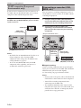
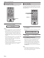
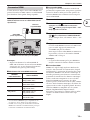
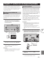
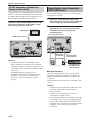
If your TV has a SCART jack, you can connect it to
the DRX-730’s AV MONITOR OUT jack and enjoy
composite video or RGB component video.
Using a SCART cable (sold separately), connect
the DRX-730’s AV MONITOR OUT jack to a SCART
input on your TV.
Notes:
•By default, the AV MONITOR OUT jack is set to
output composite video. To output RGB
component video, change the AV Monitor Out
setting to RGB (see page 57).
•To use the AV MONITOR OUT jack’s RGB
component video capability, you must use a
SCART cable with all 21 pins wired.
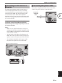
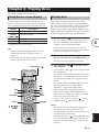
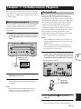
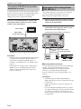
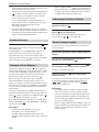
You c an connect a recording component, such as a
CDR, MDR, or casette recorder, to the DRX-730 for
recording and playback.
1 Using an audio pin cable (sold separately),
connect the DRX-730’s AUX OUT jacks to the
audio input on your recording component.
2 Using another audio pin cable (sold
separately), connect the DRX-730’s AUX IN
jacks to the audio output on your recording
component.
■ Digital recording
If your recording component has an optical digital
input, you can connect it to the DRX-730’s OPTICAL
DIGITAL OUT jack and record digitally.
See “Recording” on page 53 for more details.
Notes:
•Do not connect the power cable to the DRX-730
until all other connections have been completed.
•Turn off the recording component before
connecting it to the DRX-730.
•The OPTICAL DIGITAL OUT outputs audio
only when the input source is DVD or USB, and
with some discs and files, recording may not be
possible due to copy protection.
SCART connection (Europe and
Russia models only)
HDMI
MAINS
AM
ANT
ANT
GND
FM
UNBAL.
75
OUT
OPTICAL
VIDEO
OUT IN
MIN
COMPONENT
DIGITALDOCK
AV MONITOR OUT
AUX
OUT
SUBWOOFER
SPEAKERS VIDEO OUT
P
Y
R
P
B
R
R
SPEAKER
6
SCART input
SCART cable
(sold separately)
TV
(Europe model shown here.)
Connecting a recorder (CDR,
MDR, etc.)
IN
AUDIO
L
IN
OUT
R
OPTICAL
DIGITAL
HDMI
AM
ANT
ANT
GND
FM
UNBAL.
75
OUT
OPTICAL
VIDEO
OUT IN
COMPONENT
DIGITALDOCK
AV MONITOR OUT
AUX
OUT
SUBWOOFER
VIDEO OUT
P
Y
R
P
B
R
Recording component
(CDR, MDR, casette deck)
Audio pin
cables (sold
separately)
Optical cable
(sold separately)
(Europe model shown here.)
Sidan laddas ...
Sidan laddas ...
Sidan laddas ...
Sidan laddas ...
Sidan laddas ...
Sidan laddas ...
Sidan laddas ...
Sidan laddas ...
Sidan laddas ...
Sidan laddas ...
Sidan laddas ...
Sidan laddas ...
Sidan laddas ...
Sidan laddas ...
Sidan laddas ...
Sidan laddas ...
Sidan laddas ...
Sidan laddas ...
Sidan laddas ...
Sidan laddas ...
Sidan laddas ...
Sidan laddas ...
Sidan laddas ...
Sidan laddas ...
Sidan laddas ...
Sidan laddas ...
Sidan laddas ...
Sidan laddas ...
Sidan laddas ...
Sidan laddas ...
Sidan laddas ...
Sidan laddas ...
Sidan laddas ...
Sidan laddas ...
Sidan laddas ...
Sidan laddas ...
Sidan laddas ...
Sidan laddas ...
Sidan laddas ...
Sidan laddas ...
Sidan laddas ...
Sidan laddas ...
Sidan laddas ...
Sidan laddas ...
Sidan laddas ...
Sidan laddas ...
Sidan laddas ...
Sidan laddas ...
Sidan laddas ...
Sidan laddas ...
Sidan laddas ...
Sidan laddas ...
Sidan laddas ...
Sidan laddas ...
Sidan laddas ...
Sidan laddas ...
Sidan laddas ...
Sidan laddas ...
Sidan laddas ...
Sidan laddas ...
Sidan laddas ...
Sidan laddas ...
Sidan laddas ...
Sidan laddas ...
Sidan laddas ...
Sidan laddas ...
Sidan laddas ...
Sidan laddas ...
Sidan laddas ...
Sidan laddas ...
Sidan laddas ...
Sidan laddas ...
Sidan laddas ...
Sidan laddas ...
Sidan laddas ...
Sidan laddas ...
Sidan laddas ...
Sidan laddas ...
Sidan laddas ...
Sidan laddas ...
Sidan laddas ...
Sidan laddas ...
Sidan laddas ...
Sidan laddas ...
Sidan laddas ...
Sidan laddas ...
Sidan laddas ...
Sidan laddas ...
Sidan laddas ...
Sidan laddas ...
Sidan laddas ...
Sidan laddas ...
Sidan laddas ...
Sidan laddas ...
Sidan laddas ...
Sidan laddas ...
Sidan laddas ...
Sidan laddas ...
Sidan laddas ...
Sidan laddas ...
Sidan laddas ...
Sidan laddas ...
Sidan laddas ...
Sidan laddas ...
Sidan laddas ...
Sidan laddas ...
Sidan laddas ...
Sidan laddas ...
Sidan laddas ...
Sidan laddas ...
Sidan laddas ...
Sidan laddas ...
Sidan laddas ...
Sidan laddas ...
Sidan laddas ...
Sidan laddas ...
Sidan laddas ...
Sidan laddas ...
Sidan laddas ...
Sidan laddas ...
Sidan laddas ...
Sidan laddas ...
Sidan laddas ...
Sidan laddas ...
Sidan laddas ...
Sidan laddas ...
Sidan laddas ...
Sidan laddas ...
Sidan laddas ...
Sidan laddas ...
Sidan laddas ...
Sidan laddas ...
Sidan laddas ...
Sidan laddas ...
Sidan laddas ...
Sidan laddas ...
Sidan laddas ...
Sidan laddas ...
Sidan laddas ...
Sidan laddas ...
Sidan laddas ...
Sidan laddas ...
Sidan laddas ...
Sidan laddas ...
Sidan laddas ...
Sidan laddas ...
Sidan laddas ...
Sidan laddas ...
Sidan laddas ...
Sidan laddas ...
Sidan laddas ...
Sidan laddas ...
Sidan laddas ...
Sidan laddas ...
Sidan laddas ...
Sidan laddas ...
Sidan laddas ...
Sidan laddas ...
Sidan laddas ...
Sidan laddas ...
Sidan laddas ...
Sidan laddas ...
Sidan laddas ...
Sidan laddas ...
Sidan laddas ...
Sidan laddas ...
Sidan laddas ...
Sidan laddas ...
Sidan laddas ...
Sidan laddas ...
Sidan laddas ...
Sidan laddas ...
Sidan laddas ...
Sidan laddas ...
Sidan laddas ...
Sidan laddas ...
Sidan laddas ...
Sidan laddas ...
Sidan laddas ...
Sidan laddas ...
Sidan laddas ...
Sidan laddas ...
Sidan laddas ...
Sidan laddas ...
Sidan laddas ...
Sidan laddas ...
Sidan laddas ...
Sidan laddas ...
Sidan laddas ...
Sidan laddas ...
Sidan laddas ...
Sidan laddas ...
Sidan laddas ...
Sidan laddas ...
Sidan laddas ...
Sidan laddas ...
Sidan laddas ...
Sidan laddas ...
Sidan laddas ...
Sidan laddas ...
Sidan laddas ...
Sidan laddas ...
Sidan laddas ...
Sidan laddas ...
Sidan laddas ...
Sidan laddas ...
Sidan laddas ...
Sidan laddas ...
Sidan laddas ...
Sidan laddas ...
Sidan laddas ...
Sidan laddas ...
Sidan laddas ...
Sidan laddas ...
Sidan laddas ...
Sidan laddas ...
Sidan laddas ...
Sidan laddas ...
Sidan laddas ...
Sidan laddas ...
Sidan laddas ...
Sidan laddas ...
Sidan laddas ...
Sidan laddas ...
Sidan laddas ...
Sidan laddas ...
Sidan laddas ...
Sidan laddas ...
Sidan laddas ...
Sidan laddas ...
Sidan laddas ...
Sidan laddas ...
Sidan laddas ...
Sidan laddas ...
Sidan laddas ...
Sidan laddas ...
Sidan laddas ...
Sidan laddas ...
Sidan laddas ...
Sidan laddas ...
Sidan laddas ...
Sidan laddas ...
Sidan laddas ...
Sidan laddas ...
Sidan laddas ...
Sidan laddas ...
Sidan laddas ...
Sidan laddas ...
Sidan laddas ...
Sidan laddas ...
Sidan laddas ...
Sidan laddas ...
Sidan laddas ...
Sidan laddas ...
Sidan laddas ...
Sidan laddas ...
Sidan laddas ...
Sidan laddas ...
Sidan laddas ...
Sidan laddas ...
Sidan laddas ...
Sidan laddas ...
Sidan laddas ...
Sidan laddas ...
Sidan laddas ...
Sidan laddas ...
Sidan laddas ...
Sidan laddas ...
Sidan laddas ...
Sidan laddas ...
Sidan laddas ...
Sidan laddas ...
Sidan laddas ...
Sidan laddas ...
Sidan laddas ...
Sidan laddas ...
Sidan laddas ...
Sidan laddas ...
Sidan laddas ...
Sidan laddas ...
Sidan laddas ...
Sidan laddas ...
Sidan laddas ...
Sidan laddas ...
Sidan laddas ...
Sidan laddas ...
Sidan laddas ...
Sidan laddas ...
Sidan laddas ...
Sidan laddas ...
Sidan laddas ...
Sidan laddas ...
Sidan laddas ...
Sidan laddas ...
Sidan laddas ...
Sidan laddas ...
Sidan laddas ...
Sidan laddas ...
Sidan laddas ...
Sidan laddas ...
Sidan laddas ...
Sidan laddas ...
Sidan laddas ...
Sidan laddas ...
Sidan laddas ...
Sidan laddas ...
Sidan laddas ...
Sidan laddas ...
Sidan laddas ...
Sidan laddas ...
Sidan laddas ...
Sidan laddas ...
Sidan laddas ...
Sidan laddas ...
Sidan laddas ...
Sidan laddas ...
Sidan laddas ...
Sidan laddas ...
Sidan laddas ...
Sidan laddas ...
Sidan laddas ...
Sidan laddas ...
Sidan laddas ...
Sidan laddas ...
Sidan laddas ...
Sidan laddas ...
Sidan laddas ...
Sidan laddas ...
Sidan laddas ...
Sidan laddas ...
Sidan laddas ...
Sidan laddas ...
Sidan laddas ...
Sidan laddas ...
Sidan laddas ...
Sidan laddas ...
Sidan laddas ...
Sidan laddas ...
Sidan laddas ...
Sidan laddas ...
Sidan laddas ...
Sidan laddas ...
Sidan laddas ...
Sidan laddas ...
Sidan laddas ...
Sidan laddas ...
Sidan laddas ...
Sidan laddas ...
Sidan laddas ...
Sidan laddas ...
Sidan laddas ...
Sidan laddas ...
Sidan laddas ...
Sidan laddas ...
Sidan laddas ...
Sidan laddas ...
Sidan laddas ...
Sidan laddas ...
Sidan laddas ...
Sidan laddas ...
Sidan laddas ...
Sidan laddas ...
Sidan laddas ...
Sidan laddas ...
Sidan laddas ...
Sidan laddas ...
Sidan laddas ...
Sidan laddas ...
Sidan laddas ...
Sidan laddas ...
Sidan laddas ...
Sidan laddas ...
Sidan laddas ...
Sidan laddas ...
Sidan laddas ...
Sidan laddas ...
Sidan laddas ...
Sidan laddas ...
Sidan laddas ...
Sidan laddas ...
Sidan laddas ...
Sidan laddas ...
Sidan laddas ...
Sidan laddas ...
Sidan laddas ...
Sidan laddas ...
Sidan laddas ...
Sidan laddas ...
Sidan laddas ...
Sidan laddas ...
Sidan laddas ...
Sidan laddas ...
Sidan laddas ...
Sidan laddas ...
Sidan laddas ...
Sidan laddas ...
Sidan laddas ...
Sidan laddas ...
Sidan laddas ...
Sidan laddas ...
Sidan laddas ...
Sidan laddas ...
Sidan laddas ...
Sidan laddas ...
Sidan laddas ...
Sidan laddas ...
Sidan laddas ...
Sidan laddas ...
Sidan laddas ...
Sidan laddas ...
Sidan laddas ...
Sidan laddas ...
Sidan laddas ...
Sidan laddas ...
Sidan laddas ...
Sidan laddas ...
Sidan laddas ...
Sidan laddas ...
Sidan laddas ...
Sidan laddas ...
Sidan laddas ...
Sidan laddas ...
Sidan laddas ...
Sidan laddas ...
Sidan laddas ...
Sidan laddas ...
Sidan laddas ...
Sidan laddas ...
Sidan laddas ...
Sidan laddas ...
Sidan laddas ...
Sidan laddas ...
Sidan laddas ...
Sidan laddas ...
Sidan laddas ...
Sidan laddas ...
Sidan laddas ...
Sidan laddas ...
Sidan laddas ...
Sidan laddas ...
Sidan laddas ...
Sidan laddas ...
Sidan laddas ...
Sidan laddas ...
Sidan laddas ...
Sidan laddas ...
Sidan laddas ...
Sidan laddas ...
Sidan laddas ...
Sidan laddas ...
Sidan laddas ...
Sidan laddas ...
Sidan laddas ...
Sidan laddas ...
Sidan laddas ...
Sidan laddas ...
Sidan laddas ...
Sidan laddas ...
Sidan laddas ...
Sidan laddas ...
Sidan laddas ...
Sidan laddas ...
Sidan laddas ...
Sidan laddas ...
Sidan laddas ...
Sidan laddas ...
Sidan laddas ...
Sidan laddas ...
Sidan laddas ...
Sidan laddas ...
Sidan laddas ...
Sidan laddas ...
Sidan laddas ...
Sidan laddas ...
Sidan laddas ...
Sidan laddas ...
Sidan laddas ...
Sidan laddas ...
Sidan laddas ...
Sidan laddas ...
Sidan laddas ...
Sidan laddas ...
Sidan laddas ...
Sidan laddas ...
Sidan laddas ...
Sidan laddas ...
Sidan laddas ...
Sidan laddas ...
Sidan laddas ...
Sidan laddas ...
Sidan laddas ...
Sidan laddas ...
Sidan laddas ...
Sidan laddas ...
Sidan laddas ...
Sidan laddas ...
Sidan laddas ...
Sidan laddas ...
Sidan laddas ...
Sidan laddas ...
Sidan laddas ...
Sidan laddas ...
Sidan laddas ...
Sidan laddas ...
Sidan laddas ...
Sidan laddas ...
Sidan laddas ...
Sidan laddas ...
Sidan laddas ...
Sidan laddas ...
Sidan laddas ...
Sidan laddas ...
Sidan laddas ...
Sidan laddas ...
Sidan laddas ...
Sidan laddas ...
Sidan laddas ...
Sidan laddas ...
Sidan laddas ...
Sidan laddas ...
Sidan laddas ...
Sidan laddas ...
Sidan laddas ...
Sidan laddas ...
Sidan laddas ...
Sidan laddas ...
Sidan laddas ...
Sidan laddas ...
Sidan laddas ...
Sidan laddas ...
Sidan laddas ...
Sidan laddas ...
Sidan laddas ...
Sidan laddas ...
Sidan laddas ...
Sidan laddas ...
Sidan laddas ...
Sidan laddas ...
Sidan laddas ...
Sidan laddas ...
Sidan laddas ...
Sidan laddas ...
Sidan laddas ...
Sidan laddas ...
Sidan laddas ...
Sidan laddas ...
Sidan laddas ...
Sidan laddas ...
Sidan laddas ...
Sidan laddas ...
Sidan laddas ...
Sidan laddas ...
Sidan laddas ...
Sidan laddas ...
Sidan laddas ...
Sidan laddas ...
Sidan laddas ...
Sidan laddas ...
Sidan laddas ...
Sidan laddas ...
Sidan laddas ...
Sidan laddas ...
Sidan laddas ...
Sidan laddas ...
Sidan laddas ...
Sidan laddas ...
Sidan laddas ...
Sidan laddas ...
Sidan laddas ...
Sidan laddas ...
Sidan laddas ...
Sidan laddas ...
Sidan laddas ...
Sidan laddas ...
Sidan laddas ...
Sidan laddas ...
Sidan laddas ...
Sidan laddas ...
Sidan laddas ...
Sidan laddas ...
Sidan laddas ...
Sidan laddas ...
Sidan laddas ...
Sidan laddas ...
Sidan laddas ...
Sidan laddas ...
Sidan laddas ...
Sidan laddas ...
Sidan laddas ...
Sidan laddas ...
Sidan laddas ...
Sidan laddas ...
Sidan laddas ...
Sidan laddas ...
Sidan laddas ...
Sidan laddas ...
Sidan laddas ...
Sidan laddas ...
Sidan laddas ...
Sidan laddas ...
Sidan laddas ...
Sidan laddas ...
Sidan laddas ...
Sidan laddas ...
Sidan laddas ...
Sidan laddas ...
-
 1
1
-
 2
2
-
 3
3
-
 4
4
-
 5
5
-
 6
6
-
 7
7
-
 8
8
-
 9
9
-
 10
10
-
 11
11
-
 12
12
-
 13
13
-
 14
14
-
 15
15
-
 16
16
-
 17
17
-
 18
18
-
 19
19
-
 20
20
-
 21
21
-
 22
22
-
 23
23
-
 24
24
-
 25
25
-
 26
26
-
 27
27
-
 28
28
-
 29
29
-
 30
30
-
 31
31
-
 32
32
-
 33
33
-
 34
34
-
 35
35
-
 36
36
-
 37
37
-
 38
38
-
 39
39
-
 40
40
-
 41
41
-
 42
42
-
 43
43
-
 44
44
-
 45
45
-
 46
46
-
 47
47
-
 48
48
-
 49
49
-
 50
50
-
 51
51
-
 52
52
-
 53
53
-
 54
54
-
 55
55
-
 56
56
-
 57
57
-
 58
58
-
 59
59
-
 60
60
-
 61
61
-
 62
62
-
 63
63
-
 64
64
-
 65
65
-
 66
66
-
 67
67
-
 68
68
-
 69
69
-
 70
70
-
 71
71
-
 72
72
-
 73
73
-
 74
74
-
 75
75
-
 76
76
-
 77
77
-
 78
78
-
 79
79
-
 80
80
-
 81
81
-
 82
82
-
 83
83
-
 84
84
-
 85
85
-
 86
86
-
 87
87
-
 88
88
-
 89
89
-
 90
90
-
 91
91
-
 92
92
-
 93
93
-
 94
94
-
 95
95
-
 96
96
-
 97
97
-
 98
98
-
 99
99
-
 100
100
-
 101
101
-
 102
102
-
 103
103
-
 104
104
-
 105
105
-
 106
106
-
 107
107
-
 108
108
-
 109
109
-
 110
110
-
 111
111
-
 112
112
-
 113
113
-
 114
114
-
 115
115
-
 116
116
-
 117
117
-
 118
118
-
 119
119
-
 120
120
-
 121
121
-
 122
122
-
 123
123
-
 124
124
-
 125
125
-
 126
126
-
 127
127
-
 128
128
-
 129
129
-
 130
130
-
 131
131
-
 132
132
-
 133
133
-
 134
134
-
 135
135
-
 136
136
-
 137
137
-
 138
138
-
 139
139
-
 140
140
-
 141
141
-
 142
142
-
 143
143
-
 144
144
-
 145
145
-
 146
146
-
 147
147
-
 148
148
-
 149
149
-
 150
150
-
 151
151
-
 152
152
-
 153
153
-
 154
154
-
 155
155
-
 156
156
-
 157
157
-
 158
158
-
 159
159
-
 160
160
-
 161
161
-
 162
162
-
 163
163
-
 164
164
-
 165
165
-
 166
166
-
 167
167
-
 168
168
-
 169
169
-
 170
170
-
 171
171
-
 172
172
-
 173
173
-
 174
174
-
 175
175
-
 176
176
-
 177
177
-
 178
178
-
 179
179
-
 180
180
-
 181
181
-
 182
182
-
 183
183
-
 184
184
-
 185
185
-
 186
186
-
 187
187
-
 188
188
-
 189
189
-
 190
190
-
 191
191
-
 192
192
-
 193
193
-
 194
194
-
 195
195
-
 196
196
-
 197
197
-
 198
198
-
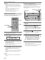 199
199
-
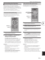 200
200
-
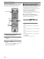 201
201
-
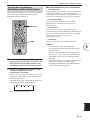 202
202
-
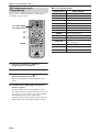 203
203
-
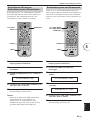 204
204
-
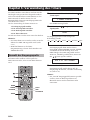 205
205
-
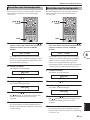 206
206
-
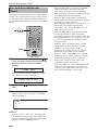 207
207
-
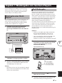 208
208
-
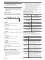 209
209
-
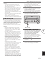 210
210
-
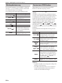 211
211
-
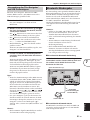 212
212
-
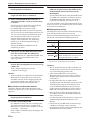 213
213
-
 214
214
-
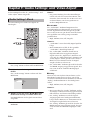 215
215
-
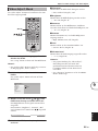 216
216
-
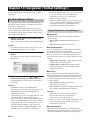 217
217
-
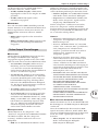 218
218
-
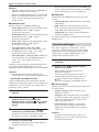 219
219
-
 220
220
-
 221
221
-
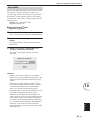 222
222
-
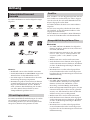 223
223
-
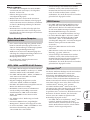 224
224
-
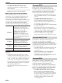 225
225
-
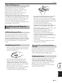 226
226
-
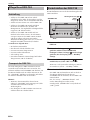 227
227
-
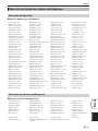 228
228
-
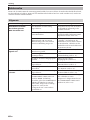 229
229
-
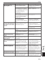 230
230
-
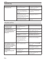 231
231
-
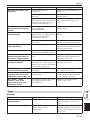 232
232
-
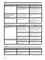 233
233
-
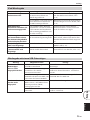 234
234
-
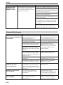 235
235
-
 236
236
-
 237
237
-
 238
238
-
 239
239
-
 240
240
-
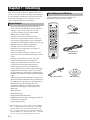 241
241
-
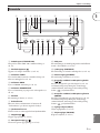 242
242
-
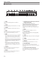 243
243
-
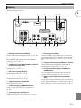 244
244
-
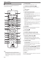 245
245
-
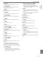 246
246
-
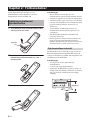 247
247
-
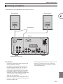 248
248
-
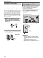 249
249
-
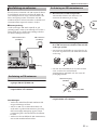 250
250
-
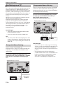 251
251
-
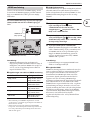 252
252
-
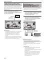 253
253
-
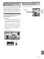 254
254
-
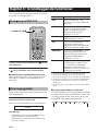 255
255
-
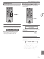 256
256
-
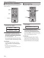 257
257
-
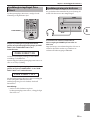 258
258
-
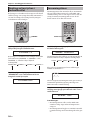 259
259
-
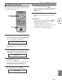 260
260
-
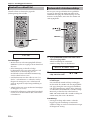 261
261
-
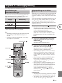 262
262
-
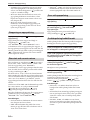 263
263
-
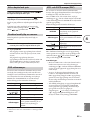 264
264
-
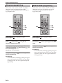 265
265
-
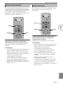 266
266
-
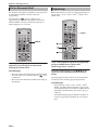 267
267
-
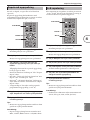 268
268
-
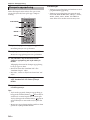 269
269
-
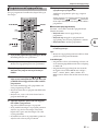 270
270
-
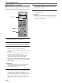 271
271
-
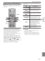 272
272
-
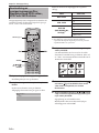 273
273
-
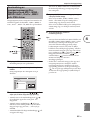 274
274
-
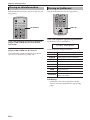 275
275
-
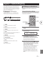 276
276
-
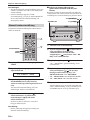 277
277
-
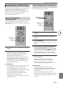 278
278
-
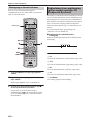 279
279
-
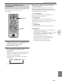 280
280
-
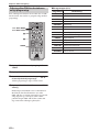 281
281
-
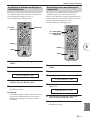 282
282
-
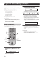 283
283
-
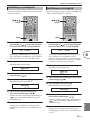 284
284
-
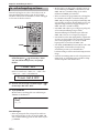 285
285
-
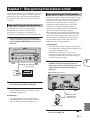 286
286
-
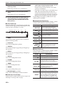 287
287
-
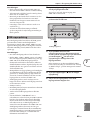 288
288
-
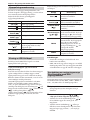 289
289
-
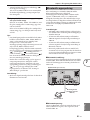 290
290
-
 291
291
-
 292
292
-
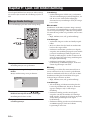 293
293
-
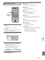 294
294
-
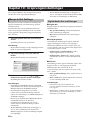 295
295
-
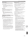 296
296
-
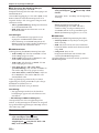 297
297
-
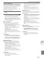 298
298
-
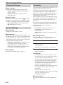 299
299
-
 300
300
-
 301
301
-
 302
302
-
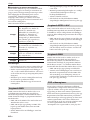 303
303
-
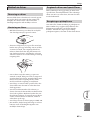 304
304
-
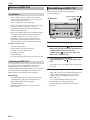 305
305
-
 306
306
-
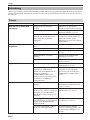 307
307
-
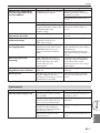 308
308
-
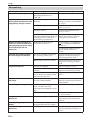 309
309
-
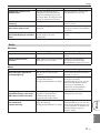 310
310
-
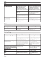 311
311
-
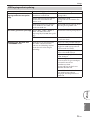 312
312
-
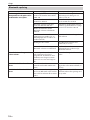 313
313
-
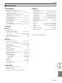 314
314
-
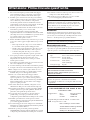 315
315
-
 316
316
-
 317
317
-
 318
318
-
 319
319
-
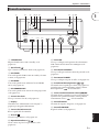 320
320
-
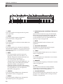 321
321
-
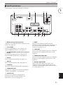 322
322
-
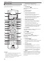 323
323
-
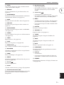 324
324
-
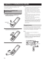 325
325
-
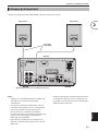 326
326
-
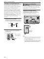 327
327
-
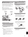 328
328
-
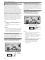 329
329
-
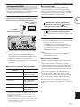 330
330
-
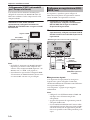 331
331
-
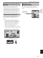 332
332
-
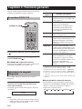 333
333
-
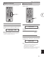 334
334
-
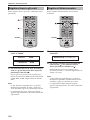 335
335
-
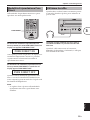 336
336
-
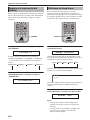 337
337
-
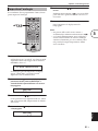 338
338
-
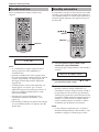 339
339
-
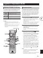 340
340
-
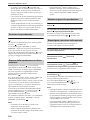 341
341
-
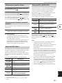 342
342
-
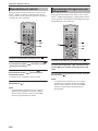 343
343
-
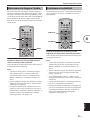 344
344
-
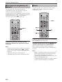 345
345
-
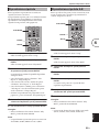 346
346
-
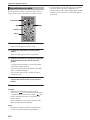 347
347
-
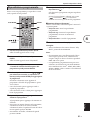 348
348
-
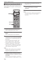 349
349
-
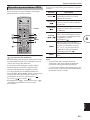 350
350
-
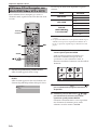 351
351
-
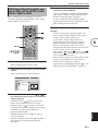 352
352
-
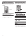 353
353
-
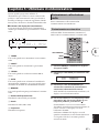 354
354
-
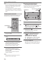 355
355
-
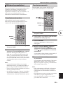 356
356
-
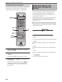 357
357
-
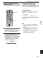 358
358
-
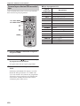 359
359
-
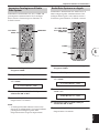 360
360
-
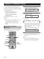 361
361
-
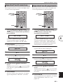 362
362
-
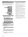 363
363
-
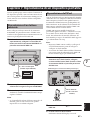 364
364
-
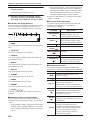 365
365
-
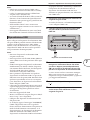 366
366
-
 367
367
-
 368
368
-
 369
369
-
 370
370
-
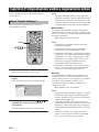 371
371
-
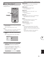 372
372
-
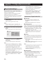 373
373
-
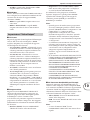 374
374
-
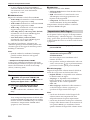 375
375
-
 376
376
-
 377
377
-
 378
378
-
 379
379
-
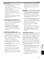 380
380
-
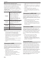 381
381
-
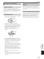 382
382
-
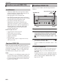 383
383
-
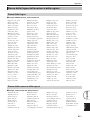 384
384
-
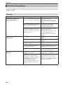 385
385
-
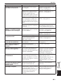 386
386
-
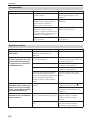 387
387
-
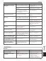 388
388
-
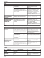 389
389
-
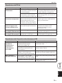 390
390
-
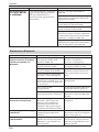 391
391
-
 392
392
-
 393
393
-
 394
394
-
 395
395
-
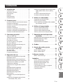 396
396
-
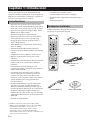 397
397
-
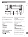 398
398
-
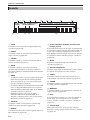 399
399
-
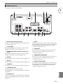 400
400
-
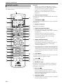 401
401
-
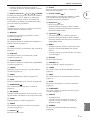 402
402
-
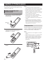 403
403
-
 404
404
-
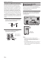 405
405
-
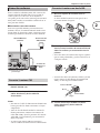 406
406
-
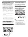 407
407
-
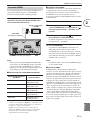 408
408
-
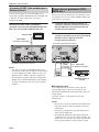 409
409
-
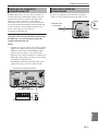 410
410
-
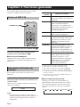 411
411
-
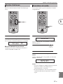 412
412
-
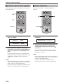 413
413
-
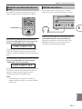 414
414
-
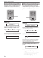 415
415
-
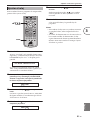 416
416
-
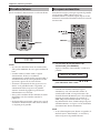 417
417
-
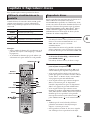 418
418
-
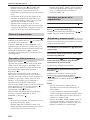 419
419
-
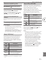 420
420
-
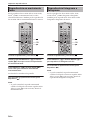 421
421
-
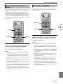 422
422
-
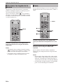 423
423
-
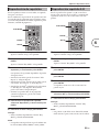 424
424
-
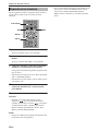 425
425
-
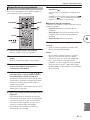 426
426
-
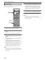 427
427
-
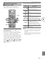 428
428
-
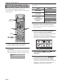 429
429
-
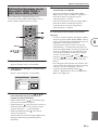 430
430
-
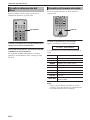 431
431
-
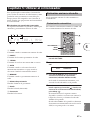 432
432
-
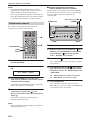 433
433
-
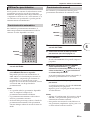 434
434
-
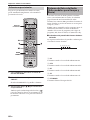 435
435
-
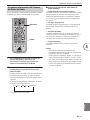 436
436
-
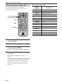 437
437
-
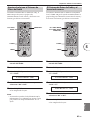 438
438
-
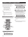 439
439
-
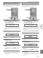 440
440
-
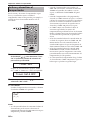 441
441
-
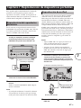 442
442
-
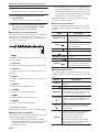 443
443
-
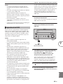 444
444
-
 445
445
-
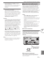 446
446
-
 447
447
-
 448
448
-
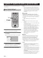 449
449
-
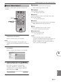 450
450
-
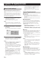 451
451
-
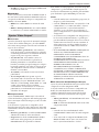 452
452
-
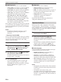 453
453
-
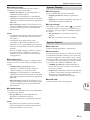 454
454
-
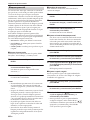 455
455
-
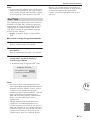 456
456
-
 457
457
-
 458
458
-
 459
459
-
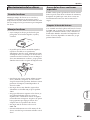 460
460
-
 461
461
-
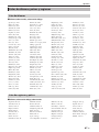 462
462
-
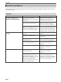 463
463
-
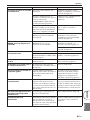 464
464
-
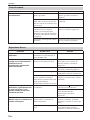 465
465
-
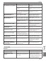 466
466
-
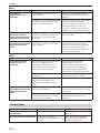 467
467
-
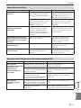 468
468
-
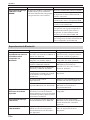 469
469
-
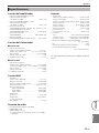 470
470
-
 471
471
-
 472
472
-
 473
473
-
 474
474
-
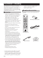 475
475
-
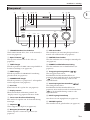 476
476
-
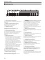 477
477
-
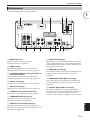 478
478
-
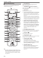 479
479
-
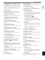 480
480
-
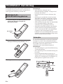 481
481
-
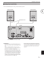 482
482
-
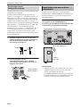 483
483
-
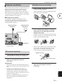 484
484
-
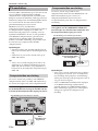 485
485
-
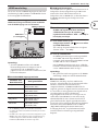 486
486
-
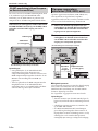 487
487
-
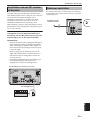 488
488
-
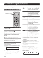 489
489
-
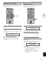 490
490
-
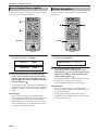 491
491
-
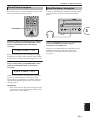 492
492
-
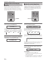 493
493
-
 494
494
-
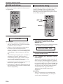 495
495
-
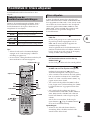 496
496
-
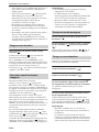 497
497
-
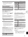 498
498
-
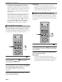 499
499
-
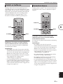 500
500
-
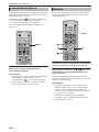 501
501
-
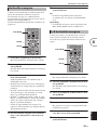 502
502
-
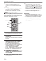 503
503
-
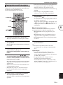 504
504
-
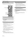 505
505
-
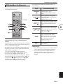 506
506
-
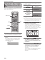 507
507
-
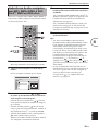 508
508
-
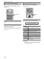 509
509
-
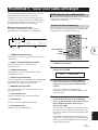 510
510
-
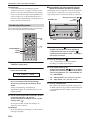 511
511
-
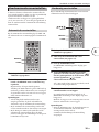 512
512
-
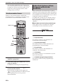 513
513
-
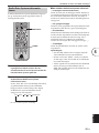 514
514
-
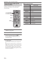 515
515
-
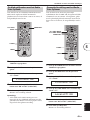 516
516
-
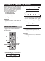 517
517
-
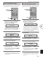 518
518
-
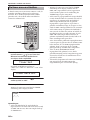 519
519
-
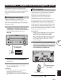 520
520
-
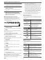 521
521
-
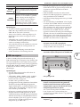 522
522
-
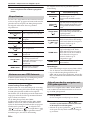 523
523
-
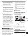 524
524
-
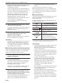 525
525
-
 526
526
-
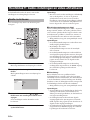 527
527
-
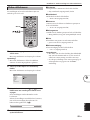 528
528
-
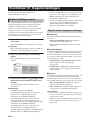 529
529
-
 530
530
-
 531
531
-
 532
532
-
 533
533
-
 534
534
-
 535
535
-
 536
536
-
 537
537
-
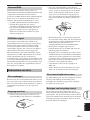 538
538
-
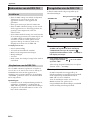 539
539
-
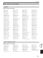 540
540
-
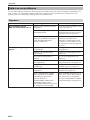 541
541
-
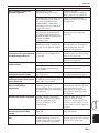 542
542
-
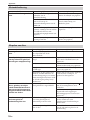 543
543
-
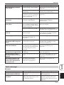 544
544
-
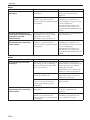 545
545
-
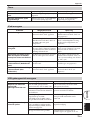 546
546
-
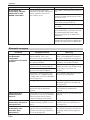 547
547
-
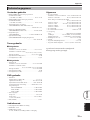 548
548
-
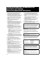 549
549
-
 550
550
-
 551
551
-
 552
552
-
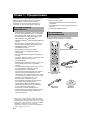 553
553
-
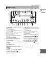 554
554
-
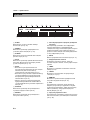 555
555
-
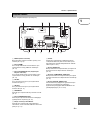 556
556
-
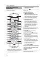 557
557
-
 558
558
-
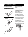 559
559
-
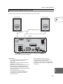 560
560
-
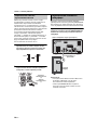 561
561
-
 562
562
-
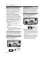 563
563
-
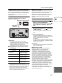 564
564
-
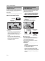 565
565
-
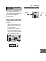 566
566
-
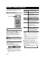 567
567
-
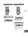 568
568
-
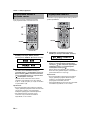 569
569
-
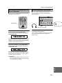 570
570
-
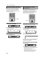 571
571
-
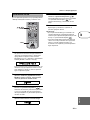 572
572
-
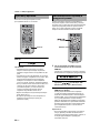 573
573
-
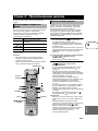 574
574
-
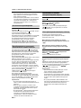 575
575
-
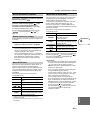 576
576
-
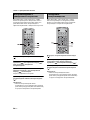 577
577
-
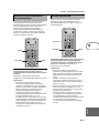 578
578
-
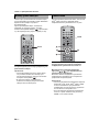 579
579
-
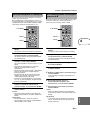 580
580
-
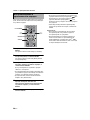 581
581
-
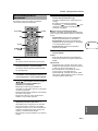 582
582
-
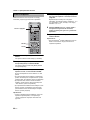 583
583
-
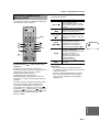 584
584
-
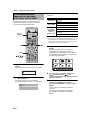 585
585
-
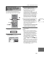 586
586
-
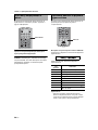 587
587
-
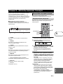 588
588
-
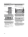 589
589
-
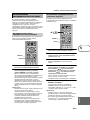 590
590
-
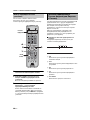 591
591
-
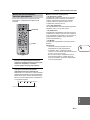 592
592
-
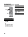 593
593
-
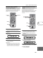 594
594
-
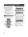 595
595
-
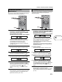 596
596
-
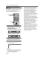 597
597
-
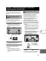 598
598
-
 599
599
-
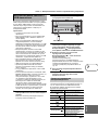 600
600
-
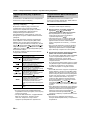 601
601
-
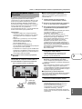 602
602
-
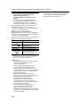 603
603
-
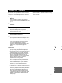 604
604
-
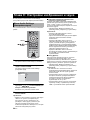 605
605
-
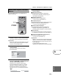 606
606
-
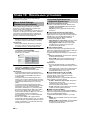 607
607
-
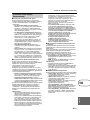 608
608
-
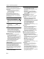 609
609
-
 610
610
-
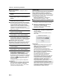 611
611
-
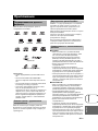 612
612
-
 613
613
-
 614
614
-
 615
615
-
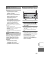 616
616
-
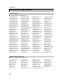 617
617
-
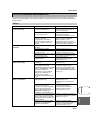 618
618
-
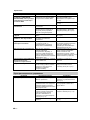 619
619
-
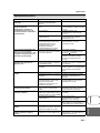 620
620
-
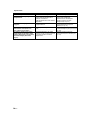 621
621
-
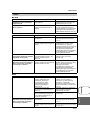 622
622
-
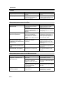 623
623
-
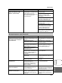 624
624
-
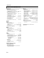 625
625
-
 626
626


Yamaha DRX-730 Bruksanvisning
- Kategori
- DVD-spelare
- Typ
- Bruksanvisning
- Denna manual är också lämplig för
på andra språk
- italiano: Yamaha DRX-730 Manuale del proprietario
- español: Yamaha DRX-730 El manual del propietario
- Deutsch: Yamaha DRX-730 Bedienungsanleitung
- français: Yamaha DRX-730 Le manuel du propriétaire
- Türkçe: Yamaha DRX-730 El kitabı
- English: Yamaha DRX-730 Owner's manual
- dansk: Yamaha DRX-730 Brugervejledning
- suomi: Yamaha DRX-730 Omistajan opas
- Nederlands: Yamaha DRX-730 de handleiding
- română: Yamaha DRX-730 Manualul proprietarului