Sentiotec RS485 Connection Användarmanual
- Typ
- Användarmanual

EN
DE
FR
IT
FI
Version 08/22 ID no. 1-027-269
SV
Interface documentation
English
RS485 Connection
Compatible sauna control units:
CMD RS485
Device
●PRO B2 / B3
●PRO C2 / C3
●Home.com4
●PRO D

Table of Contents
1. Important safety information 3
2. Description 4
3. Functional scope 5
4. Settings 6
5. Overview of commands 6
5.1. General information 6
5.2. Command list 7
6. Examples 12
7. Troubleshooting 13
8. Error messages 14

EN
Installation instructions, only for experts p. 3/14
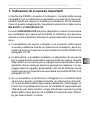
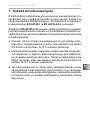
1. Important safety information
The RS485 interface enables the connection of the compatible
sauna control units to a domestic bus system and so a remote start
of the sauna heater or the infrared lamp. When implementing this
connection, the specications in EN 60335-1 and EN 60335-2-53
must be adhered to.
EN 60335-2-53 species safety equipment and safety measures for
sauna heaters and infrared emitters that can be started remotely.
Examples of this safety equipment include:
●The sauna heater, which is connected to a sauna control and can
be started remotely using a domestic bus system, must pass the
cover test in accordance with paragraph 19.101 of EN 60335-2-53.
●Alternatively, a safety shut-o device can be installed above the
sauna heater. This safety shut-o device must guarantee that
the sauna heater switches o as soon as an object is placed on
it, thereby ensuring that the sauna heater passes the cover test
in accordance with paragraph 19.101 of EN 60335-2-53.
●If an infrared lamp is connected to a sauna control unit and is
started remotely via a domestic bus system, the door of the cabin
must be equipped with a lock so that the preparation for stand-by
for remote operating mode is overridden when the cabin door is
opened and the stand-by for remote operating mode is activated.

Installation instructions, only for experts p. 4/14
RS485
1
2 GND
3
4 B
5 A
6
7 GND
8
AB
RS485
Gerät
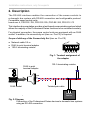
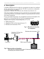
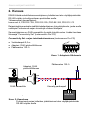
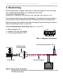
2. Description
The RS-485 interface enables the connection of the sauna controls to
a domestic bus system with RS-485 connection and configurable protocol.
Compatible sauna control units:
home.com 4, PRO D2 / D2i, PRO D3 / D3i, PRO B2 / B3, PRO C2 / C3
This interface documentation provides a text-based communication protocol which
allows the majority of the Professional Series functions to be controlled remotely.
For physical connection, the sauna control units are equipped with an RJ45
socket. In addition, the connectivity set (item no. Pro-CS) is required.
Scope of delivery of the Connectivity Set (item no. Pro-CS)
● Network cable 0.5 m
● RJ45 to print terminal adapter
●120 W terminating resistor
Fig. 1: Terminal assignment of
the adapter
RJ45 socket Twisted-pair cable
120 W terminating resistor
RJ45 to print
terminal adapter
1 2 3 4 5 6 7 8
Fig. 2: Diagram
Connection of the Professional Series devices to domestic bus systems
using an RS-485 connection
RS485
Device

EN
Installation instructions, only for experts p. 5/14
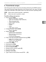
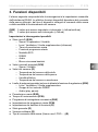
3. Functional scope
The following list includes all queries and settings allowed by the RS485 interface.
The actual functional scope depends on the sauna control unit used, the type
of devices connected to the sauna control unit and the sensor operating mode.
(R/W) Value can be set and queried (= read/write)
(R) Value can only be queried (= read)
Possible settings and queries:
● Status (on/o) (R/W)
– Sauna / evaporator / humidity
– Light / fan / auxiliary output (infrared)
– Timer for preset time
– User program function
– ECO mode
– RGBW
– Audio
– Child safety control
● Congured preset values (R/W)
– Sauna / Humidity
●Sensor values (R)
– Heater sensor temperature
– Bench sensor temperature
– Actual humidity
– Foil sensor temperature
● Power level set (only with activated dimming) (R/W)
– Light / fan / auxiliary output
– RGBW colour light group
– Audio (play, pause)
●Preset time (R/W)
●Operating time (R/W)
●Post-drying program (R/W)
●Set user program (R/W)
●Setting function selector switch (R)
●General status (R)
●Software version (R)
● Type of sauna control (Home.com4,PRO ...) (R)

Installation instructions, only for experts p. 6/14
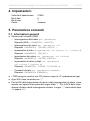
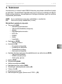
4. Settings
5. Overview of commands
5.1. General information
● Structure of commands (CMDs)
– Status queries: get (parameter)
Response (ACK): (PARAMETER) (ON/OFF);
– Value queries: get (parameter) val
Response: (PARAMETER) (VALUE)(UNIT) ;
– Status settings: set(parameter) val (value 1)...(value n)
Response: (PARAMETER) (ON/OFF);
– Value settings: set (parameter) val (value)
Response: (PARAMETER) (VALUE)(UNIT);
– Multiple value settings: set (parameter) val (value 1)(value n)
Response: (PARAMETER) (VALUE 1)(VALUE n);
– Status command: set (parameter)(command)
Response: (PARAMETER)(COMMAND);
● The CMDs are completed with CR (carriage return) and LF (line feed).
● Each ACK is ended with “;”.
●Value setting and value query ACKs feature a space before the nal “;”.
Status setting and status query ACKs feature the “;” directly after the ON or OFF.
Baud rate: 57600
Data bits: 8
Stop bits: 1
Parity: No

EN
Installation instructions, only for experts p. 7/14
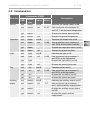
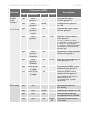
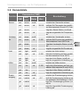
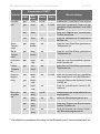
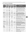
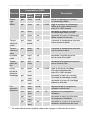
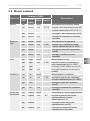
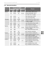
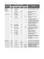
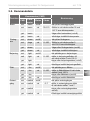
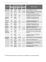
5.2. Command list
Function
Commands (CMD)
Description
CMD Param-
eter Status Value
Sauna set sauna on/o Switches the sauna heater on/o
set sauna val
30-110
Sets a selected value between 30
and 110 °C as the preset temperature
get sauna Queries the sauna status (on/o)
get sauna val Queries the preset temperature
Vaporizer set steam on/o Switches the evaporator on/o
set steam val 0-100 Sets a selected value between 0
and 100% as the preset humidity
get steam
Queries the evaporator status (on/o)
get steam val Queries the preset humidity
Light set light on/o Switches the light on/o
set light val 0-100 Sets a selected value between 0
and 100% as the light power
get light Queries the light status (on/o)
get light val Queries the preset light power
Fan set fan on/o Switches the fan on/o
set fan val 0-100 Sets a selected value between 0
and 100% as the fan power
get fan Queries the fan status (on/o)
get fan val Queries the preset fan power
Auxiliary
output
set i-switch on/o Switches the auxiliary output on/o
set i-switch val 0-7 Sets a selected value between 1
and 7 as the auxiliary output power
get i-switch Queries the auxiliary output status
(on/o)
get i-switch val Queries the preset auxiliary
output power

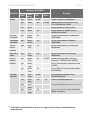
Installation instructions, only for experts p. 8/14
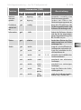
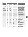
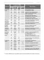
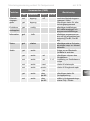
Function
Commands (CMD)
Description
CMD Param-
eter Status Value
Preset
time
get timer on/o Switches the timer for the preset
time on/o
get timer val 5-1440 Sets a selected value between
5 and 1440 minutes for the timer
for the preset time
set timer Queries the status of the timer
for the preset time (on/o)
set timer val Queries the remaining preset time
in minutes
Heater
tempera-
ture
get temp-
heater
val Queries the temperature measured
by the heater sensor
Bench
tempera-
ture
get temp-
bench
val Queries the temperature measured
by the bench sensor
Actual
humidity
get humidity val Queries the humidity measured by
the humidity sensor
Foil tem-
perature
get foil-
temp
val Queries the temperature measured
by the foil sensor
Heating
time limit
set heat-
timer
val 0-1440 Sets a selected value between 0
and 1440 minutes** for the heating
time
get heat-
timer
Queries the status of the heat timer
(on/o)
get heat-
timer
val Queries the remaining heating time
in minutes
User
programs
set user-
prog
on/o Starts/stops the selected user
program
set user-
prog
val 1-5 Selects a user program
get user-
prog
Queries the status of the user
program function
get user-
prog
val Queries the number of the user
program currently operating
** The value that can actually be set depends on the setting of the function selection switch.

EN
Installation instructions, only for experts p. 9/14
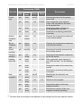
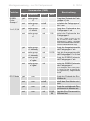
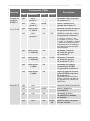
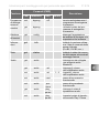
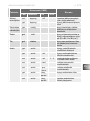
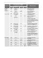
Function Commands (CMD) Description
CMD Parameter Status Value
Post-drying
program
set dryprog o Ends the post-drying
program prematurely
get dryprog Requests the status of
the post-drying program
Function
selection
switch
get cong Queries the setting of the
function selection switch
and software settings
Information get info Requests the software ver-
sion and the type of sauna
control unit connected
(Pro-B2, Pro-B3, etc.)
Status get status Requests the status of
the sauna control unit
and any error messages
Audio get audio Queries whether
a Bluetooth audio
source is connected
get audio val Queries the volume of
the audio amplier
set audio val 1 - 4 Adjusts the volume of
the audio amplier
set audio next Changes to the next
audio track
set audio previ-
ous
Changes to the previous
audio track
get audio play_
pause
Queries the status of audio
playback
set audio play_
pause
Sets the audio playback
status play / pause

Installation instructions, only for experts p. 10/14
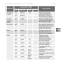
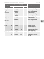
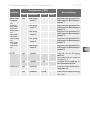
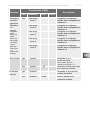
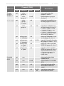
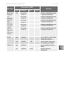
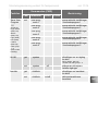
Function Commands (CMD) Description
CMD Parameter Status Value
RGBW
Color
Group n*
*n= 1,2,3,4
get color-
group-n*
Queries the status
of color group n*)
set color-
group-n*
on/o Switches color group n*
on / o
get Color-
group-n*
mode
val Queries the colour mode
of color group n*
set color-
group-n*
val 0-8 Sets the colour mode of
color group n*
0 = red, 1 = yellow, 2 = green,
3 = turquoise, 4 = blue, 5 = purple,
6 = white, 7 = colour gradient,
8 = external -> Output via external
control panel or colour mixer via
Bluetooth app.
get color-
group-n*
intensity
val
Queries the output intensity
of the color group n*
set color-
group-n*
intensity
val 5-100 Sets the output intensity of
color group n* in %
get color-group-
n*-rgbw
val Queries the RGBW colour
values of color group n*
set color-group-
n*-rgbw
val Sets the RGBW colour
values of color group n*
(only available if color-group-n*-
mode val is set to 8)
(rrr ggg bbb www) - possible
values 0-255
ECO mode get eco Queries the status of
Eco mode
set eco on/o
Switches Eco mode on / o
get eco val Queries the remaining
eco-pause time in minutes
set eco val 20,40,
60
Sets the Eco pause time
in minutes

EN
Installation instructions, only for experts p. 11/14
Function Commands (CMD) Description
CMD Parameter Status Value
Save User
Program
1-5
Saved settings:
Sauna
(state, val)
Steam
(state, val)
Light (state)
Fan (state)
I-switch
(state val)
Color-group
1 – 4
(state, mode,
intensity)
set user-prog-
save-1
Saves current settings
in user program 1
user-prog-
save-2
Saves current settings
in user program 2
user-prog-
save-3
Saves current settings
in user program 3
user-prog-
save-4
Saves current settings
in user program 4
user-prog-
save-5
Saves current settings
in user program 5
All O get system Queries whether
an output is active
sauna, steam, light, fan,
i-switch and color-group 1 -4
set system o Switches o all outputs
on the control unit
Child-Lock get childlock Queries if the child lock
is active
set childlock on/o Switches the child lock
on / o

Installation instructions, only for experts p. 12/14
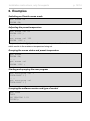
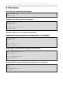
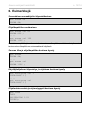
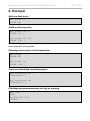
6. Examples
Switching on Finnish sauna mode
set sauna on
SAUNA ON;
set sauna val 85
SAUNA 85C ;
....
set sauna val 300
SAUNA 110C ;
Adjusting the preset temperature
The preset value is slightly above the maximum temperature that can be set,
which results in the maximum temperature being set.
get sauna
SAUNA ON;
....
get sauna val
SAUNA 110C ;
Querying the sauna status and preset temperature
set user-prog val 3
USER-PROG 3 ;
....
get user-prog val
USER-PROG 3 ;
Starting and querying the user program
get info
INFO
SW VERSION 1.03
TYPEC3;
Querying the software version and type of control

EN
Installation instructions, only for experts p. 13/14
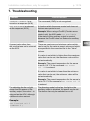
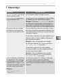
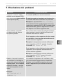
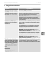
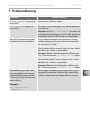
Problem Cause/solution
UNKNOWN COMMAND is re-
turned as a response (ACK)
The command (CMD) is not recognized.
NOT AVAILABLE is returned
as the response (ACK)
A function which the sauna control unit does not
feature was queried or set.
Example: When using a Pro-B2 (Finnish sauna
control unit), the ACK reads not available
if the status of the auxiliary output is queried,
because the Pro-B2 does not feature an auxiliary
output.
A preset value other than
the one that was set is returned
as the ACK.
There are maximum and minimum values which
can be set for the various preset values and which
are specied in the command list in the “Value”
column.
If a value is set which is higher than the maximum
value that can be set, the maximum value will be
set automatically.
Example: The preset temperature for the sauna
is set to 110 °C if the command set sauna
val 120 is entered.
If a value is set which is lower than the minimum
value that can be set, the minimum value will be
set automatically.
Example: The preset temperature for the sauna is
set to 30 °C if the command set sauna val 10
is entered.
For adjusting the fan or light
power and the power of the
auxiliary output, the value 0 is
returned as the ACK, although
a dierent value was set.
Example:
set i-switch val 2
I-SWITCH 0 ;
The dimming mode for the fan, the light or the
auxiliary output is disabled. No power can be set.
The device can only be switched on or o.
7. Troubleshooting

Installation instructions, only for experts p. 14/14
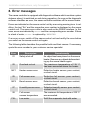
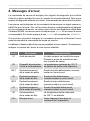
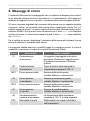
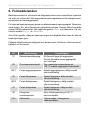
8. Error messages
The sauna controller is equipped with diagnostic software which monitors system
statuses when it is switched on and during operation. As soon as the diagnostic
software identies an error, the sauna controller switches o the sauna heater.
Errors are indicated on the sauna control unit by a recurring warning tone. In ad-
dition, the text “Err” and the respective error number is displayed on the sauna
control unit. The same error code is also used on the RS485 interface. In this
case, errors are indicated by error and the corresponding error number. If there
is a lack of water, error is replaced by WARNING.
If an error occurs, switch o the sauna control unit and rectify the error before
you switch on the sauna control unit again.
The following table describes the possible faults and their causes. If necessary,
quote the error number to your customer service specialist.
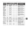
Error Description Cause/remedy
01 Safety shut-o An object has been placed on the sauna
heater. Remove any objects before start-
ing up the sauna heater again.
02 Overheat cut-out The maximum temperature of 139 °C
has been exceeded above the heater.
04F1 Heater sensor error Defective heater sensor, poor contact,
or short circuit.
05 Foil sensor error Defective foil sensor, poor contact,
or short circuit.
06F2 Bench sensor error Defective bench sensor, poor contact,
or short circuit.
07 Humidity sensor error Defective humidity sensor, poor contact,
or short circuit
08 Foil sensor
excess temperature
The maximum foil temperature of 100 °C
was exceeded.
FILL Low water Rell the evaporator tank with water

Version 08/22 Ident-Nr. 1-027-269
Schnittstellen- Dokumentation
Deutsch
DE
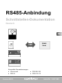
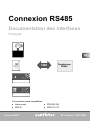
RS485-Anbindung
Kompatible Saunasteuerungen:
CMD RS485
Gerät
●PRO B2 / B3
●PRO C2 / C3
●Home.com4
●PRO D

Inhaltsverzeichnis
1. Wichtige Sicherheitshinweise 3
2. Beschreibung 4
3. Funktionsumfang 5
4. Settings 6
5. Kommandoübersicht 6
5.1. Allgemeines 6
5.2. Komandoliste 7
6. Beispiele 12
7. Problemlösung 13
8. Fehlermeldungen 14

DE
Montageanweisung – nur für Fachpersonal S. 3/14
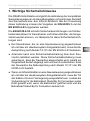
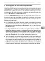
1. Wichtige Sicherheitshinweise
Die RS485-Schnittstelle ermöglicht die Anbindung der kompatiblen
Saunasteuerungen an ein Haus-Bussystem und somit einen Fernstart
des Saunaofens bzw. des Infrarot-Strahlers. Bei der Umsetzung
dieser Anbindung müssen die Vorgaben der EN 60335-1 und der
EN 60335-2-53 eingehalten werden.
Die EN 60335-2-53 schreibt Sicherheitseinrichtungen und Sicher-
heitsmaßnahmen für Saunaheizer und Infrarot-Emitter, die fernge-
startet werden können, vor. Beispiele für diese Sicherheitseinrich-
tungen sind:
●Der Saunaheizer, der an eine Saunasteuerung angeschlossen
ist und über ein Hausbussystem ferngestartet wird, muss die Ab-
deckprüfung nach Absatz 19.101 der EN 60335-2-53 bestehen.
●Alternativ kann eine Sicherheitsabschaltung über dem Sau-
naofen installiert werden. Diese Sicherheitsabschaltung muss
garantieren, dass der Saunaofen abgeschaltet wird, sobald ein
Gegenstand darauf abgelegt wird und somit sicherstellen, dass
der Saunaofen die Abdeckprüfung nach Absatz 19.101 der EN
60335-2-53 besteht.
●Wenn ein Infrarot-Emitter an eine Saunasteuerung angeschlossen
ist und über ein Hausbussystem ferngestartet wird, muss die Tür
der Kabine mit einer Verriegelung ausgestattet sein, sodass die
Vorbereitung für die Betriebsart Stand-By für Fernwirken außer
Kraft gesetzt wird, wenn die Kabinentür geönet wird und die
Betriebsart Stand-By für Fernwirken aktiviert ist.

Montageanweisung – nur für Fachpersonal S. 4/14
RS485
1
2 GND
3
4 B
5 A
6
7 GND
8
AB
RS485
Gerät
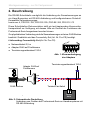
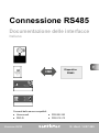
2. Beschreibung
Die RS485-Schnittstelle ermöglicht die Anbindung der Saunsteuerungen an
ein Haus-Bussystem mit RS-485-Anbindung und kongurierbarem Protokoll.
Kompatible Saunasteuerungen:
home.com 4, PRO D2 / D2i, PRO D3 / D3i, PRO B2 / B3, PRO C2 / C3
Diese Schnittstellen-Dokumentation stellt ein text-basierendes Kommunika-
tionsprotokoll zur Verfügung, mit dessen Hilfe ein Großteil der Funktionen der
Professional-Serie ferngesteuert werden können.
Zur physikalischen Verbindung sind die Saunasteuerungen mit einer RJ45-Buchse
bestückt. Zusätzlich wird das Connectivity Set (Art. Nr. Pro-CS) benötigt.
Lieferumfang Connectivitiy Set (Art. Nr. Pro-CS)
● Netzwerkkabel 0,5 m
● Adapter RJ45 auf Printklemme
●Terminierungswiderstand 120 W
Abb. 1: Klemmenbelegung
des Adapters
RJ45-Buchse Twisted-Pair-Kabel
Terminierungswiderstand 120 W
Adapter RJ45 auf
Printklemme
1 2 3 4 5 6 7 8
Abb. 2: Schematische Darstellung
Anbindung von Geräten der Professional-Serie an Hausbussysteme mit
RS-485-Anbindung

DE
Montageanweisung – nur für Fachpersonal S. 5/14
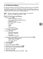
3. Funktionsumfang
Die folgende Aufzählung umfasst alle Abfragen und Einstellungen, die die RS485-
Schnittstelle ermöglicht. Der tatsächliche Funktionsumfang hängt von der ver-
wendeten Saunasteuerung, von der Art der Geräte, die an der Saunasteuerung
angeschlossen sind, und von der Fühlerbetriebsart ab.
(R/W) Wert kann eingestellt und abgefragt werden (= read/write)
(R) Wert kann nur abgefragt werden (= read)
Mögliche Einstellungen und Abfragen:
● Status (on/o) (R/W)
– Sauna / Verdampfer / Feuchte
– Licht / Lüfter / Zusatzausgang (Infrarot)
– Vorwahlzeit-Timer
– Benutzerprogramm-Funktion
– ECO-Mode
– RGBW
– Audio
– Kindersicherung
●Eingestellte Sollwerte (R/W)
– Sauna / Feuchte
● Fühler-Werte (R)
– Ofenfühler-Temperatur
– Bankfühler-Temperatur
– Ist-Feuchte
– Folienfühler-Temperatur
● Eingestellte Leistungsstufe (nur bei aktivierter Dimmfunktion) (R/W)
– Licht / Lüfter / Zusatzausgang
– RGBW Farblicht Gruppe
– Audio (play, pause)
●Vorwahlzeit (R/W)
●Laufzeit (R/W)
● Nachtrockenprogramm (R/W)
●Einstellung der Benutzerprogramme (R/W)
● Einstellung der Funktionswahlschalter (R)
●Allgemeiner Status (R)
●Software-Version (R)
● Art der Saunsteuerung (Home.com4,PRO ...) (R)

Montageanweisung – nur für Fachpersonal S. 6/14
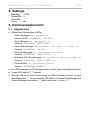
4. Settings
5. Kommandoübersicht
5.1. Allgemeines
● Aufbau der Kommandos (CMDs)
– Status-Abfragen: get (parameter)
Antwort (ACK): (PARAMETER) (ON/OFF);
– Wert-Abfragen: get (parameter) val
Antwort: (PARAMETER) (WERT)(UNIT) ;
– Status-Einstellungen: set(parameter) val (Wert 1)...(Wert n)
Antwort: (PARAMETER) (ON/OFF);
– Wert-Einstellungen: set (parameter) val (Wert)
Antwort: (PARAMETER) (WERT)(UNIT);
– Mehrfach-Wert-Einstellungen: set (parameter) val (Wert1)(Wert n)
Antwort: (PARAMETER) (WERT 1)(WERT n);
– Status-Befehl: set (parameter)(befehl)
Antwort: (PARAMETER)(BEFEHL);
●Die CMDs werden mit CR (carriage return) und LF (line feed) abgeschlossen.
● Jedes ACK wird mit ";" beendet.
●Bei den ACKs von Wert-Einstellungen und Wert-Abfragen kommt vor dem
abschließenden ";" ein Leerzeichen. Bei ACKs von Status-Einstellungen und
Status-Abfragen kommt das ";" gleich nach dem ON oder OFF.
Baudrate: 57600
Daten-Bits: 8
Stop-Bits: 1
Parity: No
Sidan laddas...
Sidan laddas...
Sidan laddas...
Sidan laddas...
Sidan laddas...
Sidan laddas...
Sidan laddas...
Sidan laddas...
Sidan laddas...
Sidan laddas...
Sidan laddas...
Sidan laddas...
Sidan laddas...
Sidan laddas...
Sidan laddas...
Sidan laddas...
Sidan laddas...
Sidan laddas...
Sidan laddas...
Sidan laddas...
Sidan laddas...
Sidan laddas...
Sidan laddas...
Sidan laddas...
Sidan laddas...
Sidan laddas...
Sidan laddas...
Sidan laddas...
Sidan laddas...
Sidan laddas...
Sidan laddas...
Sidan laddas...
Sidan laddas...
Sidan laddas...
Sidan laddas...
Sidan laddas...
Sidan laddas...
Sidan laddas...
Sidan laddas...
Sidan laddas...
Sidan laddas...
Sidan laddas...
Sidan laddas...
Sidan laddas...
Sidan laddas...
Sidan laddas...
Sidan laddas...
Sidan laddas...
Sidan laddas...
Sidan laddas...
Sidan laddas...
Sidan laddas...
Sidan laddas...
Sidan laddas...
Sidan laddas...
Sidan laddas...
Sidan laddas...
Sidan laddas...
Sidan laddas...
Sidan laddas...
Sidan laddas...
Sidan laddas...
Sidan laddas...
Sidan laddas...
Sidan laddas...
Sidan laddas...
Sidan laddas...
Sidan laddas...
-
 1
1
-
 2
2
-
 3
3
-
 4
4
-
 5
5
-
 6
6
-
 7
7
-
 8
8
-
 9
9
-
 10
10
-
 11
11
-
 12
12
-
 13
13
-
 14
14
-
 15
15
-
 16
16
-
 17
17
-
 18
18
-
 19
19
-
 20
20
-
 21
21
-
 22
22
-
 23
23
-
 24
24
-
 25
25
-
 26
26
-
 27
27
-
 28
28
-
 29
29
-
 30
30
-
 31
31
-
 32
32
-
 33
33
-
 34
34
-
 35
35
-
 36
36
-
 37
37
-
 38
38
-
 39
39
-
 40
40
-
 41
41
-
 42
42
-
 43
43
-
 44
44
-
 45
45
-
 46
46
-
 47
47
-
 48
48
-
 49
49
-
 50
50
-
 51
51
-
 52
52
-
 53
53
-
 54
54
-
 55
55
-
 56
56
-
 57
57
-
 58
58
-
 59
59
-
 60
60
-
 61
61
-
 62
62
-
 63
63
-
 64
64
-
 65
65
-
 66
66
-
 67
67
-
 68
68
-
 69
69
-
 70
70
-
 71
71
-
 72
72
-
 73
73
-
 74
74
-
 75
75
-
 76
76
-
 77
77
-
 78
78
-
 79
79
-
 80
80
-
 81
81
-
 82
82
-
 83
83
-
 84
84
-
 85
85
-
 86
86
-
 87
87
-
 88
88


Sentiotec RS485 Connection Användarmanual
- Typ
- Användarmanual
på andra språk
- italiano: Sentiotec RS485 Connection Manuale utente
- français: Sentiotec RS485 Connection Manuel utilisateur
- English: Sentiotec RS485 Connection User manual
Relaterade papper
-
Sentiotec Pro D Användarmanual
-
-
-
-
-
-
-
-
-