
Version 10/23 Ident no. 1-053-313
EN
DE
FR
IT
NL
SV
INSTALLATION AND OPERATING INSTRUCTIONS
English
FI
CS
PL
MySentio WiFi
1-053-313 / S-WIFI01

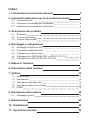
Table of Contents
1. About this instruction manual 3
2. Important information for your safety 3
2.1. Intended use 3
2.2. Safety information for the installer 4
2.3. Safety information for the user 4
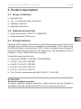
3. Product description 5
3.1. Scope of delivery 5
3.2. Optional accessories 5
3.3. Product features 5
4. Installation and connection 6
4.1. MySentio WiFi installation 6
4.2. Connection MySentio WiFi 7
4.3. Connection to home.com4 7
4.4. Connection to PRO B (B2, B3) und PRO C (C2, C3) 7
4.5. Connection to PRO D (D2, D2I, D3, D3I) 8
5. Commissioning 8
6. Overview of functions 11
7. Operation 12
7.1. Home menu 12
7.2. Settings 14
7.3. Device settings 15
7.4. Coloured light settings 16
7.5. Prole 18
8. Troubleshooting 19
8.1. Error messages 19
9. Maintenance 20
10. Disposal 20
11. Technical data 20

EN
Instructions for installation and use p. 3/20
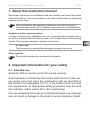
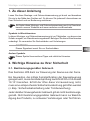
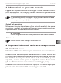
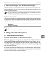
1. About this instruction manual
Read these instructions for installation and use carefully and keep them within
reach of the device. This ensures that you can refer to information on safety and
operation at any time.
Symbols used for warning notices
In these instructions for installation and use, a warning notice located next to
an activity indicates that this activity poses a risk. Always observe the warning
notices. This prevents damage to property and injuries.
ATTENTION!
This keyword is a warning that damage to property can occur.
Other symbols
This symbol indicates tips and useful information.
These installation and operating instructions can also be found in
the downloads section of our website: www.sentiotec.com/downloads.
2. Important information for your safety
2.1. Intended use
Sentiotec WiFi is used to control the sauna remotely.
A sauna heater controlled by the remote start function of the sau-
na control unit must pass the combustion test as specified in
EN 60335-2-53 paragraph 19.101. If the heater does not meet
this requirement, an appropriate safety precaution must be used
(forexample:safetyswitch-oordoormonitoring)
Any use exceeding this scope is considered improper use. Improper
use can result in damage to the product, severe injuries or death.

Instructions for installation and use p. 4/20
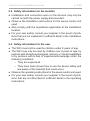
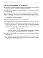
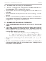
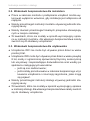
2.2. Safety information for the installer
●Installation and connection work on the devices may only be
carried out with the power supply disconnected.
●Observe the installation instructions for the sauna control unit
used.
●Also comply with the regulations applicable at the installation
location.
●For your own safety, consult your supplier in the event of prob-
lemsthatarenotexplainedinsucientdetailintheinstallation
instructions.
2.3. Safety information for the user
●The WiFi must not be used by children under 8 years of age.
●The WiFi may only be used by children over 8 years of age, by
persons with limited psychological, sensory or mental capabilities
or by persons with a lack of experience/knowledge under the
following conditions:
– They are supervised.
– They have been shown how to use the device safely and
are aware of the hazards that could occur.
●Observe the operating instructions for the sauna control unit used.
●For your own safety, consult your supplier in the event of prob-
lemsthatarenotdescribedinsucientdetailintheoperating
instructions.

EN
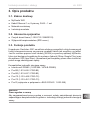
Instructions for installation and use p. 5/20
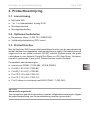
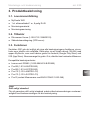
3. Product description
3.1. Scope of delivery
●MySentio WiFi
●1 pc. 1 m Ethernet cable, 8-pin RJ45
●Installation material
●Assembly instructions
3.2. Optional accessories
●Home door sensor (1-052-723 / SAB00103)
●Safety shutdown (SFE-xxxxx)
3.3. Product features
Sentiotec WiFi enables the functions of all existing sauna control units to be
operated using devices such as smartphones and tablets. This is done using
the MySentio app in a local network (WiFi), which is available free of charge for
Android (Google Play Store) and for iOS (App Store). The subscription is free of
charge for 3 years, after which fees may apply.
Compatible sauna control units:
●home.com4 RS485 (1-052-984 / HC4-B-RS485)
●Pro B2 (1-015-455 / PRO-B2)
●Pro B3 (1-015-457 / PRO-B3)
●Pro C2 (1-015-448 / PRO-C2)
●Pro C3 (1-015-451 / PRO-C3)
●Pro D (only in combination with BUS-CON-D / 1-053-348)
ATTENTION!
Standard-compliant operation
To ensure standard-compliant operation, safety devices must be installed in
accordance with the operating instructions for your sauna control unit.

Instructions for installation and use p. 6/20
ATTENTION!
Interference can impair signal transmission
●Route all data cables separately from other mains cables and control cables.
●Protect cables with only one layer of insulation by using a conduit (double
insulation).
ATTENTION!
Damage to the device!
Installation of the app and input of the settings (see “6. Overview of functions” and
“7. Operation”) must be completed before the sauna control unit is switched on.
30
27.5
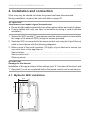
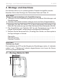
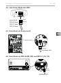
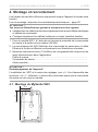
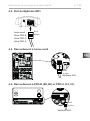
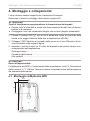
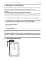
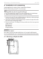
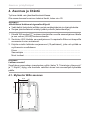
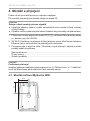
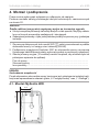
4. Installation and connection
Work may only be carried out when the power has been disconnected.
During installation, observe the technical data on page 20.
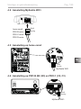
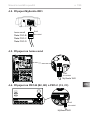
1. Secure the WiFi module 1 somewhere near the sauna control unit and within
the range of its network (WiFi) using the screws provided.
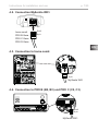
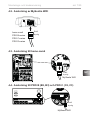
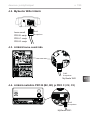
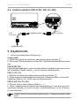
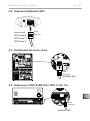
2. Sentiotec WiFi is connected to the sauna control unit using the 8-pin Ethernet
cable in accordance with the following diagrams:
3. Make a note of the serial numbers (10 digits) of your devices to ensure you
can enter them in the app later on.
Sauna heater ................................................................................................
Sauna control unit ........................................................................................
Other products ..............................................................................................
4.1. MySentio WiFi installation

EN
Instructions for installation and use p. 7/20
156
193
238
156
238
193
193
156
193
238
156
238
193
193
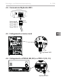
MySentio WiFi
STB
Auto
FF
rd wt bk
home.com4
PRO B-Serie
PRO C-Serie
PRO D-Serie
STB
Auto
FF
rd wt bk
RJ45
8 pin
RJ45
8 pin
STB
Auto
FF
rd wt bk
MySentio WiFi
RJ45
8 pin
4.2. Connection MySentio WiFi
4.3. Connection to home.com4
4.4. Connection to PRO B (B2, B3) und PRO C (C2, C3)

Instructions for installation and use p. 8/20
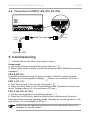
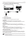
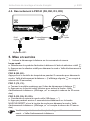
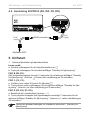
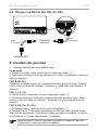
5. Commissioning
1. Activate the remote start on the sauna control.
home.com4:
a. Use rotary selector to select the remote start icon.
b.Pressrotaryselectorbrieytostarttheoperatingmode“Standbyforremote
operation”
PRO B (B2, B3):
Press the temperature knob for three seconds to start the operating mode
“Standby for remote operation”(display ashesorCountdownof30sec.)
PRO C (C2, C3):
a. Turn the top knob to the remote start symbol
b. Press the lower knob to start the operating mode “Standby for remote ope-
ration” (display shows „on“ or countdown of 30 sec.)
PRO D (D2, D2i, D3, D3i):
a. Control unit at standby-mode (display shows „---“)
b.PresstheOn/Obuttonandthemodebuttonsimultaneouslyforabout
three seconds to start the operating mode “Standby for remote operation” (dis-
play shows „rc“ or countdown of 30 sec.)
Please note the operating instructions for the respective control unit -
“Standby for remote control”
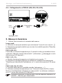
MySentio WiFi
BUS-Converter
STB
Auto
FF
rd wt bk
STB
Auto
FF
rd wt bk
STB
Auto
FF
rd wt bk
STB
Auto
FF
rd wt bk
RJ12
6 pin
RJ45
8 pin
4.5. Connection to PRO D (D2, D2I, D3, D3I)

EN
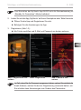
Instructions for installation and use p. 9/20
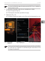
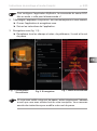
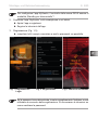
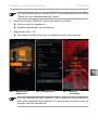
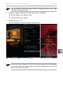
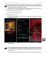
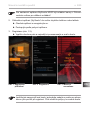
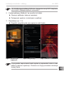
Fig. 1 Signing up/
logging in Fig. 2 Signing up Fig. 3 World of sensations
In case you have forgotten your password, simply enter the email address
you used when you registered. You will then be given instructions on how
to change the password.
To set up the MySentio app, the sauna control MUST be in “standby for
remote control” mode!
2. Download the “MySentio” app onto your smartphone or tablet
►Open the app and sign up.
►Following the instructions provided in the app.
3. Signing up (Fig. 1–3):
►Completealleldsandmakeanoteoftheemailandpasswordyouuse.

Instructions for installation and use p. 10/20
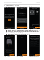
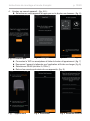
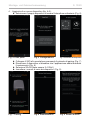
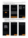
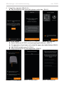
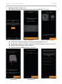
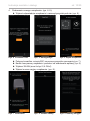
Fig. 4 First steps Fig. 5 Conguration Fig. 6 Select device
Fig. 7 Pairing Fig. 8 Rename Fig. 9 Serial numbers
4. Add a new device: (Fig. 4–5):
►Select your device and tap the switch below it. (Fig. 6)
►Connect the WiFi to the smartphone by pressing the pairing button.(Fig. 7)
► Renamethedeviceandwaituntiltheapphasnishedloading.(Fig.8)
►Select WLAN (must be 2.4 GHz!)
►Enter the serial numbers of your devices. (Fig. 9)

EN
Instructions for installation and use p. 11/20
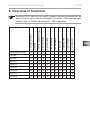
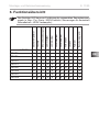
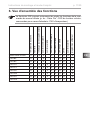
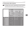
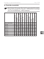
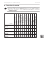
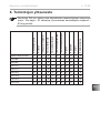
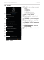
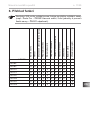
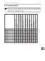
6. Overview of functions
Sentiotec WiFi can only be used to control functions provided by the
sauna control unit in use (for example: Pro-series – NO coloured light,
control units for Finnish sauna mode – NO evaporator)
Sauna temperature
Humidity
Infrared (additional output)
Light switchable
Light dimmable
Fan switchable
Fan dimmable
Preset time
Operating time
Coloured light
User program
home.com4 RS485
XXXX X XXXX
PRO B2
X X X X
PRO B3
X X X X X
PRO C2
X XXXXXXX X
PRO C3
XXXXXXXXX X
PRO D2
X XXXXXX X
PRO D2i
X XXXXXXX X
PRO D3
XX XXXXXX X
PRO D3i
XXXXXXXXX X

Instructions for installation and use p. 12/20
8
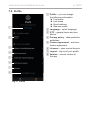
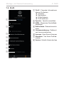
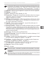
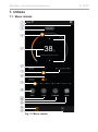
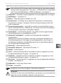
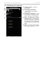
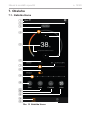
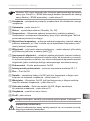
Fig. 10 Home menu
7. Operation
2
3
7.1. Home menu
c
7
9
1
a
b
6
4
5
f
e
d

EN
Instructions for installation and use p. 13/20
DANGER!
Makesurethatnoammableobjectsareeverleftonthesaunaheater
when the sauna cabin is put into operation.
1 Devices – switch between devices or add new devices.
2 Settings – see page 14
3 Status–statusdisplay(standby,on,o)
4 Temperature – setting for the preferred temperature (set point)
Increase/decrease temperature using arrow up/down or
bymovingtheameinthecircle
5 Temperature display – shows the selected temperature (set point) when
entering the settings, changes to displaying the measured temperature
(actual value) after 3 sec.
6 Humidity–combimodeon/o–canonlybeswitchedonifthesauna
heater is switched on (see b)
7 Intensity of humidity – setting for the preferred humidity (set point)
The maximum humidity set point will depend on the sauna temperature.
The higher the sauna temperature, the lower the maximum humidity value
that can be set (see the operating instructions for the sauna control unit in use)
8 Infrared – infraredlampon/o
9 Intensity of infrared – IR lamp dimmer levels 1–7
a Heater–heateron/o
b Light–cabinlighton/o,ifdimmablepressandholdtoenterdevice
settings – see page 15
b Fan–fanon/o,ifvariablepressandholdtoenterdevicesettings
– see page 15
d Coloured light–colouredlighton/o,pressandholdtoenterdevice
settings – see page 15
e Devices – back to the Home menu
f Prole – see page
Sentiotec WiFi can only be used to control functions provided by the
sauna control unit in use (for example: Pro-series – NO coloured light,
control units for Finnish sauna operation – NO evaporator) – see page 11
Press and hold: press the symbol and hold it for 3 seconds

Instructions for installation and use p. 14/20
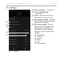
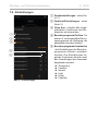
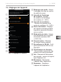
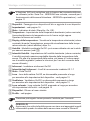
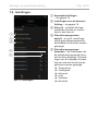
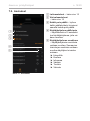
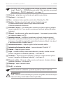
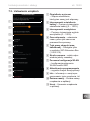
Fig. 11 Settings
1
2
4
5
1 Device settings – see page 15
2 Colour light settings
– see page 16
3 All o–switchesoallfunc-
tions and consumers at once.
4 User program on/o – there are
5 preset user programs available,
which can be changed.
5 Edit user program – the set-
tings in the user programs can
be changed. The settings for
the following functions can be
changed to suit the user’s pref-
erences.
►Temperature
►Humidity
►Infrared
►Light
►Fan
►Coloured light
7.2. Settings
3

EN
Instructions for installation and use p. 15/20
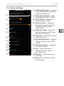
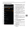
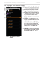
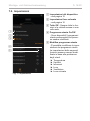
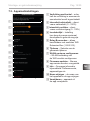
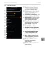
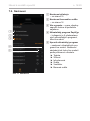
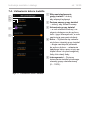
Fig. 12 Device settings
1
2
3
4
5
6
7
8
7.3. Device settings
9
a
b
1 Lighting with heater – switches
on the lighting when the sauna
heater is switched on
2 Cabin light intensity – cabin
light dimming levels (0–100%)
3 Fan intensity – variable fan
output levels (0–100%)
4 Switch-on time – setting for
the maximum period for which
the sauna should operate
continuously.
5 Relay box mode – Only avail-
able with sentiotec WiFi Exten-
sion Box (1-053-315).
6 Time zone – selection of the rel-
evant time zone
7 Recongure WLAN–congure
WLANconnectionoftheWi
module
8 Firmware updates – suggests
new app versions.
9 Info – query information,
such as: software version,
device type, etc.
a Rename – rename the device
in the app.
b Remove – remove the device
from the app.

Instructions for installation and use p. 16/20
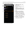
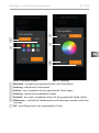
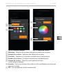
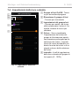
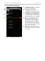
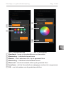
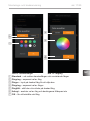
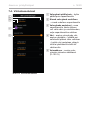
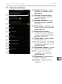
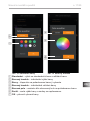
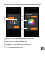
Fig. 13 Coloured light settings
7.4. Coloured light settings
1
3
1 Light group on/o – tap to
switchon/o
2 Rename light group – tap to
rename
3 Light group settings – tap to
open, then select from colour
and intensity, and tap again to
close
4 Colour – colour setting for
the light group that is open is
displayed – press and hold to
select colours – setting for the
preferred colour entered using
the colour wheel or an individual
colour, or colour rotation
5 Intensity – coloured light dim-
ming levels for the light group
that is open (0–100%)
4
2
5

EN
Instructions for installation and use p. 17/20
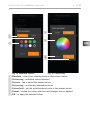
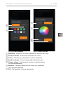
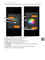
1
3
2
4
5
6
7
1 Standard – select from standard colours and colour rotation
2 Colour ring – individual colour selection
3 Colours – tap to select the desired colour
4 Colour ring – individually selectable colours
5 Colour eld – set the white-bordered circle to the desired colour
6 Cancel – closes the colour selection and changes are not applied
7 OK – to apply the selected colour
Fig. 14 Standard colours Fig. 15 Colour ring

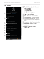
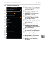
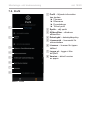
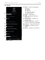
Instructions for installation and use p. 18/20
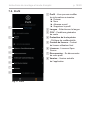
1 Prole – you can change
the following information:
►First name
►Last name
►Email address
► Removeprole
2 Language – select language
3 GTC – general terms and con-
ditions
4 Privacy policy – data protection
guidelines
5 Licence agreement – end user
licence agreement
6
Licences – open source licences
7 Logout–logoutofyourprole
8 Version – current version of
the app
Fig. 16 Prole
1
2
3
4
5
6
7.5. Prole
7
8
Fig. 17 Prole

EN
Instructions for installation and use p. 19/20
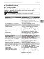
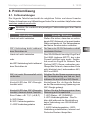
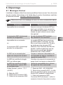
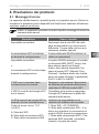
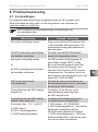
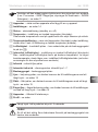
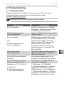
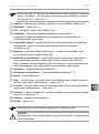
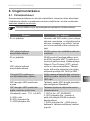
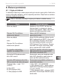
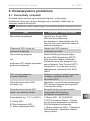
8. Troubleshooting
8.1. Error messages
The following table describes the possible faults and their causes. Further infor-
mation and assistance can be found in the sentiotec help centre at:
sentiotec.zendesk.com/hc/de
Description Cause/remedy
Cannot connect Make sure that the WiFi network to be
connectedissucientlystrong.
The network name cannot contain any
special characters.
WiFi connection is interrupted
during setup
The name of the WiFi network
contains inadmissible characters.
Cannot connect
or
WiFi connection terminates
during setup
The WiFi module requires access to
port 8883 (secure MQTT), which must
beopenedintherewall.Additional-
ly, there must be access for Network
Time Protocol (NTP) servers. Also
check that other ports are not blocked,
especially 443, 8443 and 8883.
WiFi is not connected
after power failure
Switch the power supply of the sauna
controlunitoandonagain,check
the LED on the WiFi module.
Control LED of the WiFi dongle
does not light up
Check whether power is reaching
the WiFi dongle via the socket on
the sauna control unit.
Control LED of the WiFi dongle
lights up, but still no function
Check that software version of
your controller is compatible.
Error codes: e.g.: 7,2,1 (=A,B,C)
A: WiFi status
B: WiFi connection status
C: AWS connection status
7: WiFi status – AP_RUNNING
2: WiFi connection status – the phone
is not maintaining a connection to
the WiFi module.
1: AWS connection status – AWS con-
nection interrupted, check the internet
and ports of the router.
Also note the error messages of your sauna control unit.

Instructions for installation and use p. 20/20
●Dispose of packaging materials in accordance with the applicable
waste disposal regulations.
●Used devices contain reusable materials as well as hazardous
substances. Therefore, do not dispose of your used device with
household waste, but do so in accordance with the locally appli-
cable regulations.
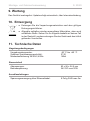
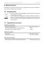
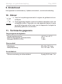
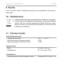
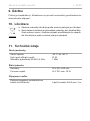
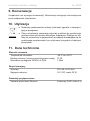
9. Maintenance
The device is maintenance-free. An internet connection is used to update it
automatically.
10. Disposal
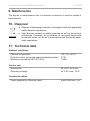
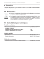
11. Technical data
Ambient conditions
Ambient temperature: -20 °C to +40 °C
Protection class (protected against splashing water): IP 20
Minimum requirement WiFi 2.4 GHz: 1 Mbit
Control unit
Dimensions: 83 x 56 x 24.5 mm
Operating voltage: 24 V DC max. 10 W
Connection cables
Power supplied by Ethernet cable: 8-pin RJ45 max. 3 m
Sidan laddas...
Sidan laddas...
Sidan laddas...
Sidan laddas...
Sidan laddas...
Sidan laddas...
Sidan laddas...
Sidan laddas...
Sidan laddas...
Sidan laddas...
Sidan laddas...
Sidan laddas...
Sidan laddas...
Sidan laddas...
Sidan laddas...
Sidan laddas...
Sidan laddas...
Sidan laddas...
Sidan laddas...
Sidan laddas...
Sidan laddas...
Sidan laddas...
Sidan laddas...
Sidan laddas...
Sidan laddas...
Sidan laddas...
Sidan laddas...
Sidan laddas...
Sidan laddas...
Sidan laddas...
Sidan laddas...
Sidan laddas...
Sidan laddas...
Sidan laddas...
Sidan laddas...
Sidan laddas...
Sidan laddas...
Sidan laddas...
Sidan laddas...
Sidan laddas...
Sidan laddas...
Sidan laddas...
Sidan laddas...
Sidan laddas...
Sidan laddas...
Sidan laddas...
Sidan laddas...
Sidan laddas...
Sidan laddas...
Sidan laddas...
Sidan laddas...
Sidan laddas...
Sidan laddas...
Sidan laddas...
Sidan laddas...
Sidan laddas...
Sidan laddas...
Sidan laddas...
Sidan laddas...
Sidan laddas...
Sidan laddas...
Sidan laddas...
Sidan laddas...
Sidan laddas...
Sidan laddas...
Sidan laddas...
Sidan laddas...
Sidan laddas...
Sidan laddas...
Sidan laddas...
Sidan laddas...
Sidan laddas...
Sidan laddas...
Sidan laddas...
Sidan laddas...
Sidan laddas...
Sidan laddas...
Sidan laddas...
Sidan laddas...
Sidan laddas...
Sidan laddas...
Sidan laddas...
Sidan laddas...
Sidan laddas...
Sidan laddas...
Sidan laddas...
Sidan laddas...
Sidan laddas...
Sidan laddas...
Sidan laddas...
Sidan laddas...
Sidan laddas...
Sidan laddas...
Sidan laddas...
Sidan laddas...
Sidan laddas...
Sidan laddas...
Sidan laddas...
Sidan laddas...
Sidan laddas...
Sidan laddas...
Sidan laddas...
Sidan laddas...
Sidan laddas...
Sidan laddas...
Sidan laddas...
Sidan laddas...
Sidan laddas...
Sidan laddas...
Sidan laddas...
Sidan laddas...
Sidan laddas...
Sidan laddas...
Sidan laddas...
Sidan laddas...
Sidan laddas...
Sidan laddas...
Sidan laddas...
Sidan laddas...
Sidan laddas...
Sidan laddas...
Sidan laddas...
Sidan laddas...
Sidan laddas...
Sidan laddas...
Sidan laddas...
Sidan laddas...
Sidan laddas...
Sidan laddas...
Sidan laddas...
Sidan laddas...
Sidan laddas...
Sidan laddas...
Sidan laddas...
Sidan laddas...
Sidan laddas...
Sidan laddas...
Sidan laddas...
Sidan laddas...
Sidan laddas...
Sidan laddas...
Sidan laddas...
Sidan laddas...
Sidan laddas...
Sidan laddas...
Sidan laddas...
Sidan laddas...
Sidan laddas...
Sidan laddas...
Sidan laddas...
Sidan laddas...
Sidan laddas...
Sidan laddas...
Sidan laddas...
Sidan laddas...
Sidan laddas...
Sidan laddas...
Sidan laddas...
Sidan laddas...
Sidan laddas...
Sidan laddas...
-
 1
1
-
 2
2
-
 3
3
-
 4
4
-
 5
5
-
 6
6
-
 7
7
-
 8
8
-
 9
9
-
 10
10
-
 11
11
-
 12
12
-
 13
13
-
 14
14
-
 15
15
-
 16
16
-
 17
17
-
 18
18
-
 19
19
-
 20
20
-
 21
21
-
 22
22
-
 23
23
-
 24
24
-
 25
25
-
 26
26
-
 27
27
-
 28
28
-
 29
29
-
 30
30
-
 31
31
-
 32
32
-
 33
33
-
 34
34
-
 35
35
-
 36
36
-
 37
37
-
 38
38
-
 39
39
-
 40
40
-
 41
41
-
 42
42
-
 43
43
-
 44
44
-
 45
45
-
 46
46
-
 47
47
-
 48
48
-
 49
49
-
 50
50
-
 51
51
-
 52
52
-
 53
53
-
 54
54
-
 55
55
-
 56
56
-
 57
57
-
 58
58
-
 59
59
-
 60
60
-
 61
61
-
 62
62
-
 63
63
-
 64
64
-
 65
65
-
 66
66
-
 67
67
-
 68
68
-
 69
69
-
 70
70
-
 71
71
-
 72
72
-
 73
73
-
 74
74
-
 75
75
-
 76
76
-
 77
77
-
 78
78
-
 79
79
-
 80
80
-
 81
81
-
 82
82
-
 83
83
-
 84
84
-
 85
85
-
 86
86
-
 87
87
-
 88
88
-
 89
89
-
 90
90
-
 91
91
-
 92
92
-
 93
93
-
 94
94
-
 95
95
-
 96
96
-
 97
97
-
 98
98
-
 99
99
-
 100
100
-
 101
101
-
 102
102
-
 103
103
-
 104
104
-
 105
105
-
 106
106
-
 107
107
-
 108
108
-
 109
109
-
 110
110
-
 111
111
-
 112
112
-
 113
113
-
 114
114
-
 115
115
-
 116
116
-
 117
117
-
 118
118
-
 119
119
-
 120
120
-
 121
121
-
 122
122
-
 123
123
-
 124
124
-
 125
125
-
 126
126
-
 127
127
-
 128
128
-
 129
129
-
 130
130
-
 131
131
-
 132
132
-
 133
133
-
 134
134
-
 135
135
-
 136
136
-
 137
137
-
 138
138
-
 139
139
-
 140
140
-
 141
141
-
 142
142
-
 143
143
-
 144
144
-
 145
145
-
 146
146
-
 147
147
-
 148
148
-
 149
149
-
 150
150
-
 151
151
-
 152
152
-
 153
153
-
 154
154
-
 155
155
-
 156
156
-
 157
157
-
 158
158
-
 159
159
-
 160
160
-
 161
161
-
 162
162
-
 163
163
-
 164
164
-
 165
165
-
 166
166
-
 167
167
-
 168
168
-
 169
169
-
 170
170
-
 171
171
-
 172
172
-
 173
173
-
 174
174
-
 175
175
-
 176
176
-
 177
177
-
 178
178
-
 179
179
-
 180
180
-
 181
181


på andra språk
Relaterade papper
-
Sentiotec S-WIFI01 MySentio WiFi Användarmanual
-
-
-
-
-
-
-
-
HARVIA QUBE-360 Användarmanual
-