Metabo SR 1500 Bruksanvisningar
- Kategori
- Tillbehör för kaffebryggning
- Typ
- Bruksanvisningar

115 169 2245 / 1310 - 3.0
SR 1500 Set
SR 2700
SR 2900
SR 3500
SR 4500
Originalbetriebsanleitung . . . . . . . . . . . . . . 3
Original operating instructions
. . . . . . . . . . 6
Instructions d’utilisation originales
. . . . . . . 9
Origineel gebruikaanwijzing
. . . . . . . . . . . 13
Manuale d’uso originale. . . . . . . . . . . . . .
17
Manual de instrucciones original
. . . . . . . 21
Original brugsvejledning . . . . . . . . . . . . .
25
Original bruksanvisning . . . . . . . . . . . . . .
28
K0061_30IVZ.fm

!"#!$%!&'('))*#'+!,!'-#'#,
./)!,,!0,('1)!,,+'$%!00
%"!%'$#+)#)2#)/!3!%!!%)2#'+$!$#,2)"!%!%-##"
)!'')0$$#'$"!%!%+!#)#-!%+',!#'$!4)00
5
#+)'6$#)&)#+)#!)+)2#)/!6&7+$2#'+!)!$#-#,!64$)
#,)#+'#$+,!)#,!-))+4!)04!+')')2#)!#)')'$!4)00
84)4!"##'8&'!'!2#'+$!#4)!,,),!'
4#'#,0$#-#,'/24'$%!800
*9
:;
#'$%,#)#!!##)!)$+)4)2#)/!<$%2)!2#'#!!#=$#-#,
)+!#,0$#-#,!<$#')2#)>#'#,!400
$,#)/8#+)!?$+)4)2#)/''&7+2)!2#'+$!#$+,2$#)
)+!)#,)0'$+'##')2+)!#)'$!$)00
*@
5A
B
B
$,#))#/#)))2#)/''7+)!2#'+!#)!C'$#'#$#,))+!)
#,)0'$#'#$#,)'$!>)'#)+,!#)00
-D)2E!)4!!'2#'+!D4))!,,,'-D8')!''0!
/)!,,)'!400
F
++!,,&!!!,!+#!4)!)+4#,80#'!4,3)!,+00 G+'!)4!'!!2#'+!),)4,'-H'#,0%%#'!
/)!,,)'!400
*
I::I
,'G42E!)4&!'!!2#'+!)!,,#4),'-H')!''0
%!/)!,,)'!400
J"'$>,3>2KL#'2#"'>#J$L&M8)>32#'+!#'2#"'"3,##,
)!N2+8L$3$%#,0"'K++)!O"3!3$>3$%00
PQQRSTUVW
XYZ[\Y]^_`\_a`bP`]\ :cd:
XRQeSfghihiTjkligmnSRopTpfqrfsoSlgpolSpTtpfTuiktpTWlUoQfgmiWqrfjTlvrlwVW0
tnhwxSlhipTWjTlpyziTWpxSfjRvTeS00
>C{#)-|))6.!+'!C/>>#8+&%#3>!,66}!>C//
)>/4C3#/-!!!!D4!,63!0,->C//C34|}C)00
~!
!+4
#+%)62#%C} !/)!/)'$8
},!#4)!}>#'2#4'#)!2#%+8,&!!#4#/)2+8}+4'6#,30
#,!4}}>}00
)&22)!8+)&#'8,2+!/'/+&)2#'+!)!/)!',
)!'!,0))>,,!#!4+#'8+,,00
#4)
:
2###'#4##)!8#>848,#&')#)!#8>'>+2#!48+)!''#40>
+2#!48,+!4#44'%4!4%00
¡¢££¢¤¥¢¦§¨¦©ª¥¢§©«§ª§£¥§¦©&¬©§®£§¯©ª¦°§©ª©¦©ª¦°¦
¦¡¥©¥§£¤0¦°«¡¢¦¥§®£®¦¢¥±©¢¥¢£©ª00
)! !4+
+',+,#!)
)#4',!+'4)!+!+)&!)!##'#4)!4+))8,)!
)!''!04)!4!,!!+''!4')00
)42+)!+#8,&')2#'+!)!!)²+))!'!+)02,+
,,)+#)!!)00
)#4² #,³´
#-#,62%C) $!'$#-#,!!
*%)+8,)2#+>#'2#4'#)µ#+&!!#4#/#>#'2#4'C)'#4,#,C,0
2#'¶+)!#4}),}$00
$,22#2)2+'$$)!2#'+)$#)2+'+,!###,0&$#-#,
')2#>!#'$!4#00
Volker Siegle
D - 72622 Nürtingen
Nürtingen, 05.01.2010 1001309
EN ISO 15744:2008, EN ISO 8662-7:1997
*EN ISO 12100-1+A1:2009, EN ISO 12100-2+A1:2009, EN ISO 14121-1:2007, EN 792-6+A1:2008,
Schlagschrauber/ impact wrench
SR 1500, SR 2700, SR 2900, SR 3500, SR 4500
** 2006/42/EC
Dokumentationsbevollmächtigter/ responsible person for documentation/ Chargé de la documentation
Metabowerke GmbH
Metabo-Allee 1
Director Innovation, Research and Development
U2K0061_30.fm

3
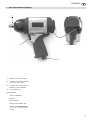
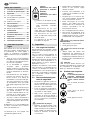
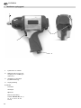
DEUTSCH
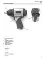
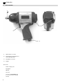
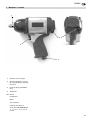
1. Das Gerät im Überblick
1
2
4
3
1 Vierkantaufnahme für Steck-
nüsse
2 Umschalthebel für Rechts-/
L
inkslauf und für Einstellung
des Drehmomentes
3 Aufnahme für Stecknippel
(Druckluft-Anschluss)
4 Abzughebel
Ohne Abbildung:
Kunststoffkoffer
Stecknippel
Ölfläschchen
Leitungsöler
Stecknüsse für SR 1500 Set
(10
, 11, 13, 14, 17, 19, 21, 22,
24, 27 mm)
XK0034D3.fm Originalbetriebsanleitung DEUTSCH

4
DEUTSCH
1. Das Gerät im Überblick................3
2. Zuerst lesen!.................................4
3. Sicherheit......................................4
3.1 Bestimmungsgemäße
Verwendung ...................................4
3.2 Allgemeine Sicherheitshinweise.....4
3.3 Symbole auf dem Gerät .................4
4. Betrieb...........................................4
4.1 Vor dem ersten Betrieb ..................4
4.2 Werkzeug benutzen .......................5
5. Wartung und Pflege .....................5
6. Lieferbares Zubehör.....................5
7. Reparatur ......................................5
8. Umweltschutz ...............................5
9. Technische Daten.........................5
Diese Betriebsanleitung wurde so
erstell
t, dass Sie schnell und sicher mit
Ihrem Werkzeug arbeiten können. Hier
ein kleiner Wegweiser, wie Sie diese
Betriebsanleitung lesen sollten:
Lesen Sie diese Betriebsanleitung
vor der Inbetriebnahme ganz durch.
Beachten Sie insbesondere die
Sicherheitshinweise.
Wen
n Sie beim Auspacken einen
Transportschaden feststellen,
benachrichtigen Sie umgehend
Ihren Händler. Nehmen Sie das
Werkzeug nicht in Betrieb!
Diese Betriebsanleitung richtet sich
an Personen mit technischen
Grundkenntnissen im Umgang mit
Werkzeugen wie dem hier beschrie-
benen. Wenn Sie keinerlei Erfah-
rung mit solchen Werkzeugen
hab
en, sollten Sie zunächst die Hilfe
von erfahrenen Personen in
Anspruch nehmen.
Bewahren Sie alle mit diesem Werk-
zeug gelieferten Unterlagen auf,
damit Sie
sich bei Bedarf informie-
ren können. Bewahren Sie den
Kaufbel
eg für eventuelle Garantie-
fälle auf.
Wen
n Sie das Werkzeug einmal
verleihen oder verkaufen, geben Sie
alle mitgelieferten Unterlagen mit.
Für Schäden, die entstehen, weil diese
Betrieb
sanleitung nicht beachtet wurde,
übernimmt der Hersteller keine Haftung.
Die Informationen in dieser Betriebsan-
leitung sind wie folgt gekennzeichnet:
Gefahr!
Warnung vor Personen-
schäden oder Umwelt-
schäden.
Achtung!
Warnung vor Sach-
schäden.
Zah
len in Abbildungen (1, 2, 3, ...)
kennze
ichnen Einzelteile;
sind fortlau
fend durchnumme-
riert.
Hand
lungsanweisungen, bei denen
die Reihenfolge beachtet werden
muss, sind durchnummeriert.
Handlungsanweisungen mit belie-
biger Reihenfolge sind mit einem
Punkt g
ekennzeichnet.
Auflistunge
n sind mit einem Strich
gekennzeichnet.
3.1 Bestimmungsgemäße
Verwendung
Dieses Werkzeug dient zum Befestigen
und Lösen von Sechskantschrauben
und Sechskantmuttern.
Dieses Werkzeug darf nur durch einen
Druckluftkompressor angetrieben wer-
den. Der in den Technischen Daten
angegebene maximal zulässige Arbeits-
druck darf nicht überschritten werden.
Di
eses Werkzeug darf nicht mit explo-
siven, brennbaren oder gesundheitsge-
fährdenden Gasen betrieben werden.
Jede andere Verwendung ist bestim-
mungswidrig. Durch bestimmungswid-
rige Verwendung, Veränderungen am
W
erkzeug oder durch den Gebrauch von
Teilen, die nicht vom Hersteller geprüft
und freigegeben sind, können unvorher-
sehbare Schäden entstehen!
3.2 Allgemeine Sicherheits-
hinweise
Beachten Sie beim Gebrauch
dieses Werkzeugs die folgenden
Sicherheitshinweise, um Gefahren
für Personen oder Sachschäden
auszuschließen.
Beachten
Sie die speziellen Sicher-
heitshinweise in den jeweiligen
Kapitel
n.
Beachten
Sie gegebenenfalls spezi-
elle Arbeitsschutz- oder Unfallverhü-
tungs-Vorschriften für den Umgang
mi
t Kompressoren und Druckluft-
Werkzeugen.
A
Allgemeine Gefahren!
Halten
Sie Ihren Arbeitsbereich in
Ordnung – Unordnung im Arbeitsbe-
reich kann Unfälle zur Folge haben.
Seien Sie aufmerksam. Benutzen
Sie dieses Werkzeug nicht, wenn
Sie unkonzentriert sind.
Vermeide
n Sie ein Verkanten des
Werkzeugs – sorgen Sie für einen
sicheren Stand, wenn Sie das Werk-
zeug benutzen.
Schließen Sie dieses Werkzeug nur
über eine Schnellkupplung an einen
Kompressor an.
Stellen Sie sicher, dass der in den
Technischen Daten angegebene
maximal zulässige Arbeitsdruck
nicht überschritten wird.
Überlasten Sie dieses Werkzeug
nicht – benutzen Sie dieses Werk-
zeug nur im Leistungsbereich, der in
den
Technischen Daten angegeben
ist.
Berühren Sie keine rotierenden
Teile.
Trennen Sie dieses Werkzeug vom
Druckluftanschluss, bevor Sie
Stecknüsse wechseln oder wenn
das Werkzeug unbeaufsichtigt ist.
A
Gefahr durch unzureichende
persönliche Schutzausrüstung!
Trag
en Sie einen Gehörschutz.
Tragen Sie eine Schutzbrille.
A
Gefahr durch Mängel am
Gerät!
Reparieren Sie dieses Werkzeug
nicht selbst! Nur Fachleute dürfen
Reparaturen an Kompressoren,
Druckbehältern und Druckluft-Werk-
zeugen durchführen.
A
Achtung:
Schützen Sie das Gerät, insbe-
sondere den Druckluftanschluss, die
Vie
rkantaufnahme und die Bedien-
elemente vor Staub und Schmutz.
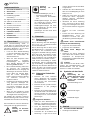
3.3 Symbole auf dem Gerät
Gefahr!
Missachtung der fol-
genden Warnungen kann
zu sch
weren Verlet-
zungen oder Sachschä-
den führen.
Betriebsanleitung lesen.
Gehörschutz tragen.
Schutzbrille tragen.
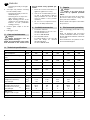
4.1 Vor dem ersten Betrieb
Stecknippel einschrauben.
Inhaltsverzeichnis
2. Zuerst lesen!
3. Sicherheit
4. Betrieb

5
DEUTSCH
4.2 Werkzeug benutzen
A
Achtung:
Damit dieses Werkzeug lange
eins
atzbereit bleibt, muss es ausrei-
chend mit Pneumatiköl versorgt wer-
den. Dies kann wie folgt geschehen:
Über eine Wartungseinheit mit
Öler am Kompressor.
Über einen Anbauöler, der in die
Druckluftleitung oder direkt am
Druckluftwerkzeug installiert ist.
Pro 15 Betriebsminuten (Dauer-
einsatz) etwa 3 bis 5 Tropfen
Pneumatiköl von Hand in den
Druckluftanschluss geben.
1. Stecknuss auf die Vierkantauf-
nahme stecken.
2. Drehrichtung am Umschalthebel für
R
echts-/Linkslauf einstellen:
U
mschalthebel nach links:
Rechtslauf
Umschalthebel ganz nach rechts:
Linkslauf
3. Das Drehmoment (nur bei Rechts-
lauf) am Umschalthebel einstellen:
U
mschalthebel ganz nach links =
Maximales Drehmoment.
U
mschalthebel eine Stufe nach
rechts = Drehmoment wird klei-
ner.
Arbeitsdruck am Kompressor ein-
stellen (maximal zulässiger
Arbeitsdruck siehe Technische
Daten).
4. Schnellkupplung an die Druckluft-
versorgung anschließen.
5. Zum Einschalten, Abzughebel betä-
tigen.
A
Gefahr!
Vor allen Arbeiten am Werk-
zeug Druckluftanschluss trennen.
Weitergehende Wartungs- oder Repa-
raturarbeiten, als die in diesem Kapi-
tel beschriebenen, dürfen nur Fach-
kräfte durchführen.
Ve
rschraubungen auf festen Sitz
prüfen, ggf. festziehen.
Wenn das Werkzeug nicht durch
eine Wartungseinheit oder einen
Anbauöler geölt wird, pro 15
Betriebsminuten (Dauereinsatz)
etwa 3 bis 5 Tropfen Pneumatiköl
von Hand in den Druckluftan-
schluss geben.
Werkzeug nicht ungeschützt im
Freien oder in feuchter Umgebung
aufbewahren.
Pneumatiköl 0,5 Liter
Spezialöl für Druckluftwerkzeuge,
W
artungseinheiten und Anbauöler.
Art.-Nr. 090 100 8540
An
bauöler R3/8" Innengewinde
Zur Installation direkt an Druckluft-
werkzeugen. Stets sichtbarer
Ölstand
durch Schauglas.
Art.-Nr. 090 105 4592
A
Gefahr!
Reparaturen an Druckluftwerk-
zeugen dürfen nur durch eine Fach-
kraft ausgeführt werden!
Reparaturbedürftige Druckluftwerkzeuge
können an die Service-Niederlassung
Ihres Landes eingesandt werden. Die
Adresse finden Sie bei der Ersatzteil-
liste.
Bitte beschreiben Sie bei der Einsen-
dung zur Reparatur den festgestellten
Fe
hler.
Das Verpackungsmaterial der Maschine
ist zu 100 % recyclingfähig.
Ausgediente Maschinen und Zubehör
enthalten große Mengen wertvoller Roh-
und Kunststoffe, die ebenfalls einem
Recyclingprozess zugeführt werden
können.
Die Anleitung wurde auf chlorfrei
ge
bleichtem Papier gedruckt.
5. Wartung und Pflege
6. Lieferbares Zubehör
7. Reparatur
8. Umweltschutz
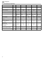
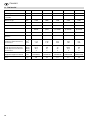
9. Technische Daten
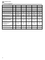
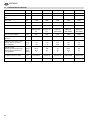
Modell SR 1500 Set SR 2700 SR 2900 SR 3500 SR 4500
Luftbedarf l/min 360 400 400 600 600
Maximal zulässiger Arbeitsdruck bar 6,3 6,2 6,2 6,3 6,3
Drehzahl min
-1
7500 7000 7500 5500 5500
Vierkantaufnahme " 1/2 1/2 1/2 3/4 1
Maximale Schraubengröße M16 M16 M16 M32 M32
Schlagwerk Hammer-
schlagwerk
Stiftschlag-
werk
Doppelhammer-
Sch
lagwerk
Doppelhammer-
Schlagwerk
Doppelhammer-
Schlagwerk
Maximales Drehmoment Nm 360 610 670 1490 1490
Minimaler Schlauchdurch-
messer (innen)
mm 10 10 10 13 13
Vibration (gewichteter Effektiv-
wert der Beschleunigung)
Unsicherheit K
m/s
2
m/s
2
< 2,5
1,23
2,89
1,45
4,52
2,26
3,24
1,62
6,71
2,68
EN ISO 15744
Schallleistungspegel L
WA
Schalldruckpegel L
PA
Unsicherheit K
dB (A)
dB (A)
dB (A)
107,8
96,8
4
108
97
4
99
88
4
108,9
97,9
4
102
91
4
Abmessungen:
Länge x Breite x Höhe mm 195x70x195 195x70x195 195x70x195 230x97x240 230x97x240
Gewicht kg 2,0 2,5 2,5 5,7 5,8

6
ENGLISH
1. Tool overview
1
2
4
3
1 Square drive for sockets
2 Reversing lever forward/reverse
and torque
adjustment
3 Plug nipple on air inlet
4 Trigger
Not shown:
Plastic carrying case
Plug nipple
Oil flask
Line oiler
Sockets for SR
1500 Set (10,
11, 13, 14, 17, 19, 21, 22, 24,
27 mm)
XK0034E3.fm Original operating instructions ENGLISH

7
ENGLISH
1. Tool overview..............................6
2. Please read first!.........................
7
3. Safety...........................................7
3.1 Specified conditions of use ...........7
3.2 General safety instructions ...........7
3.3 Symbols on the tool ......................7
4. Operation.....................................7
4.1 Before initial operation..................7
4.2 Using the tool................................7
5. Care and maintenance ...............8
6. Available accessories ................8
7. Repairs.........................................8
8. Environmental protection ..........8
9. Technical specifications ............8
These instructions are written in a way to
let you
work with the tool quickly and
safely. Here is how to use the instruc-
tions:
R
ead these instructions fully before
operating the tool. Pay special
attention to the safety information.
If you notice transport damage while
unpacking, notify your supplier
immediately. Do not operate the
tool!
These instructions are intended for
individuals having a basic technical
knowledge in the handling of tools
like the one described herein. If you
have no experience whatsoever with
such tool, we strongly recommend
to seek the advise of experienced
individuals.
Ke
ep all documents supplied with
this tool for future reference. Also,
retain proof of purchase in case of a
warranty claim.
Sh
ould you rent or sell the tool, pass
on all documents supplied with the
tool.
The manufacturer is not liable for any
da
mage arising from neglect of these
operating instructions.
Information in these instructions is
de
noted as under:
Danger!
Risk of personal injury or
e
nvironmental damage.
Caution!
Risk of material damage.
N
umbers in illustrations (1, 2, 3, ...)
d
enote component parts;
a
re consecutively numbered;
Instructions to b
e carried out in a
certain sequence are numbered.
Instructions which can be carried
out in any sequence are indicated
by a bullet (•).
Listings are indicated by an En Dash
(–).
3.1 Specified conditions of
use
This tool is used for running, driving and
removing nuts and bolts.
This tool shall only be powered by an air
compressor. The max. permissible work-
ing pressure stated in the Technical
specifications must not be exceeded.
This tool must not be operated with
gases that are explosive, combustible or
detrimental to health.
Any other use is not as specified. Use
no
t as specified, modification of the tool
or use of parts that are not approved by
the equipment manufacturer, can cause
unforeseeable damage!
3.2 General safety instruc-
tions
When using this air tool follow the
safety instructions given below, to
exclude the risk of personal injury or
material damage.
Please also observe the special
safety instructions in the respective
chapters.
Observe the statuary accident insur-
ance institution regulations and reg-
ulations for the prevention of acci-
dents pertaining to the operation of
a
ir compressors and air tools, where
applicable.
A
General hazards!
Ke
ep your work area tidy – a messy
work area invites accidents.
Be
alert. Do not operate this tool
while under the influence of drugs,
alcohol or medication.
Keep the tool from jamming –
ensure firm footing when using the
tool.
Always use a quick coupler to con-
nect this air tool to a compressor.
Make
sure that the max. permissible
working pressure stated in the Tech-
nical specifications is not exceeded.
Do not overload tool – use it only
within the performance range it was
designed for (see Technical specifi-
cations).
Do
not touch any rotating parts.
D
isconnect tool from air supply
before changing sockets or if left
unattended.
A
Hazard generated by insuffi-
cient personal protection gear!
Wear hearing protection.
Wear safety
glasses.
A
Hazard generated by tool
defects!
Do not
attempt to repair the tool
yourself! Only trained specialists are
permitted to service or repair com-
pressors, pressure vessels and air
tools.
A
Caution:
Protect the tool, air inlet, drive
square, and operating elements in par-
ticular, from dust and dirt.
3.3 Symbols on the tool
Danger!
Neglect of the following
warnin
gs may cause
severe injury or material
damage.
Read instructions.
Wear hearing protection.
Wear safety goggles.
4.1 Before initial operation
Screw the plug nipple in.
4.2 Using the tool
A
Caution:
To ensure a long service life of
this tool, it needs to be supplied with
sufficient quantities of pneumatic oil.
This can be achieved by:
a service unit with oiler at the
compressor.
a lubricator, installed in the air
line or directly on the air tool.
ad
ding approx. 3-5 drops of pneu-
matic oil by hand every 15 minuts
of use
(constant operation) to the
air inlet.
1. Put socket on the drive.
2. Set direction of rotation with the
rev
ersing lever:
Reversing lever to the left:
forward
Table of Contents
2. Please read first!
3. Safety
4. Operation

8
ENGLISH
Reversing lever fully to the right:
reverse
3. Set torque only with the reversing
lever in forward position:
Reversin
g lever fully to the left =
maximum torque.
Reversing lever one step to the
right = torque is reduced.
Adjust worki
ng pressure at the
compressor (see Technical spec-
ifications for max. permissible
working pressure).
4. Connect quick coupler to the air
supply.
5. Pull trigger to start.
A
Danger!
Always disconnect from air
supply before servicing.
Repair and maintenance work other
th
an described in this section must
only be carried out by qualified spe-
cialists.
Check al
l screwed connections for
tightness, tighten if necessary.
If the tool is not lubricated by a serv-
ice unit or line lubricator, add 3-5
drops pneumatic oil to the air inlet
every 15 minutes of use (constant
operation).
Do not store tool unprotected out-
doors or in damp environment.
Pneuma
tic oil 0.5 litre
Special lubricant for air tools, serv-
ice units and line oilers.
Stock-no. 090 100 8540
Line oiler R3/8" female
For fitting directly to air tools. Oil
level can always be checked
through sight glass.
Stock-no. 090 105 4592
A
Danger!
Repairs to air tools must be
carried out by qualified specialist
ONLY!
Air tools in need of repair can be send to
the service centre in your country. See
spare parts list for address.
Please attach a description of the fault to
the power tool.
The tool's packaging can be 100 % recy-
cled.
Worn out machines and accessories
contain considerable amounts of valua-
ble raw and plastic materials, which can
be
recycled.
These instructions are printed on chlo-
rine-free bleached paper.
5. Care and maintenance
6. Available accessories
7. Repairs
8. Environmental protection
9. Technical specifications
Model SR 1500 Set SR 2700 SR 2900 SR 3500 SR 4500
Air consumption l/min 360 400 400 600 600
Max. permissible working pres-
sure
bar 6.3 6.2 6.2 6.3 6.3
Speed min
-1
7500 7000 7500 5500 5500
Square drive " 1/2 1/2 1/2 3/4 1
Maximum bolt size M16 M16 M16 M32 M32
Impact mechanism rotary
hammer
jumbo ham-
mer
twin hammer twin hammer twin hammer
Maximum torque Nm 360 610 670 1490 1490
Minimum hose size (inner) Nm 10 10 10 13 13
Vibration (effective value of
we
ighted acceleration)
Uncertainty K
m/s
2
m/s
2
< 2.5
1.23
2.89
1.45
4.52
2.26
3.24
1.62
6.71
2.68
EN ISO 15744
Sound power level L
WA
Sound pressure level L
PA
Uncertainty K
dB (A)
dB (A)
dB (A)
107.8
96.8
4
108
97
4
99
88
4
108.9
97.9
4
102
91
4
Dimensions:
length x width x height mm 195x70x195 195x70x195 195x70x195 230x97x240 230x97x240
Weight kg 2.0 2.5 2.5 5.7 5.8

9
FRANÇAIS
1. Vue d'ensemble de l'appareil
1
2
4
3
1 Fixation carrée pour douilles
2 Levier pour la sélection du sens
d
e rotation et du couple
3 Logement pour embout (raccor-
dement pour air comprimé)
4 Levier d'extraction
Sans illustration :
Coffret en plastique
Embouts
Burette d'huile
Graisseur de conduite d'air
Douilles pour se
t SR 1500 (10,
11, 13, 14, 17, 19, 21, 22, 24,
27 mm)
XK0034F3.fm Instructions d’utilisation originales FRANÇAIS

10
FRANÇAIS
1. Vue d'ensemble de l'appareil .....9
2. A lire en premier !......................10
3. Sécurité......................................10
3.1 Utilisation conforme aux
prescriptions................................10
3.2 Consignes de sécurité
générales ....................................10
3.3 Symboles sur l'appareil ...............10
4. Fonctionnement ........................11
4.1 Avant la première mise
en service....................................11
4.2 Utiliser l'outil ................................11
5. Maintenance et entretien ..........11
6. Accessoires disponibles..........11
7. Réparations ...............................11
8. Protection de
l'environnement.........................11
9. Caractéristiques Techniques ...12
Ces instructions ont été conçues de
façon
à permettre à l'utilisateur de tra-
vailler rapidement et sûrement avec son
outil. Voici quelques indications de lec-
ture de ces instructions :
Lire entièrement ces instructions
avant de mettre en marche la
machine. Respecter en particulier
les instructions de sécurité.
Si des d
ommages dus au transport
sont constatés pendant le déballa-
ge, en informer aussitôt le reven-
deur. Ne pas mettre
l'outil en mar-
che !
Ces i
nstructions d'utilisation s'adres-
sent à des personnes possédant
des con
naissances de base techni-
ques concernant le maniement
d'outils tels q
ue celui décrit ici. Nous
recommandons aux personnes ne
disposant pas de ces bases de se
faire assister par des personnes
plus expérimentées.
Conse
rver toute la documentation
fournie avec l'appareil afin de pou-
voir les consulter ultérieurement en
cas
de besoin. Conserver le justifi-
catif de paiement pour éventuelle-
ment faire appel à la garantie.
En
cas de vente ou de location de
l'appareil, fournir également ces ins-
tructions.
Le fabricant décline toute responsabilité
en cas de dommages dus au non-res-
pect de ces instructions.
Les informations des prés
entes instruc-
tions sont caractérisées comme ceci :
Danger !
Avertissement d'un ris-
que de blessure ou de
po
llution.
Attention !
Avertissement d'un ris-
que de dommage maté-
riel.
Les
chiffres sur les illustrations (1, 2,
3...)
caractérisent les différentes piè-
ces ;
se
suivent en ordre croissant.
Les man
ipulations à effectuer dans
un ordre précis sont numérotées.
Les manipulations à effectuer sans
ordre précis sont précédées d'un
point.
Les listes sont caractérisées par des
traits.
3.1 Utilisation conforme aux
prescriptions
Cet appareil sert à fixer et à desserrer
des vis et des écrous à six pans.
Cet appareil ne doit être entraîné que
par un compresseur à air comprimé. La
pression de travail maximale admissible
indiquée dans les caractéristiques tech-
niques ne doit pas être dépassée. Il ne
faut p
as faire fonctionner cet appareil
avec des gaz explosibles, combustibles
ou présentant un danger pour la santé.
Toute autre utilisation est contraire aux
pre
scriptions. Une utilisation non
conforme aux prescriptions, des modifi-
cations apportées à l'appareil ou l'emploi
de
pièces qui n'ont pas été contrôlées ni
approuvées par le fabricant peuvent
entraîner des dommages imprévisibles !
3.2 Consignes de sécurité
générales
Il faut, lorsque l'on utilise cet outil,
tenir compte des remarques suivan-
tes concernant la sécurité afin
d'exclure d
es dangers pour les per-
sonnes ou des dommages maté-
riels.
Respec
ter les consignes de sécurité
particulières des différents chapi-
tres.
Il faut tenir compte le cas échéant
des prescriptions relatives à la sécu-
rité du travail ou à la prévention des
accide
nts pour le maniement des
compresseurs et des outils à air
comprimé.
A
Principaux dangers !
Ma
intenir le lieu de travail en ordre –
un désordre sur le lieu de travail
peut entraîner des accidents.
Il convient de rester vigilant. Ne pas
utiliser cet outil en cas de manque
de concentration.
Eviter de coincer l'outil – assurer
une bonne stabilité pour utiliser
l'appareil.
Il ne faut raccorder cet outil à un
compresseur que par un raccord
rapide.
S'assurer que la pression de travail
maximale admissible indiquée dans
les caractéristiques techniques n'est
pas dépassée.
Ne pa
s surcharger cet outil – Il ne
faut utiliser cet outil que dans la
plage de puissance indiquée dans
les caractéristiques techniques.
Ne pa
s toucher de pièce en rotation.
Il faut déconnecter cet outil de l'ali-
mentation en air comprimé avant de
changer des douilles ou quand l'outil
n'est pas surveillé.
A
Danger dû à un équipement de
protection personnel insuffisant !
Porter une protection acoustique.
Porte
r des lunettes de protection.
A
Danger dû à une défaillance de
l'outil !
N
e pas réparer l'outil soi-même ! Les
travaux de réparation sur les compres-
seurs, sur les ballons et les appareils
p
neumatiques ne doivent être exécu-
tés que par des professionnels.
A
Attention :
Protéger l'appareil, en particulier
l'alimentation en air comprimé, le man-
drin quatre pans et les éléments de com-
mande de la poussière et des saletés.
3.3 Symboles sur l'appareil
Danger !
Le non-respect des avertis
-
sements suivants peut ame-
ner à des blessures ou des
dég
âts matériels graves.
Lire les instructions d'utili-
sation.
Porter une protection
acoustique.
Porter des lunettes de pro-
tection.
Table des matières
2. A lire en premier !
3. Sécurité

11
FRANÇAIS
4.1 Avant la première mise
en service
Visser l'embout.
4.2 Utiliser l'outil
A
Attention :
Afin que la machine soit tou-
jours prête à être utilisée, il faudra la
lu
brifier souvent d'huile pneumati-
que. Ce pr
ocessus peut être réalisé
de la manière suivante :
Par un
e unité de maintenance
avec graisseur sur le compres-
seur.
Par un graisseur ajouté qui est
installé dans la conduite à air
comprimé ou directement sur
l'outil à air comprimé.
Il fau
t mettre environ 3 à 5 gout-
tes d'huile pneumatique à la main
da
ns l'alimentation à air compri-
mé pour 15 minutes de service
(utilisation continue).
1. Enficher la douille sur la fixation car-
rée.
2. Régler le sens de rotation sur le
levier de sélection pour la marche à
droite/à gauche :
Levier orienté à gauche :
rotation à droite
Le
vier orienté complètement à
droite :
rotation à gauche
3. Réglage du couple au niveau du
levier (uniquement en rotation à
droite) :
L
evier complètement à gauche =
couple maximal.
L
evier d'un cran à droite = couple
plus faible.
Ré
gler la pression de travail sur
le compresseur (consulter les
caractéristiques techniques pour
la pression de travail maximale
admise).
4. Raccorder l'accouplement rapide
su
r l'alimentation en air comprimé.
5. Actionner le levier d'extraction pour
l
'enclenchement.
A
Danger !
Avant de commencer le travail
av
ec cet outil, débrancher la
connexion de l'air comprimé.
Les travaux de maintenance et de
r
éparation autres que ceux décrits
dans ce chapitre ne doivent être exé-
cutés que par un personnel compé-
tent.
Contrôler les assemblages par vis
et les resserrer à fond en cas de
besoin.
Si l'outil n'est pas lubrifié au moyen
d'une unité d'entretien ou d'un lubri-
ficateur, introduire manuellement
tout
es les 15 minutes de fonctionne-
ment (en fonctionnement continu)
e
ntre 3 et 5 gouttes d'huile pneuma-
tique dans l'alimentation en air com-
primé.
Ne pas conserver l'outil sans protec-
tion en plein air ou dans un environ-
nement humide.
H
uile pneumatique de 0,5 litre
Huile spéciale pour outils pneumati-
ques, pour unités d'entretien et lubri-
ficateurs.
Numéro d'article : 090 100 8540
L
ubrificateur de filet intérieur R3/8"
A installer directement dans les
outils pneumatiques. Le niveau
d'huile sera toujours visible à travers
le regard.
Numéro d'article : 090 105 4592
A
Danger !
Les travaux de réparation des
outils pneumatiques do
ivent être réa-
lisés exclusivement par des électri-
ciens spécialisés!
Les outils qui nécessitent une réparation
peuvent être envoyés à la succursale du
service clients de votre pays dont
l'adresse figure avec la liste des pièces
de rechange.
Prière de joindre une description du
dé
faut constaté à l'outil expédié.
Le matériau d'emballage de la machine
e
st recyclable à 100 %.
Les machines et accessoires électriques
qui ne sont plus utilisés contiennent de
grandes quantités de matières premiè-
res et de matières plastiques de grande
qu
alité pouvant être également recy-
clées.
Les présentes instructions ont été impri-
mées sur papier blanchi sans chlore.
4. Fonctionnement
5. Maintenance et entretien
6. Accessoires disponibles
7. Réparations
8. Protection de l'environ-
nement

12
FRANÇAIS
9. Caractéristiques Techniques
Modèle Set SR 1500 SR 2700 SR 2900 SR 3500 SR 4500
Besoins en air l/min 360 400 400 600 600
Pression d'air maximale admissi-
ble
bar 6,3 6,2 6,2 6,3 6,3
Vitesse de rotation tr/min 7500 7000 7500 5500 5500
Fixation carrée " 1/2 1/2 1/2 3/4 1
Taille de vis maximale M16 M16 M16 M32 M32
Mécanisme de frappe Système de
frappe à mar-
teau
Système pin
clus
h
Système de
frappe à double
marteau
Système de
frappe à double
marteau
Système de
frappe à dou-
ble marteau
Couple maximal Nm 360 610 670 1490 1490
Diamètre (intérieur) minimal de
flexible
mm 10 10 10 13 13
Vibration (valeur efficace pondé-
rée de l’accélération)
Incertitude K
m/s
2
m/s
2
< 2,5
1,23
2,89
1,45
4,52
2,26
3,24
1,62
6,71
2,68
EN ISO 15744
Niveau de puissance acoustique L
WA
Niveau sonore L
PA
Incertitude K
dB (A)
dB (A)
dB (A)
107,8
96,8
4
108
97
4
99
88
4
108,9
97,9
4
102
91
4
Dimensions :
longueur x largeur x hauteur mm 195x70x195 195x70x195 195x70x195 230x97x240 230x97x240
Poids kg 2,0 2,5 2,5 5,7 5,8

13
NEDERLANDS
1. Het apparaat in een oogopslag
1
2
4
3
1 Vierkant opnamestuk voor dop-
sleutels
2 Omschakelhendel voor rechts-/
l
inksloop en voor de instelling
van het draaimoment
3 Opname voor steeknippel (per-
slucht-aansluiting)
4 Trekker
Geen tekening:
Kunststofkoffer
Steeknippel
Olieflesje
Doorsmeerapparaat
Steekkoppen voor SR 1500
set
(10, 11, 13, 14, 17, 19, 21, 22,
24, 27 mm)
XK0034H3.fm Origineel gebruikaanwijzing NEDERLANDS

14
NEDERLANDS
1. Het apparaat in een
oogopslag.................................13
2. Lees dit eerst!...........................14
3. Veiligheid..................................14
3.1 Voorgeschreven gebruik
van het systeem.........................
14
3.2 Algemene
veiligheidsinstructies..................14
3.3 Symbolen op het toestel ............14
4. Bediening..................................15
4.1 Vóór het eerste bedrijf.............15
4.2 Gereedschap gebruiken.............15
5. Service en onderhoud .............15
6. Beschikbare accessoires ........15
7. Reparatie...................................15
8. Milieubescherming ..................15
9. Technische gegevens..............16
Deze gebruiksaanwijzing werd zo ver-
vaardigd, dat u snel en veilig met uw
ge
reedschap kunt werken. Hier een
kleine wegwijzer, hoe u deze gebruiks-
aanwijzing dient te lezen:
Lees deze gebruiksaanwijzing vóór
de ingebruikneming geheel door.
Besteed daarbij vooral aandacht
aan het hoofdstuk „veiligheidsvoor-
schriften”.
Als u bij
het uitpakken van het appa-
raat transportschade vaststelt, dan
moet u daar onmiddellijk uw leve-
rancier van op de hoogte stellen.
Neem h
et gereedschap niet in
bedrijf!
Deze gebruiksaanwijzing richt zich
aan personen met technische basis-
kennis in de omgang met gereed-
schap zoals het hier beschreven.
In
dien u generlei ervaring met zulk
gereedschap heeft, dient u eerst
beroep te doen op de hulp van erva-
ren personen.
Be
waar alle met dit gereedschap
geleverde documenten op, opdat u
zich desgewenst kunt informeren.
Bewaar het koopbewijs voor moge-
lijke garantiegevallen op.
Als u
het gereedschap verleent of
verkoopt, geef dan alle meegele-
verde documenten mee.
Voor schade die ontstaat, omdat deze
gebruiksaanwijzing niet werd opgevolgd,
overneemt de fabrikant geen aansprake-
lijkheid.
De informaties in deze gebruiksaanwij-
zing zijn op de volgende manier geken-
merkt:
Gevaar!
Waarschuwing voor
l
ichamelijk letsel of
milieuschade.
Attentie!
Waarschuwing voor
materiële schade.
Ge
tallen in afbeeldingen (1, 2, 3, ...)
kenmerken
afzonderlijke delen;
zijn do
orlopend genummerd.
Hand
elingsinstructies, waarbij op de
volgorde dient te worden gelet, zijn
doorgenummerd.
Handelingsinstructies met willekeu-
rige volgorde zijn met een punt
geken
merkt.
Op
sommingen zijn met een streep
gekenmerkt.
3.1 Voorgeschreven gebruik
van het systeem
Dit gereedschap dient ter bevestiging en
voor het losmaken van zeskantschroe-
ven en zeskantmoeren.
Dit gereedschap mag uitsluitend door
een persluchtcompressor worden aan-
gedreven. De maximaal toegelaten
we
rkdruk vermeld in de technische
gegevens mag niet worden overschre-
den. Dit gereedschap mag niet met
exp
losieve, brandbare of gezondheids-
bedreigende gassen worden geëxploi-
teerd.
Elk ander gebruik is verboden. Door
on
reglementair gebruik, veranderingen
aan het gereedschap of door gebruik
van onderdelen, die niet door de fabri-
kant werden gekeurd en vrijgegeven,
kan
onvoorziene schade ontstaan!
3.2 Algemene veiligheidsin-
structies
Houdt u zich bij gebruik van dit
gereedschap aan de volgende vei-
ligheidsvoorschriften om gevaar
voor p
ersonen of materiële schade
te voorkomen.
Houd rekening met de bijzondere
veiligheidsinstructies in de desbe-
treffende hoofdstukken.
Houdt u zich eventueel aan de bij-
zondere wettelijke maatregelen ter
bescherming van de werknemer of
de ongevallenpreventievoorschriften
inzake de omgang met compresso-
ren en persluchtgereedschap.
A
Algemene gevaren!
H
oud uw werkplek in orde – een
wanordelijke werkplek kan ongeval-
len tot gevolg hebben.
Wees aandachtig. Gebruik dit
gereedschap niet, wanneer u niet
geconcentreerd bent.
Vermijd een kantelen van het
gereedschap - zorg voor een veilige
stand als u het gereedschap benut.
Sluit dit gereedschap uitsluitend via
een snelkoppeling aan op een com-
pressor.
Vergewis u ervan dat de maximaal
toegelaten werkdruk vermeld in de
technische gegevens niet over-
schreden wordt.
Zorg
dat u dit gereedschap niet
overbelast – gebruik dit gereed-
schap uitsluitend binnen het vermo-
gensbereik dat in de technische
geg
evens vermeld wordt.
Raak g
een roterende onderdelen
aan.
Koppel het gereedschap los van de
persluchtaansluiting, alvorens u
dopsleutels vervangt of wanneer u
het gereedschap onbewaakt laat.
A
Gevaar door ontoereikende
persoonlijke veiligheidsuitrusting!
Draag oordoppen.
Draag
een veiligheidsbril.
A
Gevaar door gebreken aan het
toestel!
Voer nooit zelf reparaties aan het
gereedschap uit! Reparaties van
compressoren, drukvaten en per-
sluchtgereedschap mogen uitslui-
tend door gekwalificeerd personeel
uitgevo
erd worden.
A
Attentie:
Bescherm het toestel, vooral de
persluchtaansluiting, de vierkante
opname en de bedieningselementen
tegen stof en vuil.
3.3 Symbolen op het toestel
Gevaar!
Veronachtzaming van de
volg
ende waarschuwin-
gen kan tot zware ver-
wondingen of materiële
sch
ade leiden.
Gebruiksaanwijzing lezen.
Oordoppen dragen.
Veiligheidsbril dragen.
Inhoudstafel
2. Lees dit eerst!
3. Veiligheid

15
NEDERLANDS
4.1 Vóór het eerste bedrijf
Steeknippel inschroeven.
4.2 Gereedschap gebruiken
A
Attentie:
Opdat dit gereedschap lange
tijd
klaar voor gebruik blijft, moet het
voldoende met pneumatische olie
worden verzorgd. Dit kan als volgt
gebeuren:
Via een onderhoudseenheid met
doorsmeerapparaat aan de com-
pressor.
Via een opbouwsmeerpot die in
de persluchtleiding of onmiddel-
lijk aan het persluchtgereedschap
ge
ïnstalleerd is.
D
oe per 15 bedrijfsminuten (lang-
durig gebruik) ca. 3 tot 5 druppels
pn
eumatische olie met de hand in
de persluchtaansluiting.
1. Steek de dopsleutel op het vierkante
opnamestuk.
2. Draairichting aan de omschakelhen-
del voor rechts-/linksloop instellen:
Omschakel
hendel naar links:
rechtsloop
Omschakelhendel geheel naar
rechts:
linksloop
3. Het draaimoment (alleen bij
rechtsloop) aan de omschakelhen-
del instellen:
o
mschakelhendel geheel naar
links = maximaal draaimoment.
omschakelhendel een trap naar
rechts = draaimoment wordt klei-
ner.
Stel
de werkdruk op de compres-
sor in (maximaal toegelaten
w
erkdruk zie Technische gege-
vens).
4. Snelkoppeling aan de persluchtver-
zorging aansluiten.
5. Beweeg de trekker om in te schake-
len.
A
Gevaar!
Koppel de persluchtaanslui-
ting los vóór alle werkzaamheden aan
het gereedschap.
Service en/of onderhoudswerkzaam-
heden die niet in dit hoofdstuk
be
schreven staan mogen uitsluitend
door vaklui uitgevoerd worden.
Controleer of de schroefverbindin-
gen vast zitten, en draai ze vast
i
ndien nodig.
W
anneer het gereedschap niet door
een onderhoudsmodule of een aan-
bouwsmeerpot wordt geolied, doe
d
an elke 15 bedrijfsminuten (langdu-
rig gebruik) ca. 3 tot 5 druppels
pneumatische olie met de hand in
de persluchtaansluiting.
Het gereedschap mag niet in de
open lucht of in een vochtige ruimte
opgeborgen worden.
Pneumatische olie 0,5 l
speciale olie voor persluchtgereed-
schap, onderhoudsmodules en aan-
bouwsmeerpotten.
Artikelnr. 090 100 8540
Aa
nbouwsmeerpot R3/8" binnen-
schroefdraad
Voor installatie direct op perslucht-
gereedschap. Steeds zichtbaar olie-
peil dankzij het peilglas.
Artikelnr. 090 105 4592
A
Gevaar!
Reparaties aan persluchtge-
reedschap mogen uitsluitend door
va
kmensen worden uitgevoerd!
De persluchtmachines kunnen voor
repa
ratie verzonden worden naar de
Service-vestiging in uw land. Het adres
vindt u terug bij de lijst met onderdelen.
Geef bij inzending voor reparatie een
omschrijvi
ng van het vastgestelde
defect.
Het verpakkingsmateriaal van de
machine is 100 % recycleerbar.
Afgedankte machines en accessoires
be
vatten grote hoeveelheden waarde-
volle grond- en kunststoffen die even-
eens gerecycleerd kunnen worden.
De gebruiksaanwijzing werd op chloor-
vrij gebleekt papier gedrukt.
4. Bediening
5. Service en onderhoud
6. Beschikbare accessoires
7. Reparatie
8. Milieubescherming

16
NEDERLANDS
9. Technische gegevens
Model SR 1500 Set SR 2700 SR 2900 SR 3500 SR 4500
Luchtbehoefte l/min 360 400 400 600 600
Maximaal toegelaten werkdruk bar 6,3 6,2 6,2 6,3 6,3
Toerental min
-1
7500 7000 7500 5500 5500
Vierkant opnamestuk " 1/2 1/2 1/2 3/4 1
Maximale schroevengrootte M16 M16 M16 M32 M32
Slagwerk Hamer-
slagwerk
Stiftslagwerk Duplexhamer-
sl
agwerk
Duplexhamer-
slagwerk
Duplexhamer-
slagwerk
Maximaal draaimoment Nm 360 610 670 1490 1490
Minimale slangdoorsnede
(binnen)
mm 10 10 10 13 13
Trilling (geschatte effectieve
wa
arde van de versnelling)
Onzekerheid K
m/s
2
m/s
2
< 2,5
1,23
2,89
1,45
4,52
2,26
3,24
1,62
6,71
2,68
EN ISO 15744
Geluidsdrukniveau L
WA
Geluidsdruknivau L
PA
Onzekerheid K
dB (A)
dB (A)
dB (A)
107,8
96,8
4
108
97
4
99
88
4
108,9
97,9
4
102
91
4
Afmetingen:
lengte x breedte x hoogte mm 195x70x195 195x70x195 195x70x195 230x97x240 230x97x240
Gewicht kg 2,0 2,5 2,5 5,7 5,8

17
ITALIANO
1. Visione d'insieme dell'apparecchio
1
2
4
3
1 Sede a sezione quadra per
adattatori ad innesto
2 Levetta di commutazione per la
rotazione a destra/sinistra e per
la regolazione della coppia tor-
cente
3 Sede per raccordo filettato
(attacco di erog
azione dell'aria
compressa)
4 Levetta di estrazione
Particolari non illustrati:
Contenitore di plastica
Raccordo filettato
Oliatori
Oliatore del condotto
Adattatori ad innesto per Set
SR 1500 (1
0, 11, 13, 14, 17, 19,
21, 22, 24, 27 mm)
XK0034I3.fm Manuale d’uso originale ITALIANO

18
ITALIANO
1. Visione d'insieme dell'apparec-
chio.............................................17
2. Istruzioni obbligatorie...............18
3. Sicurezza....................................18
3.1 Utilizzo appropriato .....................18
3.2 Istruzioni generali per
la sicurezza .................................18
3.3 Simboli sull'apparecchio..............18
4. Messa in funzione .....................19
4.1 Prima della messa in funzione ....19
4.2 Utilizzo dell'apparecchio..............19
5. Manutenzione ............................19
6. Accessori disponibili su
richiesta .....................................19
7. Riparazione................................19
8. Rispetto dell'ambiente..............19
9. Dati tecnici .................................20
Queste istruzioni per l'uso sono state
rea
lizzate per consentire un utilizzo
rapido e sicuro dell'apparecchio. Di
seguito vengono fornite brevi indicazioni
sulla modalità di lettura delle istruzioni.
Pri
ma di mettere in funzione l'appa-
recchio, leggere interamente le
istruzioni prestando particolare
attenzione alle indicazioni sulla sicu-
rezza.
Se, al
momento dell’apertura
dell’imballo, si notano danni provo-
cati dal trasporto, mettersi immedia-
tamente in contatto col rivenditore.
Non me
ttere in funzione l'apparec-
chio.
Queste istruzioni per l'uso sono
destinate a persone con cono-
scenze tecniche sugli apparecchi
descritti
. Se non si ha alcun tipo di
esperienza con questo tipo di appa-
recchio, richiedere l'aiuto di esperti.
Ten
ere a portata di mano tutta la
documentazione fornita con l'appa-
recchio per poterla consultare se
necessa
rio. Conservare la prova
d'acquisto per eventuali richieste di
intervento in garanzia.
Se si presta o si ven
de l'apparec-
chio, includere anche la relativa
documentazione.
Per eventuali danni derivanti dalla man-
cata osservanza di queste istruzioni per
l'uso, il produttore declina ogni respon-
sabilità.
Le informazioni contenute in queste
istruzio
ni per l'uso utilizzano i simboli illu-
strati di seguito:
Pericolo!
Avvertenza per possibili
da
nni alle persone e
all'ambiente.
Attenzione
Avvertenza per possibili
danni materiali.
I
numeri nelle figure (1, 2, 3, ...)
indi
cano i singoli pezzi;
usano
una numerazione progres-
siva.
Le istruzioni per l'uso per le quali è
necessario seguire la sequenza
indicata sono numerate in ordine
progressivo.
Le istruzioni per l'uso in cui la
sequenza può essere stabilita a
discrezione dell'operatore sono con-
trassegnate da un punto.
Gli
elenchi sono contrassegnati da
un trattino.
3.1 Utilizzo appropriato
Questo apparecchio serve per fissare e
allentare le viti e i dadi esagonali.
Questo apparecchio deve essere azio-
nato solo tramite un compressore pneu-
matico. La pressione di esercizio mas-
sima consentita indicata al paragrafo
"Dati tecnici" non deve essere superata.
Questo apparecchio non deve essere
utilizzato con gas esplosivi, infiammabili
o nocivi per la salute.
Qualsiasi altro utilizzo non è idoneo. In
caso
di utilizzo improprio, di modifiche
all'apparecchio o di impiego di parti non
controllate e autorizzate dal produttore si
possono verificare danni imprevedibili.
3.2 Istruzioni generali per la
sicurezza
Durante l'uso dell'apparecchio,
osservare le seguenti istruzioni rela-
tive alla sicurezza per evitare even-
tuali pericoli per le persone o danni
ma
teriali.
Osservare
in particolare le istruzioni
relative alla sicurezza contenute
nelle singole sezioni.
Rispettare scrupolosamente le
eventuali norme antinfortunistiche e
di sicurezza specifiche per l'uso di
compressori e utensili ad aria com-
pressa.
A
Pericolo generico
Ten
ere sempre in ordine l'ambiente
di lavoro per evitare il rischio di inci-
denti causati da oggetti fuori posto.
Agire con la massima attenzione.
Evitare di azionare l'apparecchio in
momenti di scarsa concentrazione.
Evi
tare di inclinare l'apparecchio e
lavorare sempre in condizioni di sta-
bilità.
L'apparecchio deve essere colle-
gato ad un compressore esclusiva-
mente mediante un innesto rapido.
Accertarsi che la pressione di eser-
cizio massima consentita indicata al
parag
rafo "Dati tecnici" non venga
superata.
Non sovraccaricare l'apparecchio e
usarlo esclusivamente con la
potenza indicata nella sezione "Dati
tecnici".
Non toccare la parti rotanti.
Sco
llegare l'apparecchio dall'attacco
di erogazione dell'aria compressa
prima di cambiare gli adattatori ad
innesto o di lasciarlo incustodito.
A
Pericolo causato da protezione
personale insufficiente
Mu
nirsi di paraorecchie.
Indossare occhial
i protettivi.
A
Pericolo causato da eventuali
anomalie dell'apparecchio
Si raccomanda di astenersi
dall'effettuare personalmente qual-
siasi riparazione. Solo tecnici spe-
cializzati possono eseguire ripara-
zioni su compressori, serbatoi a
pression
e e apparecchi pneumatici.
A
Attenzione
Proteggere l'apparecchio, in par-
ticolare l'attacco di erogazione dell'aria
compre
ssa, la sede a sezione quadra e
gli elementi principali da polvere e spor-
cizia.
3.3 Simboli sull'apparecchio
Pericolo!
La mancata osservanza
del
le seguenti indica-
zioni può provocare ferite
gravi alle persone o danni
materiali ingenti.
Leggere le istruzioni d'uso.
Indossare i paraorecchie.
Indossare gli occhiali di pro-
tezione.
Sommario
2. Istruzioni obbligatorie
3. Sicurezza

19
ITALIANO
4.1 Prima della messa in fun-
zione
Avvitare il raccordo filettato.
4.2 Utilizzo dell'apparecchio
A
Attenzione
Per prolungare la perfetta effi-
cienza dell'apparecchio, è necessario
lu
brificarlo con una quantità ade-
guata di olio per apparecchi pneuma-
tici. La lubrificazione può essere
effettu
ata nel modo seguente:
tramite un'unità di manutenzione
con oliatore nel compressore
tra
mite un oliatore applicato
installato nel condotto dell'aria
compressa oppure direttamente
sull'apparecchio
og
ni 15 minuti di funzionamento
(continuo) applicare manual-
mente 3-5 gocce di olio per appa-
recchi pneumatici nell'attacco di
e
rogazione dell'aria compressa
1. Inserire l'adattatore ad innesto
nell'apposita sede a sezione quadra
2. Regolare il senso di rotazione nella
le
vetta di commutazione verso
destra o sinistra:
Levetta di commutazione verso
sinistra:
rotazione verso destra
Levetta di commutazione com-
pletamente verso destra:
rotazione verso sinistra.
3. Regolare la coppia torcente (solo
nella rotazione verso destra) nella
levetta di commutazione:
Le
vetta di commutazione com-
pletamente a sinistra = coppia
torcente massima.
Levetta di commutazione spostata
di un livello verso destra = diminu-
zione della coppia torcente.
R
egolare la pressione del com-
pressore. Per la pressione mas-
sima consentita, vedere la
se
zione "Dati tecnici".
4. Collegare l'innesto rapido all'alimen-
tazione dell'aria compressa.
5. Per l'attivazione, azionare la levetta
a
d estrazione.
A
Pericolo!
Prima di qualsiasi attivit
à, scol-
legare l'attacco di erogazione dell'aria
co
mpressa.
Gli interventi di ma
nutenzione o di
riparazione non descritti nel presente
capitolo devono essere effettuati
esclusivamente da personale specia-
lizzato.
Ver
ificare che i raccordi a vite siano
serrati saldamente, provvedendo
eventualmente a stringerli.
Se l'apparecchio non viene lubrifi-
cato tramite un'unità di manuten-
zione o un oliatore, lubrificare
man
ualmente l'attacco di eroga-
zione dell'aria compressa ogni 15
min
uti di funzionamento (uso conti-
nuato) con 3-5 gocce di olio per
apparecchi pneumatici.
L'apparecchio non va lasciato incu-
stodito all'aperto né conservato in
luogo umido.
Olio
per apparecchi pneumatici (0,5
litri)
Olio speciale per apparecchi pneu-
matici, unità di manutenzione e olia-
tori.
Cod. art. 090 100 8540
Olia
tore R3/8" con filettatura interna
Per l'installazione diretta in apparec-
chi pneumatici. Livello dell'olio
co
stantemente visibile dall'apposito
vetrino.
Cod. art. 090 105 4592
A
Gefahr!
Le riparazioni di apparecchi
pneumatici devono essere effettuate
esclusivamente da tecnici specializ-
zati.
Gli apparecchi da riparare possono
essere inviati alcentro di assistenza del
proprio paese. L'indirizzo è indicato
nell'elenco dei pezzi di ricambio.
Quando si spedisce un apparecchio per
la ripa
razione, descrivere l'errore accer-
tato.
Il materiale utilizzato per l'imballaggio
de
ll'apparecchio è riciclabile al 100 %.
Gli apparecchi e gli accessori fuori uso
conten
gono grandi quantità di materie
prime e di altri materiali che possono
essere sottoposti ad un processo di rici-
claggio.
Queste istruzioni sono state stampate su
carta sb
iancata senza cloro.
4. Messa in funzione
5. Manutenzione
6. Accessori disponibili su
richiesta
7. Riparazione
8. Rispetto dell'ambiente

20
ITALIANO
9. Dati tecnici
Modello Set SR 1500 SR 2700 SR 2900 SR 3500 SR 4500
Fabbisogno d'aria l/min 360 400 400 600 600
Pressione di esercizio massima
consentita
bar 6,3 6,2 6,2 6,3 6,3
Numero di giri min
-1
7500 7000 7500 5500 5500
Sede a sezione quadra " 1/2 1/2 1/2 3/4 1
Dimensione massima delle viti M16 M16 M16 M32 M32
Battuta Battuta a
mart
ello
Battuta a
punta
Battuta a dop-
pio martello
Battuta a dop-
pio martello
Battuta a dop-
pio martello
Coppia torcente massima Nm 360 610 670 1490 1490
Diametro tubi flessibili
(i
nterno)
mm 10 10 10 13 13
Vibrazione (valore effettivo
p
onderato dell'accelerazione)
Incertezza K
m/s
2
m/s
2
< 2,5
1,23
2,89
1,45
4,52
2,26
3,24
1,62
6,71
2,68
EN ISO 15744
Livello di potenza acustica L
WA
Livello di pressione acustica L
PA
Incertezza K
dB (A)
dB (A)
dB (A)
107,8
96,8
4
108
97
4
99
88
4
108,9
97,9
4
102
91
4
Dimensioni:
lunghezza x larghezza x altezza mm 195x70x195 195x70x195 195x70x195 230x97x240 230x97x240
Peso kg 2,0 2,5 2,5 5,7 5,8
Sidan laddas...
Sidan laddas...
Sidan laddas...
Sidan laddas...
Sidan laddas...
Sidan laddas...
Sidan laddas...
Sidan laddas...
Sidan laddas...
Sidan laddas...
-
 1
1
-
 2
2
-
 3
3
-
 4
4
-
 5
5
-
 6
6
-
 7
7
-
 8
8
-
 9
9
-
 10
10
-
 11
11
-
 12
12
-
 13
13
-
 14
14
-
 15
15
-
 16
16
-
 17
17
-
 18
18
-
 19
19
-
 20
20
-
 21
21
-
 22
22
-
 23
23
-
 24
24
-
 25
25
-
 26
26
-
 27
27
-
 28
28
-
 29
29
-
 30
30


Metabo SR 1500 Bruksanvisningar
- Kategori
- Tillbehör för kaffebryggning
- Typ
- Bruksanvisningar
på andra språk
- italiano: Metabo SR 1500 Istruzioni per l'uso
- español: Metabo SR 1500 Instrucciones de operación
- Deutsch: Metabo SR 1500 Bedienungsanleitung
- français: Metabo SR 1500 Mode d'emploi
- English: Metabo SR 1500 Operating instructions
- dansk: Metabo SR 1500 Betjeningsvejledning
- Nederlands: Metabo SR 1500 Handleiding
Relaterade papper
-
 Elektra Beckum SR4500 Användarmanual
-
Metabo RS 4000 Bruksanvisningar
-
-
-
-
-
-
-
-


