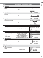
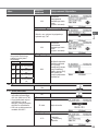
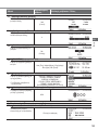
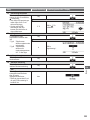
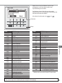
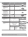
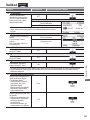
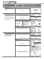
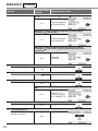
Panasonic WHADC1216H6E5C Bruksanvisningar
- Typ
- Bruksanvisningar

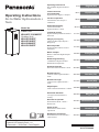
Operating Instructions
Air-to-Water Hydromodule +
Tank
Manufactured by:
Panasonic AVC Networks Czech, s.r.o.
U Panasoniku 1, 320 84 Plzeň , Czech Republic
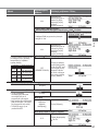
Model No.
Indoor Unit
WH-ADC1216H6E5C
Outdoor Unit
WH-UD12HE5*
WH-UD16HE5*
WH-UX09HE5*
WH-UX12HE5*
Operating Instructions
Air-to-Water Hydromodule +
Tank
2-29
English (EN)
Instrucciones de
funcionamiento
Hydrokit Aire-Agua + Tanque
30-57
Español (ES)
Istruzioni operative
Idromodulo aria-acqua +
serbatoio
58-85
Italiano (IT)
Gebruiksaanwijzing
Lucht-naar-water
Hydromodule + Tank
86-113
Nederlands (NL)
Instrukcja obsługi
Hydromoduł powietrze-woda +
zbiornik
114-141
Polski (PL)
Οδηγίες λειτουργίας
Υδρομονάδα Αέρα-Νερού +
Δεξαμενή
142-169
Ελληνικά (EL)
Návod k použití
Hydromodul vzduch-voda +
zásobník
170-197
Český (CZ)
Mode d’emploi
Ballon + Module Hydraulique
Air/Eau
198-225
Français (FR)
Bedienungsanleitung
Luft/Wasser-Hydromodul +
Warmwasserspeicher
226-253
Deutsch (DE)
Kullanım Kılavuzu
Hava-Su Hidromodülü + Tank
254-281
Türkçe (TR)
Bruksanvisning
Luft-till-vatten hydromodul +
Tank
282-309
Svenska (SV)
Bruksanvisninger
Luft-til-vann Hydromodul +
Tank
310-337
Norsk (NO)
Käyttöohjeet
Ilma-vesikiertomoduuli + säiliö
338-365
Suomi (FI)
Használati útmutató
Levegő-víz hidromodul +
tartály
366-393
Magyar (HU)
Navodila za uporabo
Hidromodul Zrak - Voda +
Rezervoar
394-421
Slovenščina (SL)
Upute za rad
Hidromodul zrak-voda +
spremnik
422-449
Hrvatski (HR)
Naudojimo instrukcijos
Hidromodulis oras-vanduo +
rezervuaras
450-477
Lietuvių (LT)
ACXF55-29440

2
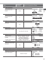
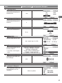
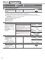
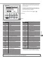
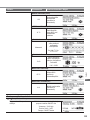
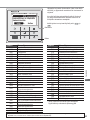
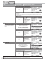
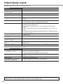
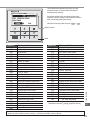
Table of contents
Safety precautions .........................................................4-6
Remote Controller buttons and display .........................7-9
Initialization .......................................................................9
Quick Menu ....................................................................10
Menus ........................................................................10-24
For user
1 Function setup ...................................................10-11
1.1 Weekly timer
1.2 Holiday timer
1.3 Quiet timer
1.4 Room heater
1.5 Tank heater
1.6 Sterilization
1.7 DHW mode
2 System check .........................................................12
2.1 Energy monitor
2.2 System information
2.3 Error history
2.4 Compressor
2.5 Heater
3 Personal setup ...................................................12-13
3.1 Touch sound
3.2 LCD contrast
3.3 Backlight
3.4 Backlight intensity
3.5 Clock format
3.6 Date & Time
3.7 Language
3.8 Unlock password
4 Service contact .......................................................13
4.1 Contact 1 / Contact 2
For installer
5 Installer setup > System setup ..........................14-19
5.1 Optional PCB connectivity
5.2 Zone & Sensor
5.3 Heater capacity
5.4 Anti freezing
5.5 Buffer tank connection
5.6 Base pan heater
5.7 Alternative outdoor sensor
5.8 Bivalent connection
5.9 External SW
5.10 Solar connection
5.11 External error signal
5.12 Demand control
5.13 SG ready
5.14 External compressor SW
5.15 Circulation liquid
5.16 Heat-Cool SW
5.17 Force heater
5.18 Defrost signal
5.19 Pump fl owrate
6 Installer setup > Operation setup ......................19-23
6.1 Heat
6.2 Cool
6.3 Auto
6.4 Tank
7 Installer setup > Service setup ..........................23-24
7.1 Pump maximum speed
7.2 Pump down
7.3 Dry concrete
7.4 Service contact
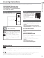
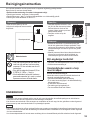
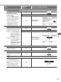
Cleaning instructions ......................................................25
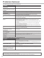
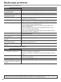
Troubleshooting .........................................................26-27
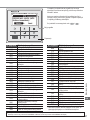
Information .................................................................28-29
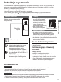
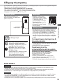
Thank you for purchasing Panasonic product.
Before operating the system, please read these operating instructions thoroughly and keep them for future reference.
Installation Instructions attached.
Serial number and production year please refer to name plate.

Before use, make sure the system has been installed correctly by an
authorised dealer according to the given instructions.
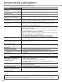
• Panasonic Air-to-Water is a split system, consisting of two units: indoor and outdoor units. The indoor unit consist of the
hydromodule and 200L sanitary water tank.
• These operating instructions describe how to operate the system using the indoor and outdoor units.
• As for the operation of other products such as radiator, external thermo controller, and underfl oor units, refer to the operating
instructions of each product.
• System could be locked to operate in HEAT mode and disable COOL mode.
• Some functions described in this manual may not be applicable to your system.
• Must use water that complies with European water quality standard 98/83 EC. The lifespan of the Tank Unit will be shorter if
groundwater (include spring water and well water) is used.
• The Tank Unit shall not be used with the tap water containing contaminants such as salt, acid, and other impurities which may
corrode the tank and its component.
• Consult your nearest authorised dealer for further information.
*
1
The system is locked to operate without COOL mode. It can be unlocked only by authorised installers or our authorised service
partners.
*
2
Only displayed when COOL mode is unlocked (This means when COOL mode is available)
3
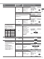
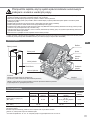
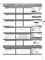
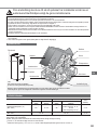
Operating conditions
WH-UD series WH-UX series
*
1
COOLING
(CIRCUIT)
HEATING
(TANK)
HEATING
(CIRCUIT)
HEATING
(TANK)
HEATING
(CIRCUIT)
Water outlet temperature (°C)
(Min. / Max.)
- / 65 *
3
20 / 55 - / 65 *
3
20 / 55 (Below Ambient -15 °C) *
4
20 / 60 (Above Ambient -10 °C) *
4
5 / 20
Outdoor ambient temperature (°C)
(Min. / Max.)
-20 / 35 -28 / 35 16 / 43
When the outdoor temperature is out of the range in the table, the heating capacity will drop signifi cantly and the outdoor unit may
stop operating for its protection.
The unit will restart automatically after the outdoor temperature returns to the specifi ed range.
*
3
Above 55 °C, only possible with backup heater operation.
*
4
Between outdoor ambient -10 °C and -15 °C, the water outlet temperature gradually decreases from 60 °C to 55 °C.
EN
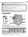
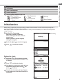
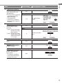
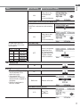
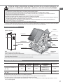
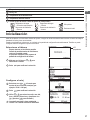
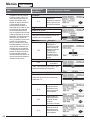
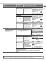
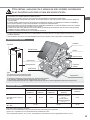
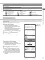
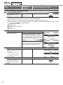
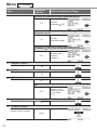
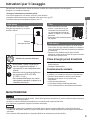
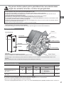
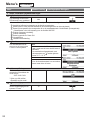
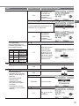
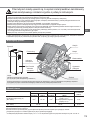
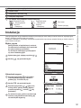
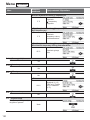
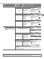
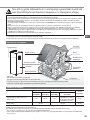
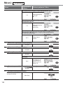
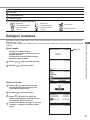
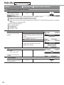
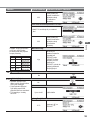
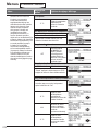
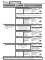
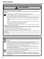
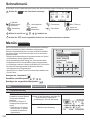
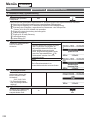
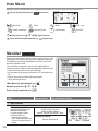
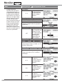
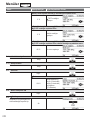
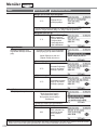
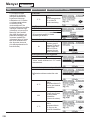
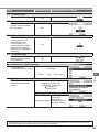
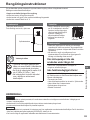
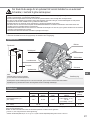
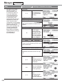
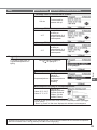
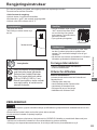
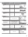
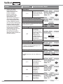
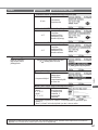
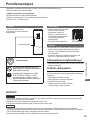
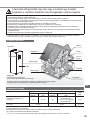
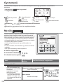
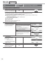
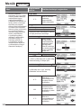
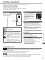
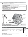
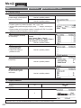
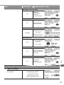
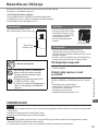
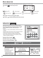
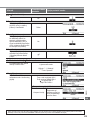
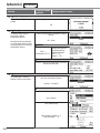
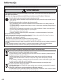
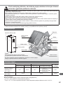
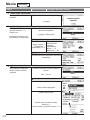
System overview
Radiator
Shower
Fan Coil
Unit
Floor
Heating
Outdoor Unit
Solar Panel
Power Supply
The illustrations in this manual are for explanation purposes only and may differ from the actual unit.
They are subject to change without notice for future improvement.
Note:
Not recommended to open the Front Plate.
(For authorised dealer/specialist use only)
Indoor Unit
Front Plate
Remote Controller

4
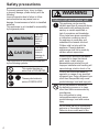
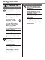
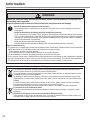
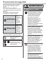
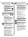
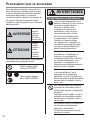
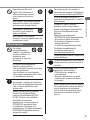
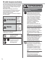
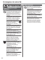
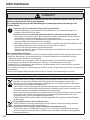
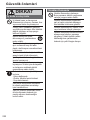
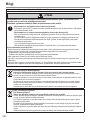
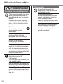
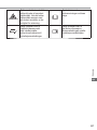
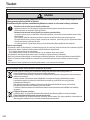
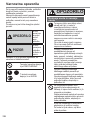
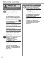
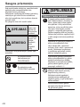
Safety precautions
To prevent personal injury, injury to others
or property damage, please comply with the
following:
Incorrect operation due to failure to follow
instructions below may cause harm or
damage, the seriousness of which is classifi ed
as below:
This appliances is not intended for accessibility
by the general public.
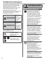
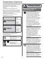
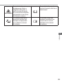
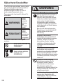
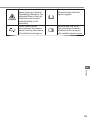
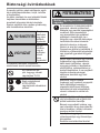
WARNING
This sign
warns of
death or
serious
injury.
CAUTION
This sign
warns of
injury or
damage to
property.
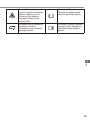
The instructions to be followed are classifi ed
by the following symbols:
This symbol denotes an
action that is PROHIBITED.
These symbols denote
actions COMPULSORY.
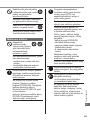
WARNING
Indoor unit and outdoor unit
This appliance can be used by
children aged from 8 years and above
and persons with reduced physical,
sensory or mental capabilities or
lack of experience and knowledge
if they have been given supervision
or instruction concerning use of
the appliance in a safe way and
understand the hazards involved.
Children shall not play with the
appliance. Cleaning and user
maintenance shall not be made by
children without supervision.
Please consult an authorised dealer
or specialist to clean the internal
parts, repair, install, remove,
disassemble and reinstall the unit.
Improper installation and handling will
cause leakage, electric shock or fi re.
Confi rm with authorised dealer or
specialist on usage of any specifi ed
refrigerant type. Using refrigerant type
other than the specifi ed may cause
product damage, burst and injury etc.
Do not use means to accelerate
the defrosting process or to clean,
other than those recommended by
manufacturer.
Any unfi t method or using
incompatible material may cause
product damage, burst and serious
injury.
Do not install the unit in a potentially
explosive or fl ammable atmosphere.
Failure to do so could result in fi re.

5
Do not insert your fi ngers or
other objects into the Air to
water indoor or outdoor unit,
rotating parts may cause injury.
Do not touch the outdoor unit during
lightning, it may cause electric shock.
Do not sit or step on the unit,
you may fall down accidentally.
Do not install the indoor unit outdoors.
This is designed for indoor installation
only.
Power supply
Do not use a modifi ed
cord, joint cord,
extension cord or
unspecifi ed cord to
prevent overheating
and fi re.
To prevent overheating, fi re or electric
shock:
• Do not share the same power outlet
with other equipment.
• Do not operate with wet hands.
• Do not over bend the power supply
cord.
If the supply cord is damaged, it must
be replaced by the manufacturer,
service agent or similarly qualifi ed
persons in order to avoid a hazard.
This unit is equipped with Residual
Current Circuit Breaker/Earth
Leakage Circuit Breaker (RCCB/
ELCB). Ask an authorised dealer
to check RCCB/ELCB operation
regularly, especially after installation,
inspection, and maintenance. RCCB/
ELCB malfunction may result in
electric shock and/or fi re.
It is strongly recommended that Install
Residual Current Device (RCD)
on-site to prevent electric shock and/
or fi re.
Before obtaining access to
terminals, all supply circuits must be
disconnected.
Stop using the product if any
abnormality/failure occurs and
disconnect the power supply.
(Risk of smoke/fi re/electric
shock)
Examples of abnormality/failure
• RCCB/ELCB trips frequently.
• Burning smell is observed.
• Abnormal noise or vibration of the
unit is observed.
• Hot water leaks from the indoor unit.
Contact your local dealer immediately
for maintenance/repair.
Wear gloves during inspection and
maintenance.
This equipment must be earthed to
prevent electrical shock or fi re.
Prevent electric shock by switching off
the power supply:
-Before cleaning or servicing,
-When extended non-use.
This appliance is for multiple uses. To
avoid electric shock, burn and/or fatal
injury, make sure to disconnect all
power supplies before accessing any
terminal in the indoor unit.
EN
Safety precautions

6
Safety precautions
CAUTION
Indoor unit and outdoor unit
Do not wash the indoor unit with
water, benzine, thinner or scouring
powder to avoid damage or corrosion
at the unit.
Do not install the unit close to
any combustibles or at bathroom.
Otherwise, it may cause electric
shock and/or fi re.
Do not touch the sharp
aluminium fi n, sharp parts
may cause injury.
Do not use the system during
sterilisation in order to prevent
scalding with hot water, or
overheating of shower.
Do not dismantle the unit for cleaning
purpose to avoid injury.
Do not step onto an unstable bench
when cleaning the unit to avoid injury.
Do not place a vase or water
container on the unit. Water may enter
the unit and degrade the insulation.
This may cause an electric shock.
Prevent water leakage by ensuring
drainage pipe is:
-Connected properly,
-Kept clear of gutters and containers,
or
-Not immersed in water
After a long period of use or use with
any combustible equipment, aerate
the room regularly.
After a long period of use, make
sure the installation rack does not
deteriorate to prevent the unit from
falling down.
Remote Controller
Do not wet the Remote Controller.
Failure to do so may result in electric
shock and/or fi re.
Do not press the buttons on the
Remote Controller using hard and
sharp objects. Failure to do so may
cause damage to the unit.
Do not wash the Remote Controller
using water, benzine, thinner or
scouring powder.
Do not inspect or maintain the
Remote Controller by yourself.
Consult an authorised dealer in order
to prevent personal injury caused by
incorrect operation.

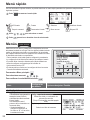
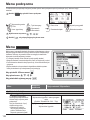
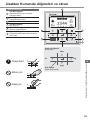
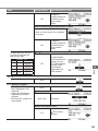
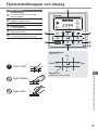
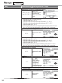
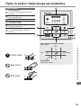
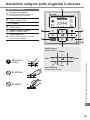
7
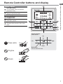
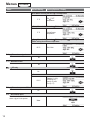
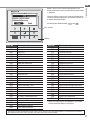
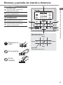
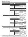
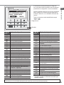
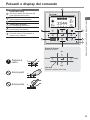
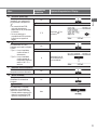
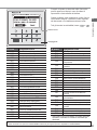
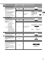
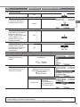
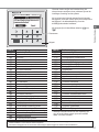
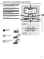
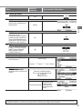
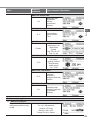
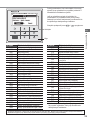
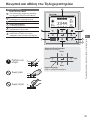
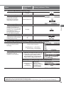
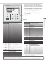
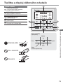
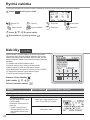
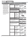
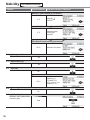
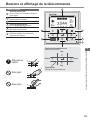
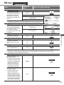
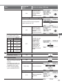
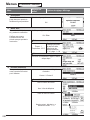
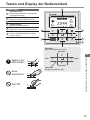
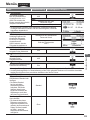
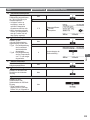
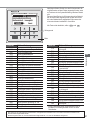
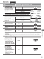
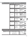
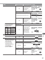
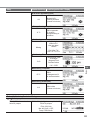
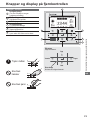
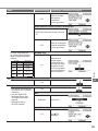
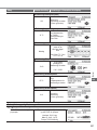
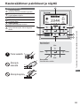
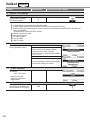
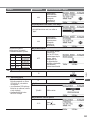
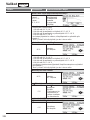
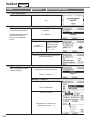
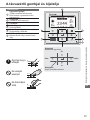
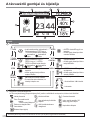
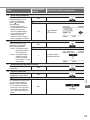
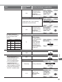
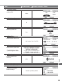
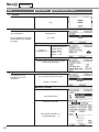
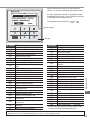
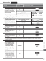
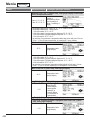
Remote Controller buttons and display
Buttons / Indicator
1
Quick Menu button
(For more details, refer to the separate
Quick Menu Guide.)
2
Back button
Returns to the previous screen
3 LCD Display
4
Main Menu button
For function setup
5
ON/OFF button
Starts/Stops operation
6
Operation indicator
Illuminates during operation, blinks during
alarm.
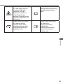
Press centre
No glove
No pen
2
1
4
5
6
3
Cross key buttons
Selects an item.
Enter button
Fixes the selected content.
Up
Down
Left Right
Safety precautions / Remote Controller buttons and display
EN

8
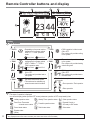
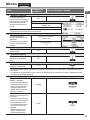
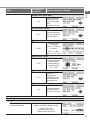
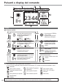
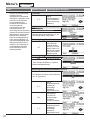
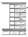
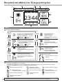
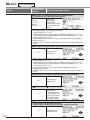
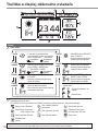
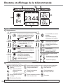
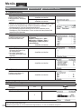
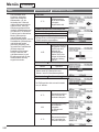
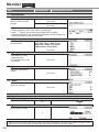
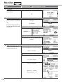
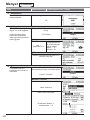
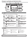
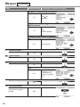
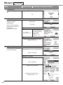
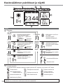
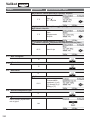
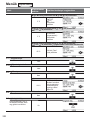
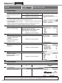
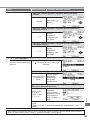
Remote Controller buttons and display
Display
1 Mode selection
*
1,
*
2
AUTO
• Depending on the preset outdoor
temperature, the system selects
HEAT or *
1,
*
2
COOL operation
mode.
Auto Heat Auto Cool
*
1,
*
2
COOL • COOL operation is either turned
ON or OFF.
• The outdoor unit provides cooling
to the system.
*
1,
*
2
AUTO
+ TANK
• Depending on the preset outdoor
temperature, the system selects
HEAT + TANK or *
1,
*
2
COOL +
TANK operation mode.
Auto Heat Auto Cool
*
1,
*
2
COOL
+ TANK
• The outdoor unit provides cooling
to the system.
• The outdoor unit provides heating
when boiling tank.
HEAT
• HEAT operation is either turned
ON or OFF.
• The outdoor unit provides heat to
the system.
TANK
• TANK operation is either turned
ON or OFF.
• The outdoor unit provides heat to
the water tank.
HEAT
+ TANK
• The outdoor unit provides heat to
the water tank and the system.
• This mode can be selected only
when the water tank is installed.
* The direction icons point to the currently
active mode.
• Room operation / Tank operation.
• Deice operation.
2
Operation icons
The status of operation is displayed.
Icon will not display (under operation OFF screen) whenever operation is OFF except weekly timer.
Holiday operation status Weekly Timer operation status Quiet operation status
Zone: Room Thermostat
→Internal sensor status
Powerful operation status
Demand Control or
SG ready or SHP status
Room Heater status Tank Heater status Solar status
Bivalent status
(Boiler)
*
1
The system is locked to operate without COOL mode. It can be unlocked only by authorised installers or our authorised service partners.
*
2
Only displayed when COOL mode is unlocked (This means when COOL mode is available).
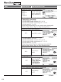
2 43
1
5
6
7

9
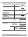
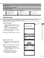
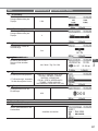
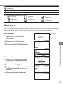
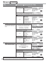
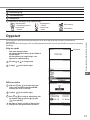
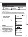
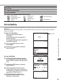
Initialization
Before starting to install the various menu settings, please initiate the Remote Controller by selecting the language of
operation and installing the date and time correctly.
When power is turned on for the fi rst time, it becomes the setting screen automatically. It can also be set from personal
setting of the menu.
Selecting the language
LCD blinking
Wait while the display is initializing.
When initializing screen ends, it turns to
normal screen.
When any button is pressed, language
setting screen appears.
1
Scroll with
and to select the language.
2
Press to confi rm the selection.
Setting the clock
1
Select with
or how to display the time,
either 24h or am/pm format (for example, 15:00
or 3:00 pm).
2
Press to confi rm the selection.
3
Use
and to select year, month, day, hour
and minutes. (Select and move with and
press to confi rm.)
4
Once the time is set, time and day will appear
on the display even if the Remote Controller is
turned OFF.
3 Temperature of each zone
4 Time and day
5 Water Tank temperature
6 Outdoor temperature
7 Sensor type/Set temperature type icons
Water Temperature
→Compensation curve
Water Temperature
→Direct
Pool only
Room Thermostat
→External
Room Thermostat
→Internal
Room Thermistor
EN
Remote Controller buttons and display / Initialization

10
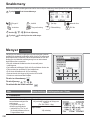
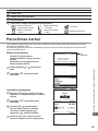
Menus
For user
Select menus and determine settings according to the system
available in the household. All initial settings must be done by an
authorised dealer or a specialist. It is recommended that all alterations
of the initial settings are also done by an authorised dealer or a
specialist.
• After initial installation, you may manually adjust the settings.
• The initial setting remains active until the user changes it.
• The Remote Controller can be used for multiple installations.
• Ensure the operation indicator is OFF before setting.
• The system may not work properly if set wrongly.
Please consult an authorised dealer.
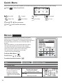
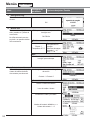
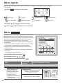
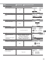
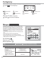
To display <Main Menu>:
To select menu:
To confi rm the selected content:
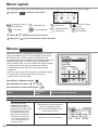
After the initial settings have been completed, you can select a quick menu from the following options and edit the setting.
1
Press
to display the quick menu.
Force DHW Powerful Quiet Force Heater
Weekly Timer Force Defrost Error Reset R/C Lock
2
Use to select menu.
3
Press to turn on/off the select menu.
Quick Menu
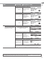
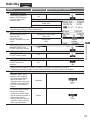
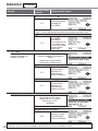
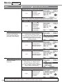
Menu Default Setting Setting Options / Display
1 Function setup
1.1
Weekly timer
Once the weekly timer is set up,
User can edit from Quick Menu.
To set up to 6 patterns of
operation on a daily basis.
• Disabled if Heat-Cool SW is
select “Yes” or if Force Heater
is on.
Timer setup
Select day of the week and
set the patterns needed
(Time / Operation ON/OFF / Mode)
Timer copy
Select day of the week

11
Menu Default Setting Setting Options / Display
1.2
Holiday timer
To save energy, a holiday
period may be set to either turn
OFF the system or lower the
temperature during the period.
OFF
ON
Holiday start and end.
Date and time
OFF or lowered temperature
• Weekly timer setting may be temporarily disabled during Holiday timer setting
but it will be restored once the Holiday timer is completed.
1.3
Quiet timer
To operate quietly during the
preset period.
6 patterns may be set.
Level 0 means the mode is off.
Time to start Quiet :
Date and time
Level of quietness:
0 ~ 3
1.4
Room heater
To set the room heater ON or
OFF.
OFF
1.5
Tank heater
To set the tank heater ON or
OFF.
OFF
1.6
Sterilization
To set the auto sterilization ON
or OFF.
ON
• Do not use the system during sterilization in order to prevent scalding with hot water, or overheating of shower.
• Ask an authorised dealer to determine the level of sterilization function fi eld settings according to the local laws and
regulations.
1.7
DHW mode (Domestic Hot Water)
To set the DHW mode to
Standard or Smart.
• Standard mode have faster
DHW Tank heat up time.
Meanwhile Smart mode
take longer time to heat up
DHW time with lower energy
consumption.
Standard
To set the tank sensor to Top
or Center.
• Selection of the tank sensor
to top slow down the start of
boiling up the tank and reduce
power consumption.
Please change this selection
to “Center” when the hot water
becomes insuffi cient.
Top
Menus
For user
EN
Quick Menu / Menus

12
Menus
For user
Menu Default Setting Setting Options / Display
2 System check
2.1
Energy monitor
Present or historical chart of
energy consumption, generation
or COP.
Present
Select and retrieve
Historical chart
Select and retrieve
• COP= Coeffi cient of Performance.
• For historical chart, the period is selected from 1 day/1 week/1year.
• Energy consumption (kWh) of heating, *
1,
*
2
cooling, tank and total may be
retrieved.
• The total power consumption is an estimated value based on AC 230 V and
may differ from value measured by precise equipment.
2.2
System information
Shows all system information in
each area.
Actual system information of 10 items:
Inlet / Outlet / Zone 1 / Zone 2 / Tank /
Buffer tank / Solar / Pool / COMP
frequency / Pump fl owrate
Select and retrieve
2.3
Error history
• Refer to Troubleshooting for
error codes.
• The most recent error code is
displayed at the top.
Select and retrieve
2.4
Compressor
Shows the compressor
performance.
Select and retrieve
2.5
Heater
Total hours of ON time for
Room heater/Tank heater.
Select and retrieve
3 Personal setup
3.1
Touch sound
Turns the operation sound ON/
OFF.
ON
3.2
LCD contrast
Sets the screen contrast.
3
*
1
The system is locked to operate without COOL mode. It can be unlocked only by authorised installers or our authorised service partners.
*
2
Only displayed when COOL mode is unlocked (This means when COOL mode is available).

13
Menu Default Setting Setting Options / Display
3.3
Backlight
Sets the duration of screen
backlight.
1 min
3.4
Backlight intensity
Sets screen backlight
brightness.
4
3.5
Clock format
Sets the type of clock display.
24h
3.6
Date & Time
Sets the present date and time.
Year / Month / Day / Hour / Min
3.7
Language
Sets the display language for
the top screen.
• For Greek, please refer to the
English version.
ENGLISH / FRANÇAIS / DEUTSCH /
ITALIANO / ESPAÑOL / DANISH /
SWEDISH / NORWEGIAN /
POLISH / CZECH / NEDERLANDS /
TÜRKÇE / SUOMI / MAGYAR /
SLOVENŠČINA / HRVATSKI / LIETUVIŲ
3.8
Unlock password
4 digit password for all the
settings.
0000
4 Service contact
4.1
Contact 1 / Contact 2
Preset contact number for
installer.
Select and retrieve
EN
Menus

14
Menus
For installer
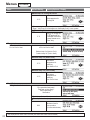
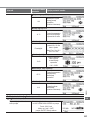
Menu Default Setting Setting Options / Display
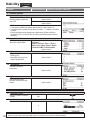
5 Installer setup System setup
5.1
Optional PCB connectivity
To connect to the external PCB
required for servicing.
No
• If the external PCB is connected (optional), the system will have following additional functions:
1
Buffer tank connection and control over its function and temperature.
2
Control over 2 zones (including the swimming pool and the function to heat water in it).
3
Solar function (the solar thermal panels connected to either the DHW (Domestic Hot Water) Tank or the Buffer Tank.
• DHW is not applicable for WH-ADC *models.
4
External compressor switch.
5
External error signal.
6
SG ready control.
7
Demand control.
8
Heat-Cool SW
5.2
Zone & Sensor
To select the sensors and to
select either 1 zone or 2 zone
system.
Zone
• After selecting 1 or 2 zone system, proceed
to the selection of room or swimming pool.
• If the swimming pool is selected, the
temperature must be selected for
T temperature between 0°C ~ 10 °C.
Sensor
* For room thermostat, there is a further
selection of external or internal.
5.3
Heater capacity
To reduce the heater power if
unnecessary.*
3 kW / 6 kW / 9kW
* Options of kW vary depending
on the model.
5.4
Anti freezing
To activate or deactivate the
water freeze prevention when
the system is OFF
Yes

15
Menu Default Setting Setting Options / Display
5.5
Buffer tank connection
To connect tank to the system
and if selected YES, to set
T temperature.
• The optional PCB connectivity
must be selected YES to
enable the function.
• If the optional PCB
connectivity is not selected,
the function will not appear on
the display.
No
Yes
5 °C
Set T for Buffer
Tank
5.6
Base pan heater
To select whether or not
optional base pan heater is
connected.
* Type A - The base pan heater
activates only during
deice operation.
* Type B -The base pan heater
activates when outdoor
ambient temperature is
5 °C or lower.
No
Yes
A
Set base pan heater
type*.
5.7
Alternative outdoor sensor
To select an alternative outdoor
sensor.
No
5.8
Bivalent connection
To select to enable or disable
bivalent connection.
No
Yes
To select either auto control
pattern or SG ready input
control pattern.
* This selection only display
to select when optional pcb
connection set to Yes.
Auto
EN
Menus

16
Menus
For installer
Menu Default Setting Setting Options / Display
To select a bivalent connection
to allow an additional heat
source such as a boiler to heat-
up the buffer tank and domestic
hot water tank when heatpump
capacity is insuffi cient at low
outdoor temperature. The
bivalent feature can be set-up
either in alternative mode
(heatpump and boiler operate
alternately), or in parallel
mode (both heatpump and
boiler operate simultaneously),
or in advance parallel mode
(heatpump operates and boiler
turns on for buffer-tank and/or
domestic hot water depending
on the control pattern setting
options).
Yes Auto
-5 °C
Set outdoor
temperature for
turn ON Bivalent
connection.
Yes After selecting the outdoor temperature
Control pattern
Alternative / Parallel / Advanced parallel
• Select advanced parallel for bivalent use of
the tanks.
Control pattern
Alternative
OFF
Option to set external
pump either ON or
OFF during bivalent
operation. Set to ON
if system is simple
bivalent connection.
Control pattern Advanced parallel
Heat Selection of the tank
• “Heat” implies Buffer Tank and “DHW”
implies Domestic Hot Water Tank.
Control pattern
Advanced parallel Heat Yes
• Buffer Tank is activated only after selecting
“Yes”.
-8 °C
Set the temperature
threshold to start the
bivalent heat source.
0:30
Delay timer to start
the bivalent heat
source
(in hour and minutes).
-2 °C
Set the temperature
threshold to stop the
bivalent heat source.

17
Menu Default Setting Setting Options / Display
0:30
Delay timer to stop
the bivalent heat
source
(in hour and minutes).
Control pattern Advanced parallel DHW Yes
• DHW Tank is activated only after selecting
“Yes”.
0:30
Delay timer to start
the bivalent heat
source
(in hour and minutes).
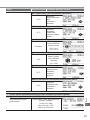
SG ready input control for
bivalent system follow below
input condition.
Yes SG ready
OFF
Option to set external
pump either ON or
OFF during bivalent
operation. Set to ON
if system is simple
bivalent connection.
SG signal Operation pattern
Vcc-bit1 Vcc-bit2
Open Open
Heat Pump OFF,
Boiler OFF
Short Open
Heat Pump ON,
Boiler OFF
Open Short
Heat Pump OFF,
Boiler ON
Short Short
Heat Pump ON,
Boiler ON
5.9
External SW
No
5.10
Solar connection
• The optional PCB connectivity
must be selected YES to
enable the function.
• If the optional PCB
connectivity is not selected,
the function will not appear on
the display.
• DHW is not applicable for
WH-ADC *models.
No
Yes
Buffer tank Selection of the tank
Yes After selecting the tank
10 °C
Set
T ON
temperature
EN
Menus

18
Menus
For installer
Menu Default Setting Setting Options / Display
Yes After selecting the tank T ON temperature
5 °C
Set
T OFF
temperature
Yes After selecting the tank T ON temperature T OFF temperature
5 °C
Set Antifreeze
temperature
Yes After selecting the tank T ON temperature T OFF temperature
After setting the antifreeze temperature
80 °C Set Hi limit
5.11
External error signal
No
5.12
Demand control
No
5.13
SG ready
No
Yes
120 %
Capacity (1) & (2)
of DHW (in %),
Heat (in %) and
Cool (in °C)
5.14
External compressor SW
No
5.15
Circulation liquid
To select whether to circulate
water or glycol in the system.
Water

19
*
1
The system is locked to operate without COOL mode. It can be unlocked only by authorised installers or our authorised service partners.
*
2
Only displayed when COOL mode is unlocked (This means when COOL mode is available).
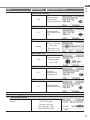
Menu Default Setting Setting Options / Display
5.16
Heat-Cool SW
No
5.17
Force heater
To turn on Force heater either
manually (by default) or
automatically.
Manual
5.18
Defrost signal
To turn on defrost signal to stop
fan coil during defrost operation.
(If defrost signal set to yes,
bivalent function will not
available to use)
No
5.19
Pump fl owrate
To set variable fl ow pump
control or fi x pump duty control.
T
6 Installer setup Operation setup
To access to the four major
functions or modes.
4 main modes
Heat / *
1,
*
2
Cool / *
1,
*
2
Auto / Tank
6.1
Heat
To set various water & ambient
temperatures for heating.
Water temp. for heating ON /
Outdoor temp. for heating OFF /
T for heating ON /
Heater ON/OFF
Water temp. for heating ON
Compensation curve
Heating ON
temperatures in
compensation curve
or direct input.
EN
Menus

20
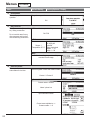
Menus
For installer
Menu Default Setting Setting Options / Display
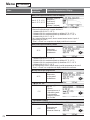
Water temp. for heating ON Compensation curve
X axis: -5 °C, 15 °C
Y axis: 55 °C, 35 °C
Input the 4
temperature points
(2 on horizontal X
axis, 2 on vertical Y
axis).
• Temperature range: X axis: -20 °C ~ 15 °C, Y axis: See below
• Temperature range for the Y axis input:
1. WH-UD model: 20 °C ~ 60 °C
2. WH-UH model & Back up heater is enabled: 25 °C ~ 65 °C
3. WH-UH model & Back up heater is disabled: 35 °C ~ 65 °C
4. WH-UX model: 20 °C ~ 60 °C
• If 2 zone system is selected, the 4 temperature points must also be input for Zone
2.
• “Zone 1” and “Zone 2” will not appear on the display if only 1 zone system.
Water temp. for heating ON Direct
35 °C
Temperature for
heating ON
• Min. ~ Max. range is conditional as follows:
1. WH-UD model: 20 °C ~ 60 °C
2. WH-UH model & Back up heater is enabled: 25 °C ~ 65 °C
3. WH-UH model & Back up heater is disabled: 35 °C ~ 65 °C
4. WH-UX model: 20 °C ~ 60 °C
• If 2 zone system is selected, temperature set point must input for Zone 2.
• “Zone 1” and “Zone 2” will not appear on the display if only 1 zone system.
Outdoor temp. for heating OFF
24 °C
Temperature for
heating OFF
T for heating ON
5 °C
Set
T for heating
ON.
* This setting will not
available to set when
pump fl owrate set to
Max. duty.
Heater ON/OFF
Heater ON/OFF Outdoor temp. for heater ON
0 °C
Temperature for
heater ON
Sidan laddas...
Sidan laddas...
Sidan laddas...
Sidan laddas...
Sidan laddas...
Sidan laddas...
Sidan laddas...
Sidan laddas...
Sidan laddas...
Sidan laddas...
Sidan laddas...
Sidan laddas...
Sidan laddas...
Sidan laddas...
Sidan laddas...
Sidan laddas...
Sidan laddas...
Sidan laddas...
Sidan laddas...
Sidan laddas...
Sidan laddas...
Sidan laddas...
Sidan laddas...
Sidan laddas...
Sidan laddas...
Sidan laddas...
Sidan laddas...
Sidan laddas...
Sidan laddas...
Sidan laddas...
Sidan laddas...
Sidan laddas...
Sidan laddas...
Sidan laddas...
Sidan laddas...
Sidan laddas...
Sidan laddas...
Sidan laddas...
Sidan laddas...
Sidan laddas...
Sidan laddas...
Sidan laddas...
Sidan laddas...
Sidan laddas...
Sidan laddas...
Sidan laddas...
Sidan laddas...
Sidan laddas...
Sidan laddas...
Sidan laddas...
Sidan laddas...
Sidan laddas...
Sidan laddas...
Sidan laddas...
Sidan laddas...
Sidan laddas...
Sidan laddas...
Sidan laddas...
Sidan laddas...
Sidan laddas...
Sidan laddas...
Sidan laddas...
Sidan laddas...
Sidan laddas...
Sidan laddas...
Sidan laddas...
Sidan laddas...
Sidan laddas...
Sidan laddas...
Sidan laddas...
Sidan laddas...
Sidan laddas...
Sidan laddas...
Sidan laddas...
Sidan laddas...
Sidan laddas...
Sidan laddas...
Sidan laddas...
Sidan laddas...
Sidan laddas...
Sidan laddas...
Sidan laddas...
Sidan laddas...
Sidan laddas...
Sidan laddas...
Sidan laddas...
Sidan laddas...
Sidan laddas...
Sidan laddas...
Sidan laddas...
Sidan laddas...
Sidan laddas...
Sidan laddas...
Sidan laddas...
Sidan laddas...
Sidan laddas...
Sidan laddas...
Sidan laddas...
Sidan laddas...
Sidan laddas...
Sidan laddas...
Sidan laddas...
Sidan laddas...
Sidan laddas...
Sidan laddas...
Sidan laddas...
Sidan laddas...
Sidan laddas...
Sidan laddas...
Sidan laddas...
Sidan laddas...
Sidan laddas...
Sidan laddas...
Sidan laddas...
Sidan laddas...
Sidan laddas...
Sidan laddas...
Sidan laddas...
Sidan laddas...
Sidan laddas...
Sidan laddas...
Sidan laddas...
Sidan laddas...
Sidan laddas...
Sidan laddas...
Sidan laddas...
Sidan laddas...
Sidan laddas...
Sidan laddas...
Sidan laddas...
Sidan laddas...
Sidan laddas...
Sidan laddas...
Sidan laddas...
Sidan laddas...
Sidan laddas...
Sidan laddas...
Sidan laddas...
Sidan laddas...
Sidan laddas...
Sidan laddas...
Sidan laddas...
Sidan laddas...
Sidan laddas...
Sidan laddas...
Sidan laddas...
Sidan laddas...
Sidan laddas...
Sidan laddas...
Sidan laddas...
Sidan laddas...
Sidan laddas...
Sidan laddas...
Sidan laddas...
Sidan laddas...
Sidan laddas...
Sidan laddas...
Sidan laddas...
Sidan laddas...
Sidan laddas...
Sidan laddas...
Sidan laddas...
Sidan laddas...
Sidan laddas...
Sidan laddas...
Sidan laddas...
Sidan laddas...
Sidan laddas...
Sidan laddas...
Sidan laddas...
Sidan laddas...
Sidan laddas...
Sidan laddas...
Sidan laddas...
Sidan laddas...
Sidan laddas...
Sidan laddas...
Sidan laddas...
Sidan laddas...
Sidan laddas...
Sidan laddas...
Sidan laddas...
Sidan laddas...
Sidan laddas...
Sidan laddas...
Sidan laddas...
Sidan laddas...
Sidan laddas...
Sidan laddas...
Sidan laddas...
Sidan laddas...
Sidan laddas...
Sidan laddas...
Sidan laddas...
Sidan laddas...
Sidan laddas...
Sidan laddas...
Sidan laddas...
Sidan laddas...
Sidan laddas...
Sidan laddas...
Sidan laddas...
Sidan laddas...
Sidan laddas...
Sidan laddas...
Sidan laddas...
Sidan laddas...
Sidan laddas...
Sidan laddas...
Sidan laddas...
Sidan laddas...
Sidan laddas...
Sidan laddas...
Sidan laddas...
Sidan laddas...
Sidan laddas...
Sidan laddas...
Sidan laddas...
Sidan laddas...
Sidan laddas...
Sidan laddas...
Sidan laddas...
Sidan laddas...
Sidan laddas...
Sidan laddas...
Sidan laddas...
Sidan laddas...
Sidan laddas...
Sidan laddas...
Sidan laddas...
Sidan laddas...
Sidan laddas...
Sidan laddas...
Sidan laddas...
Sidan laddas...
Sidan laddas...
Sidan laddas...
Sidan laddas...
Sidan laddas...
Sidan laddas...
Sidan laddas...
Sidan laddas...
Sidan laddas...
Sidan laddas...
Sidan laddas...
Sidan laddas...
Sidan laddas...
Sidan laddas...
Sidan laddas...
Sidan laddas...
Sidan laddas...
Sidan laddas...
Sidan laddas...
Sidan laddas...
Sidan laddas...
Sidan laddas...
Sidan laddas...
Sidan laddas...
Sidan laddas...
Sidan laddas...
Sidan laddas...
Sidan laddas...
Sidan laddas...
Sidan laddas...
Sidan laddas...
Sidan laddas...
Sidan laddas...
Sidan laddas...
Sidan laddas...
Sidan laddas...
Sidan laddas...
Sidan laddas...
Sidan laddas...
Sidan laddas...
Sidan laddas...
Sidan laddas...
Sidan laddas...
Sidan laddas...
Sidan laddas...
Sidan laddas...
Sidan laddas...
Sidan laddas...
Sidan laddas...
Sidan laddas...
Sidan laddas...
Sidan laddas...
Sidan laddas...
Sidan laddas...
Sidan laddas...
Sidan laddas...
Sidan laddas...
Sidan laddas...
Sidan laddas...
Sidan laddas...
Sidan laddas...
Sidan laddas...
Sidan laddas...
Sidan laddas...
Sidan laddas...
Sidan laddas...
Sidan laddas...
Sidan laddas...
Sidan laddas...
Sidan laddas...
Sidan laddas...
Sidan laddas...
Sidan laddas...
Sidan laddas...
Sidan laddas...
Sidan laddas...
Sidan laddas...
Sidan laddas...
Sidan laddas...
Sidan laddas...
Sidan laddas...
Sidan laddas...
Sidan laddas...
Sidan laddas...
Sidan laddas...
Sidan laddas...
Sidan laddas...
Sidan laddas...
Sidan laddas...
Sidan laddas...
Sidan laddas...
Sidan laddas...
Sidan laddas...
Sidan laddas...
Sidan laddas...
Sidan laddas...
Sidan laddas...
Sidan laddas...
Sidan laddas...
Sidan laddas...
Sidan laddas...
Sidan laddas...
Sidan laddas...
Sidan laddas...
Sidan laddas...
Sidan laddas...
Sidan laddas...
Sidan laddas...
Sidan laddas...
Sidan laddas...
Sidan laddas...
Sidan laddas...
Sidan laddas...
Sidan laddas...
Sidan laddas...
Sidan laddas...
Sidan laddas...
Sidan laddas...
Sidan laddas...
Sidan laddas...
Sidan laddas...
Sidan laddas...
Sidan laddas...
Sidan laddas...
Sidan laddas...
Sidan laddas...
Sidan laddas...
Sidan laddas...
Sidan laddas...
Sidan laddas...
Sidan laddas...
Sidan laddas...
Sidan laddas...
Sidan laddas...
Sidan laddas...
Sidan laddas...
Sidan laddas...
Sidan laddas...
Sidan laddas...
Sidan laddas...
Sidan laddas...
Sidan laddas...
Sidan laddas...
Sidan laddas...
Sidan laddas...
Sidan laddas...
Sidan laddas...
Sidan laddas...
Sidan laddas...
Sidan laddas...
Sidan laddas...
Sidan laddas...
Sidan laddas...
Sidan laddas...
Sidan laddas...
Sidan laddas...
Sidan laddas...
Sidan laddas...
Sidan laddas...
Sidan laddas...
Sidan laddas...
Sidan laddas...
Sidan laddas...
Sidan laddas...
Sidan laddas...
Sidan laddas...
Sidan laddas...
Sidan laddas...
Sidan laddas...
Sidan laddas...
Sidan laddas...
Sidan laddas...
Sidan laddas...
Sidan laddas...
Sidan laddas...
Sidan laddas...
Sidan laddas...
Sidan laddas...
Sidan laddas...
Sidan laddas...
Sidan laddas...
Sidan laddas...
Sidan laddas...
Sidan laddas...
Sidan laddas...
Sidan laddas...
Sidan laddas...
Sidan laddas...
Sidan laddas...
Sidan laddas...
Sidan laddas...
Sidan laddas...
Sidan laddas...
Sidan laddas...
Sidan laddas...
Sidan laddas...
Sidan laddas...
Sidan laddas...
Sidan laddas...
Sidan laddas...
Sidan laddas...
Sidan laddas...
Sidan laddas...
Sidan laddas...
Sidan laddas...
Sidan laddas...
Sidan laddas...
Sidan laddas...
Sidan laddas...
Sidan laddas...
Sidan laddas...
Sidan laddas...
Sidan laddas...
Sidan laddas...
Sidan laddas...
Sidan laddas...
Sidan laddas...
Sidan laddas...
Sidan laddas...
Sidan laddas...
Sidan laddas...
Sidan laddas...
Sidan laddas...
Sidan laddas...
Sidan laddas...
Sidan laddas...
Sidan laddas...
Sidan laddas...
Sidan laddas...
Sidan laddas...
-
 1
1
-
 2
2
-
 3
3
-
 4
4
-
 5
5
-
 6
6
-
 7
7
-
 8
8
-
 9
9
-
 10
10
-
 11
11
-
 12
12
-
 13
13
-
 14
14
-
 15
15
-
 16
16
-
 17
17
-
 18
18
-
 19
19
-
 20
20
-
 21
21
-
 22
22
-
 23
23
-
 24
24
-
 25
25
-
 26
26
-
 27
27
-
 28
28
-
 29
29
-
 30
30
-
 31
31
-
 32
32
-
 33
33
-
 34
34
-
 35
35
-
 36
36
-
 37
37
-
 38
38
-
 39
39
-
 40
40
-
 41
41
-
 42
42
-
 43
43
-
 44
44
-
 45
45
-
 46
46
-
 47
47
-
 48
48
-
 49
49
-
 50
50
-
 51
51
-
 52
52
-
 53
53
-
 54
54
-
 55
55
-
 56
56
-
 57
57
-
 58
58
-
 59
59
-
 60
60
-
 61
61
-
 62
62
-
 63
63
-
 64
64
-
 65
65
-
 66
66
-
 67
67
-
 68
68
-
 69
69
-
 70
70
-
 71
71
-
 72
72
-
 73
73
-
 74
74
-
 75
75
-
 76
76
-
 77
77
-
 78
78
-
 79
79
-
 80
80
-
 81
81
-
 82
82
-
 83
83
-
 84
84
-
 85
85
-
 86
86
-
 87
87
-
 88
88
-
 89
89
-
 90
90
-
 91
91
-
 92
92
-
 93
93
-
 94
94
-
 95
95
-
 96
96
-
 97
97
-
 98
98
-
 99
99
-
 100
100
-
 101
101
-
 102
102
-
 103
103
-
 104
104
-
 105
105
-
 106
106
-
 107
107
-
 108
108
-
 109
109
-
 110
110
-
 111
111
-
 112
112
-
 113
113
-
 114
114
-
 115
115
-
 116
116
-
 117
117
-
 118
118
-
 119
119
-
 120
120
-
 121
121
-
 122
122
-
 123
123
-
 124
124
-
 125
125
-
 126
126
-
 127
127
-
 128
128
-
 129
129
-
 130
130
-
 131
131
-
 132
132
-
 133
133
-
 134
134
-
 135
135
-
 136
136
-
 137
137
-
 138
138
-
 139
139
-
 140
140
-
 141
141
-
 142
142
-
 143
143
-
 144
144
-
 145
145
-
 146
146
-
 147
147
-
 148
148
-
 149
149
-
 150
150
-
 151
151
-
 152
152
-
 153
153
-
 154
154
-
 155
155
-
 156
156
-
 157
157
-
 158
158
-
 159
159
-
 160
160
-
 161
161
-
 162
162
-
 163
163
-
 164
164
-
 165
165
-
 166
166
-
 167
167
-
 168
168
-
 169
169
-
 170
170
-
 171
171
-
 172
172
-
 173
173
-
 174
174
-
 175
175
-
 176
176
-
 177
177
-
 178
178
-
 179
179
-
 180
180
-
 181
181
-
 182
182
-
 183
183
-
 184
184
-
 185
185
-
 186
186
-
 187
187
-
 188
188
-
 189
189
-
 190
190
-
 191
191
-
 192
192
-
 193
193
-
 194
194
-
 195
195
-
 196
196
-
 197
197
-
 198
198
-
 199
199
-
 200
200
-
 201
201
-
 202
202
-
 203
203
-
 204
204
-
 205
205
-
 206
206
-
 207
207
-
 208
208
-
 209
209
-
 210
210
-
 211
211
-
 212
212
-
 213
213
-
 214
214
-
 215
215
-
 216
216
-
 217
217
-
 218
218
-
 219
219
-
 220
220
-
 221
221
-
 222
222
-
 223
223
-
 224
224
-
 225
225
-
 226
226
-
 227
227
-
 228
228
-
 229
229
-
 230
230
-
 231
231
-
 232
232
-
 233
233
-
 234
234
-
 235
235
-
 236
236
-
 237
237
-
 238
238
-
 239
239
-
 240
240
-
 241
241
-
 242
242
-
 243
243
-
 244
244
-
 245
245
-
 246
246
-
 247
247
-
 248
248
-
 249
249
-
 250
250
-
 251
251
-
 252
252
-
 253
253
-
 254
254
-
 255
255
-
 256
256
-
 257
257
-
 258
258
-
 259
259
-
 260
260
-
 261
261
-
 262
262
-
 263
263
-
 264
264
-
 265
265
-
 266
266
-
 267
267
-
 268
268
-
 269
269
-
 270
270
-
 271
271
-
 272
272
-
 273
273
-
 274
274
-
 275
275
-
 276
276
-
 277
277
-
 278
278
-
 279
279
-
 280
280
-
 281
281
-
 282
282
-
 283
283
-
 284
284
-
 285
285
-
 286
286
-
 287
287
-
 288
288
-
 289
289
-
 290
290
-
 291
291
-
 292
292
-
 293
293
-
 294
294
-
 295
295
-
 296
296
-
 297
297
-
 298
298
-
 299
299
-
 300
300
-
 301
301
-
 302
302
-
 303
303
-
 304
304
-
 305
305
-
 306
306
-
 307
307
-
 308
308
-
 309
309
-
 310
310
-
 311
311
-
 312
312
-
 313
313
-
 314
314
-
 315
315
-
 316
316
-
 317
317
-
 318
318
-
 319
319
-
 320
320
-
 321
321
-
 322
322
-
 323
323
-
 324
324
-
 325
325
-
 326
326
-
 327
327
-
 328
328
-
 329
329
-
 330
330
-
 331
331
-
 332
332
-
 333
333
-
 334
334
-
 335
335
-
 336
336
-
 337
337
-
 338
338
-
 339
339
-
 340
340
-
 341
341
-
 342
342
-
 343
343
-
 344
344
-
 345
345
-
 346
346
-
 347
347
-
 348
348
-
 349
349
-
 350
350
-
 351
351
-
 352
352
-
 353
353
-
 354
354
-
 355
355
-
 356
356
-
 357
357
-
 358
358
-
 359
359
-
 360
360
-
 361
361
-
 362
362
-
 363
363
-
 364
364
-
 365
365
-
 366
366
-
 367
367
-
 368
368
-
 369
369
-
 370
370
-
 371
371
-
 372
372
-
 373
373
-
 374
374
-
 375
375
-
 376
376
-
 377
377
-
 378
378
-
 379
379
-
 380
380
-
 381
381
-
 382
382
-
 383
383
-
 384
384
-
 385
385
-
 386
386
-
 387
387
-
 388
388
-
 389
389
-
 390
390
-
 391
391
-
 392
392
-
 393
393
-
 394
394
-
 395
395
-
 396
396
-
 397
397
-
 398
398
-
 399
399
-
 400
400
-
 401
401
-
 402
402
-
 403
403
-
 404
404
-
 405
405
-
 406
406
-
 407
407
-
 408
408
-
 409
409
-
 410
410
-
 411
411
-
 412
412
-
 413
413
-
 414
414
-
 415
415
-
 416
416
-
 417
417
-
 418
418
-
 419
419
-
 420
420
-
 421
421
-
 422
422
-
 423
423
-
 424
424
-
 425
425
-
 426
426
-
 427
427
-
 428
428
-
 429
429
-
 430
430
-
 431
431
-
 432
432
-
 433
433
-
 434
434
-
 435
435
-
 436
436
-
 437
437
-
 438
438
-
 439
439
-
 440
440
-
 441
441
-
 442
442
-
 443
443
-
 444
444
-
 445
445
-
 446
446
-
 447
447
-
 448
448
-
 449
449
-
 450
450
-
 451
451
-
 452
452
-
 453
453
-
 454
454
-
 455
455
-
 456
456
-
 457
457
-
 458
458
-
 459
459
-
 460
460
-
 461
461
-
 462
462
-
 463
463
-
 464
464
-
 465
465
-
 466
466
-
 467
467
-
 468
468
-
 469
469
-
 470
470
-
 471
471
-
 472
472
-
 473
473
-
 474
474
-
 475
475
-
 476
476
-
 477
477
-
 478
478
-
 479
479
-
 480
480
-
 481
481
-
 482
482
-
 483
483
-
 484
484


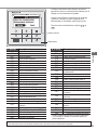
Panasonic WHADC1216H6E5C Bruksanvisningar
- Typ
- Bruksanvisningar
på andra språk
- italiano: Panasonic WHADC1216H6E5C Istruzioni per l'uso
- čeština: Panasonic WHADC1216H6E5C Operativní instrukce
- español: Panasonic WHADC1216H6E5C Instrucciones de operación
- Deutsch: Panasonic WHADC1216H6E5C Bedienungsanleitung
- polski: Panasonic WHADC1216H6E5C Instrukcja obsługi
- français: Panasonic WHADC1216H6E5C Mode d'emploi
- Türkçe: Panasonic WHADC1216H6E5C Kullanma talimatları
- English: Panasonic WHADC1216H6E5C Operating instructions
- suomi: Panasonic WHADC1216H6E5C Käyttö ohjeet
- Nederlands: Panasonic WHADC1216H6E5C Handleiding
Relaterade papper
-
Panasonic WHADC1216H6E5 Bruksanvisningar
-
-
-
-
-
-
-
-
-
Andra dokument
-
OK. OAC 100 Användarmanual
-
CTC Union EcoWater 302 Installationsguide
-
Quick BX 16 Användarmanual
-
-
Vaillant geoTHERM Bruksanvisning
-
Alber M25 E-MOTION Ergonomic Control System Bruksanvisningar
-
Hitachi DHWS200S-2.7H2E Användarmanual
-
Truma Combi 6 Operating Instructions Manual
-
Buderus HR 200 Installation Instructions Manual