OJ Electronics OJ-Zone-Module-MP Bruksanvisningar
- Typ
- Bruksanvisningar

OJ GreenZone™
Module MP-Bus
67465C 09/19 (BCH)
© 2015 OJ Electronics A/S
• English
• Deutsch
• Français
• Svenska
• Norsk
• Dansk
INSTRUCTIONS
GREEN COMFORT
Maximum comfort with low energy consumption

© 2019 OJ Electronics A/S
2
© 2019 OJ Electronics A/S
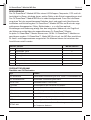
LIST OF FIGURES
The following figures are located at the back of the instructions:
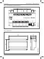
Fig. 1: OJ GreenZone™ Module MP-Bus
Fig. 2: Dimensions
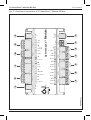
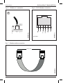
Fig. 3: Overview of connectors in OJ GreenZone™ Module MP-Bus
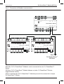
Fig. 4: Connection of Modbus communication
Fig. 5: “Modbus in” connector
Fig. 6: RJ12 Modbus connector
Fig. 7: Modbus cable connection
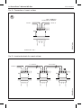
Fig. 8: Connection of supply voltage
Fig. 9: Looping terminals for supply voltage
Fig. 10: Connection of PT1000 and CO2 sensors
Fig. 10A: Connection of humidity sensor
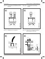
Fig. 11: Connection of temperature oset potentiometer
Fig. 12: Connection of frost thermostat
Fig. 13: “Modbus out” connector
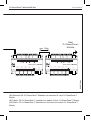
Fig. 14: Example of MP-Bus connection: exhaust VAV actuator
Fig. 14A: Example of MP-Bus connection: inlet VAV actuator
Fig. 15: Connection of PT1000 sensor, inlet
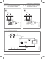
Fig. 16: Example of MP-Bus connection: heating valve actuator
Fig. 16A: Example of MP-Bus connection: cooling valve actuator
Fig. 17: 2-digit display
Fig. 18: RJ12 connector “Modbus sensor”
Fig. 19: Configuration overview
Fig. 20: Connection of window contact
Fig. 21: Connection of PIR sensor
INTRODUCTION
OJ GreenZone™ Module MP-Bus is an electronic controller for regulating a single VAV
zone in a ventilation system. OJ GreenZone™ Module MP-Bus contains all the functions
necessary for controlling the VAV zone optimally with regard to energy consumption and
comfort.
INSTRUCTIONS
English ................................................................................................................. 3 - 15
Deutsch ............................................................................................................... 16 - 29
Français .............................................................................................................. 30 - 43
Svenska .............................................................................................................. 44 - 56
Norsk ................................................................................................................... 57 - 69
Dansk.................................................................................................................. 70 - 82
ILLUSTRATIONS
Illustrations .......................................................................................................... 84 - 93

3
© 2019 OJ Electronics A/S
English
LIST OF FIGURES
The following figures are located at the back of the instructions:
Fig. 1: OJ GreenZone™ Module MP-Bus
Fig. 2: Dimensions
Fig. 3: Overview of connectors in OJ GreenZone™ Module MP-Bus
Fig. 4: Connection of Modbus communication
Fig. 5: “Modbus in” connector
Fig. 6: RJ12 Modbus connector
Fig. 7: Modbus cable connection
Fig. 8: Connection of supply voltage
Fig. 9: Looping terminals for supply voltage
Fig. 10: Connection of PT1000 and CO2 sensors
Fig. 10A: Connection of humidity sensor
Fig. 11: Connection of temperature oset potentiometer
Fig. 12: Connection of frost thermostat
Fig. 13: “Modbus out” connector
Fig. 14: Example of MP-Bus connection: exhaust VAV actuator
Fig. 14A: Example of MP-Bus connection: inlet VAV actuator
Fig. 15: Connection of PT1000 sensor, inlet
Fig. 16: Example of MP-Bus connection: heating valve actuator
Fig. 16A: Example of MP-Bus connection: cooling valve actuator
Fig. 17: 2-digit display
Fig. 18: RJ12 connector “Modbus sensor”
Fig. 19: Configuration overview
Fig. 20: Connection of window contact
Fig. 21: Connection of PIR sensor
INTRODUCTION
OJ GreenZone™ Module MP-Bus is an electronic controller for regulating a single VAV
zone in a ventilation system. OJ GreenZone™ Module MP-Bus contains all the functions
necessary for controlling the VAV zone optimally with regard to energy consumption and
comfort.

4
© 2019 OJ Electronics A/S
English OJ GreenZone™ Module MP-Bus
DESCRIPTION
OJ GreenZone™ Module MP-Bus controls VAV damper, temperature, CO2 and air hu-
midity in the room depending on which sensors are connected to the OJ GreenZone™
Module MP-Bus.
OJ GreenZone™ Module MP-Bus is self-configuring. This means that the controller
performs a test of the connected units and then controls the zone optimally on the
basis of the connected components, sensors, actuators, etc. once installation has been
completed and the OJ GreenZone™ Module MP-Bus is powered up.
The module is set and operated via the built-in web server, which is accessed via the
connected OJ GreenZone™ Master. Up to twenty-five OJ GreenZone™ Module units
can be connected to each OJ GreenZone™ Master. OJ GreenZone™ Module MP-Bus
is equipped with four MP-Bus connectors for valve and damper motors. The motors can
be freely distributed among the connectors.
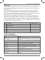
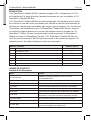
MP-Bus actuactor MP-Bus address
1 VAV damper, exhaust 1
2 VAV damper, inlet 2
3 VAV damper, inlet 3
4 Heating valve 4
5 Cooling valve 5
6 Combination valve (heating/cooling) 6
7 Six-ways valve 7
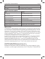
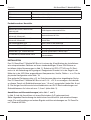
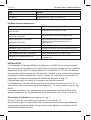
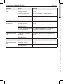
PRODUCT PROGRAMME
Products from OJ Electronics
Type Product
OJ-ZoneMaster
Master module for controlling max. 25 x OJ-ZoneModule-
MP units
OJ-ZoneModule-MP Zone module for controlling a single zone
OJ-RPT-20T Room control panel with touch screen
TTH-6202 Duct temperature transmitter with Modbus
TTH-6040-W Room temperature transmitter with Modbus
HTH-6202 Humidity and temperature transmitter with Modbus
VTH-6202
Duct VOC transmitter with Modbus (fumes from volatile
organic compounds)
OJ-Air2PWR80 Voltage supply unit, 2x24 VAC, 2x60 VA
ETT-KH Cover for OJ GreenZone™ Modules, wall mounting
ETFWP-998
PT1000 room sensor with dial for adjusting the temperature
set point

5
© 2019 OJ Electronics A/S
OJ GreenZone™ Module MP-Bus English
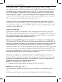
Type Product
ETF-1098L1-4 PT1000 duct sensor (°C)
ETF-998-H PT1000 room sensor (°C), 80x80 mm
Products from other suppliers
Type Product
Belimo LMV-D3-MP, NMV-D3-MP,
CMV-XXX-MP
VAV damper actuator MP-Bus
Belimo CQ24A-MPL, LR24A-MP,
NR24A-MP, SR24A-MP
Heating valve actuator MP-Bus
Belimo CQ24A-MPL, LR24A-MP,
NR24A-MP, SR24A-MP
Cooling valve and combination heating/cooling
actuator for MP-Bus
050-8-0004 eSENSE Duct CO2 sensor for duct mounting
Thermokon TFR 1,8, TFR 1,8-R Frost thermostat with 1.8 m capillary tube
Thermokon WRF06I / RDI Motion sensor for surface mounting
Telephone cable, type: TD6006 Black Telephone cable, 6-core, make: INEC
TE Connectivity telephone connector, RJ12 Modular telephone conn. 6/6, RJ12 standard conn.
INSTALLATION
OJ GreenZone™ Module MP-Bus should be fitted to a standard 35 mm DIN rail mount-
ed in an enclosure corresponding to the installation site classification (see fig. 2 for unit
dimensions). The unit itself is classed as IP20 and ETT-KH from OJ Electronics can be
used for such covering purposes. The most practical location will often be in the vicinity
of other components, valves, sensors, etc. associated with the VAV zone. An overview
of the physical configuration of the system is given in fig. 19.
An ideal location would be above a suspended ceiling panel. OJ GreenZone™ Module
MP-Bus must be provided with a 24 VAC, +/-15% power supply and is therefore
equipped with looping terminals (max. 1.5 mm
2
) for the purpose (see figs 8 and 9).
Other connections are made by means of a combination of RJ12 connectors and screw
terminals for connecting wires of max. 1.5 mm
2
cross-sectional area (see fig. 3).
Connections and indications (see overview in fig. 1)
In fig. 3, all connectors are marked with a letter (A – P).
See below for descriptions of electrical connection of the various components, inputs
and outputs, and other signals and indications of the OJ GreenZone™ Module MP-Bus.

6
© 2019 OJ Electronics A/S
Connectors "A-D" – MP-Bus actuators (see figs 3, 14, 14A, 16 & 16A)
MP-Bus actuators are connected by means of screw terminals. MP-Bus actuators and
VAV damper motors can be connected and freely distributed among the four MP-Bus
connectors. The maximum distance between OJ GreenZone™ Module MP-Bus and the
actuators is 30 m. All actuators must be put into to one of the MP-bus addresses in the
above table. All actuators must have dierent addresses. Address 4 and 5 cannot be
used together with address 6 or 7.
MP-Bus address and communication parameters are set in Belimo actuators using the
Service-Tool ZTH-EU programming unit from Belimo. Instructions for setting MP-Bus
addresses in Belimo actuators can be found at www.belimo.eu
MP-Bus VAV Dampers
OJ GreenZone™ Module MP-Bus can control three VAV dampers: one VAV damper in
the extract duct and two VAV damper in the supply duct. Supply VAV damper must have
MP-Bus address 2 and 3. Extract VAV damper must have MP-Bus address 1.
MP-Bus valve motors for heating and cooling systems
OJ GreenZone™ Module MP-Bus can control two MP-Bus valve motors: one valve mo-
tor for a heating element and one valve motor for a cooling element, both located in the
inlet duct. Alternatively it can control either a combination valve motor (heating/cooling)
or a 6 way valve motor. The heating valve must have MP-Bus address 4 and the cooling
valve must have address 5. The combination valve must have MP-bus address 6 and
the 6 way valve address 7.
Connection of temperature sensor in inlet duct (see figs 3 & 15)
It is possible to connect a sensor located in the inlet duct. The actual value recorded by
the sensor is shown on the zone's webpage. The temperature is used to control inlet
temperature.
NOTE! The sensor must be of PT1000 type.
• The sensor should be connected to terminals 30 & 31 (see fig. 15).
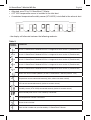
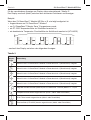
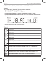
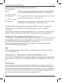
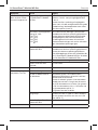
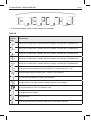
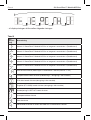
Display “G” (see figs 3 and 17)
OJ GreenZone™ Module MP-Bus is equipped with a 2-digit display (fig. 3, pos. “G”).
The display indicates various things as shown in table 3 below.
The display alternates (flashes) between the activated functions and readouts.
Example:
If the OJ GreenZone™ Module MP-Bus is configured as follows:
• Connected to OJ GreenZone™ Master 1
English OJ GreenZone™ Module MP-Bus

7
© 2019 OJ Electronics A/S
• Allocated zone 13 by OJ GreenZone™ Master
• A PT1000 temperature sensor is installed in the inlet duct
• A combined temperature/humidity sensor (HTH-6202) is installed in the exhaust duct
- the display will alternate between the following readouts:
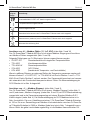
Table 3
Display
readout
Comments
Actual OJ GreenZone™ Module MP-Bus is integrated in zone section 1 (ZoneMaster1)
Actual OJ GreenZone™ Module MP-Bus is integrated in zone section 2 (ZoneMaster2)
Actual OJ GreenZone™ Module MP-Bus is integrated in zone section 3 (ZoneMaster3)
Actual OJ GreenZone™ Module MP-Bus is integrated in zone section 4 (ZoneMaster4)
Actual OJ GreenZone™ Module MP-Bus is integrated in zone section 5 (ZoneMaster5)
Shows the actual number (address) of the OJ GreenZone™ Master (interval: 1-25)
Temperature sensor connected correctly (inlet, exhaust or room sensor)
CO2 sensor connected correctly (exhaust or room sensor)
Humidity sensor (HTH-XXXX) connected correctly (exhaust or room sensor)
Room control panel OJ-RPT-20T correctly connected
Two temperature sensors connected
Sensor short-circuited
Zone section number not yet allocated by OJ GreenZone™ Master
OJ GreenZone™ Module MP-Bus English

8
© 2019 OJ Electronics A/S
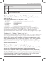
Display
readout
Comments
Zone number (address) not yet allocated by OJ GreenZone™ Master
Software update in progress
Connector “H” – Modbus sensor (°C, %rh or VOC) (see figs 3 and 18)
OJ GreenZone™ Module MP-Bus is equipped with a Modbus input for connecting
Modbus sensors (figs 3 and 18).
It is possible to connect a sensor of the following type from OJ Electronics:
• OJ-RPT-20T Room control panel with built-in temperature sensor
• TTH-6202 Duct temperature sensor
• TTH-6040-W Room temperature sensor
• VTH-6202 (VOC sensor)
• HTH-6202 (combined temperature and humidity sensor)
In larger rooms where you want to measure the temperature in several places, the
maximum number that can be mounted is 1 x OJ-RPT-20T, 1 x TTH-6040-W with the
dial in position 1, and 1 x TTH-6040-W with the dial in position 2. The Zone Module
calculates and uses the average temperature automatically from these sensors. The
terminal layout of the RJ12 connector is shown in fig. 6.
Connector “J” – “Modbus in” entry port (see figs 3 and 5)
OJ GreenZone™ Module MP-Bus is equipped with a “Modbus in” (see figs 3 and 5)
and a “Modbus out” (see figs 3 and 13) RJ12 connector for integration in the zone-
control system with a standard Modbus RJ12 cable (see fig. 4). The terminal layout of
the RJ12 Modbus connector is shown in fig. 6. The max. permissible distance between
two successive OJ GreenZone™ Module units is 100 m. The max. permissible total
cascade length of Modbus cable between all OJ GreenZone™ Module units is 2500 m.
The Modbus cable must be as shown in fig. 7. Modbus communication is OK when the
yellow LED flashes regularly.
Connector “K” – Voltage supply (see figs 8 and 9)
OJ GreenZone™ Module MP-Bus must be equipped with a 24 VAC power supply (see
figs 8 and 9). The 24 VAC connector is equipped with looping terminals to allow looping
to max. two other OJ GreenZone™ Module MP-Bus units.
The exit terminals (terminals 3 and 4) are short-circuit protected. This means that the OJ
GreenZone™ Module MP-Bus will continue to function even if the exit terminals (3 and
4) are short-circuited. It will therefore only be the subsequent OJ GreenZone™ Module
units that fail and become disconnected if terminals 3 and 4 are short-circuited.
English OJ GreenZone™ Module MP-Bus

9
© 2019 OJ Electronics A/S
The recommended cross-sectional wire area is 2x1.5 mm
2
. Modbus communication is
OK when the green LED flashes regularly.
NOTE!
The short-circuit protection means there is a limit to the load that can be placed on the exit
terminals (3 and 4). As a result, no more than two OJ GreenZone™ Module units may be
connected to exit terminals 3 and 4 (see fig. 9).
Connector “L” – PT1000 temperature sensor, humidity sensor and CO2 sensor (see
figs 3, 10 and 10A)
OJ GreenZone™ Module MP-Bus is equipped with inputs for analogue sensors (see figs
3, 10 and 10A). The inputs allow connection of a standard PT1000 sensor and a CO2
sensor with a standard 0-10 VDC output signal = 0-2000 ppm.
The sensors should be connected to the RJ12 connector marked “L” in fig. 3.
Note: This connector is NOT a Modbus connector.
Room temperature
sensor: The PT1000 room temperature sensor can be installed in the
exhaust duct or the room. It connects to screw terminal 9 and
10. (See fig. 10).
0-10 VDC input
for CO2 sensor: The CO2 sensor can be installed in the exhaust duct or in the
room. It should be connected to pins 5, 6 and 8 (see fig. 10).
0-10 VDC input
for humidity sensor: The humidity sensor can be installed in the exhaust duct or in
the room itself. It should be connected to screw terminals 6, 7
and 8 (see fig. 10A).
If no Modbus temperature sensor is connected to the connector marked “H”, the
PT1000 sensor connected to this input (“L”) will automatically be configured as an
exhaust/room sensor.
If a Modbus sensor is connected to the connector marked “H”, the Modbus sensor
values have higher priority than that of the humidity sensor on terminal 7 and the
temperature sensor on terminal 10.
Connector “M” – Temperature oset (°C) (see figs 3 and 11)
OJ GreenZone™ Module MP-Bus is equipped with an inlet for the connection of a
control unit for user-determined oset in room temperature (see figs 3 and 11). Via the
web user-interface, the temperature oset can be set to either +/-3 °C or +/-5 °C.
OJ GreenZone™ Module MP-Bus English

10
© 2019 OJ Electronics A/S
The temperature oset potentiometer ETFWP-998 from OJ Electronics has both
PT-1000 room sensor and potentiometer.
NOTE!
If an alternative potentiometer is used, the potentiometer resistance must be
min. 4.7 kΩ and max. 22 kΩ.
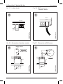
Connector “N” – Window contact, frostalarm and PIR sensor (see fig. 3)
OJ GreenZone™ Module MP-Bus is equipped with digital inputs for the connection of
window contact, frost thermostat and PIR sensor. On the overview diagram (fig. 3), the
input terminals are marked “N”.
Frost thermostat
The frost thermostat should be attached physically to the heating element. Suitable
thermostats are Danfoss type KP61, Thermokon type TFR or TFR-R, or similar ther-
mostat with bulb or capillary tube. The bulb or capillary tube should be attached to the
heating element in the air flow on the hot side of the element. If the frost thermostat is
activated (digital input opens), the installed heating valve will be forced to open 100 %.
The frost thermostat should be connected electrically as shown in fig. 12. The NC
contact of the frost thermostat should be used so that the input is active when there is
no danger of frost. The input is factory-equipped with a jumper.
Window contact
The window contact should be physically attached to the window or windows to be
monitored. If several windows are to be monitored, the window contacts should be con-
nected in series. If the windows are opened (the window contact is opened), the heating
and cooling valves will be forcibly closed. The VAV damper can be set to close.
The window contact(s) should be electrically connected as shown in fig. 20. The NO
contact of the window contact(s) should be used so that the input is active when the
window(s) is(are) closed. The input is factory-equipped with a jumper.
PIR sensor/motion detector
The PIR sensor should be positioned in the area of the room where motion is to be
detected. If several PIR sensors are to be used, they should be connected in parallel. If
the PIR sensor(s) detect motion in the room, the zone will be activated and controlled in
accordance with the set operating parameters.
The PIR sensor(s) should be electrically connected as shown in fig. 21.
The NO contact of the PIR sensor(s) should be used so that the input is active when
motion is detected in the room.
English OJ GreenZone™ Module MP-Bus

11
© 2019 OJ Electronics A/S
Connector “P” – “Modbus out” exit port (see figs 3 and 13)
OJ GreenZone™ Module MP-Bus is equipped with a “Modbus in” (see figs 3 and 5) and
a “Modbus out” (see figs 3 and 13) RJ12 connector for integration in the zone-control
system with a standard Modbus RJ12 cable (see figs 4, 5 and 13). The terminal layout
of the RJ12 Modbus connector is shown in fig. 6. The Modbus cable must be as shown
in fig. 7. Modbus communication is OK when the green LED flashes regularly.
Addressing OJ GreenZone™ Module MP-Bus
The OJ GreenZone™ Module MP-Bus is addressed automatically by the OJ Green-
Zone™ Master to which it is connected.
The address is shown on the display of the OJ GreenZone™ Module MP-Bus (see table
3 in these instructions). Further information about addressing is found in the OJ Green-
Zone™ Master manual and in OJ Green Zone installer instructions.
Safeguarding data in OJ GreenZone™ Module MP-Bus
In the event of communication faults and/or power failure to the OJ GreenZone™
Module MP-Bus, all data will be saved. When communication and/or the power sup-
ply has been re-established, the OJ GreenZone™ Module MP-Bus will automatically
resume normal operation.
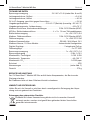
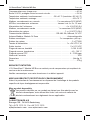
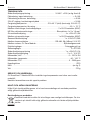
TECHNICAL DATA
Supply voltage ............................... 24 VAC ±10% (see figs 8 and 9)
Consumption, no load ............................................ < 3.4 VA
Consumption with max. load ........................................< 40 VA
24V AC output, short-circuit protected ................................< 24 VA
Ambient temperature, operation ................. -20/+40 °C (transient -30/+50 °C)
Ambient temperature, storage ....................................-50/+70 °C
Modbus, cascade connections ......................2 x RJ12 connectors (6P6C)
MP-Bus, actuator connections ....................4 x 3 x 1.5 mm
2
screw terminals
Actuator supply ..........................................4 x +24V AC 0.3A
Modbus, sensor connections .........................1 x RJ12 connector (6P6C)
Sensor supply ...........................................1 x +24V DC 0.25A
Modbus communication ..........................RS-485, 38.4 kBaud, 24 VDC
Modbus address, OJ Zone Module ............................ Self-configuring
Digital inputs .............................................2 x built-in pull-up
Sensor inputs .................................................2 x PT1000
Supply voltage ...........................................1 x +24V DC 0.1A
Voltage input . . . . . . . . . . . . . . . . . . . . . . . . . . . . . . . . . . . . . . . . . . . . . . . . 2 x 0-10 VDC
Measuring range, humidity ......................................0-100 % RH
Measuring range, temperature ...................................-40 - 100 °C
OJ GreenZone™ Module MP-Bus English

12
© 2019 OJ Electronics A/S
Measurement range CO
2
...................................... 0 - 2000 ppm
Enclosure rating .....................................................IP20
Dimensions (see fig. 2)
Weight ..........................................................270 g
SERVICE AND MAINTENANCE
OJ GreenZone™ Module MP-Bus contains no components that require service or main-
tenance. Please contact your supplier if faults arise.
DISPOSAL AND ENVIRONMENTAL PROTECTION
Help protect the environment by disposing of the packaging and redundant products in
an environmentally responsible manner.
Product disposal
Products marked with this symbol must not be disposed of together with
household refuse but must be delivered to a waste collection centre in accord-
ance with applicable local regulations.
OJ ELECTRONICS A/S
Stenager 13B · DK-6400 Sønderborg, Tel. +45 73 12 13 14 · Fax +45 73 12 13 13
[email protected] · www.ojelectronics.com
CE MARKING
2004/108/EC EMC DIRECTIVE / The European parliament and of the council of
15 December 2004 on the approximation of the laws of the Member States relating to
electromagnetic compatibility and repealing Directive 89/336/EEC.
2006/95/EC LOW VOLTAGE DIRECTIVE / Council Directive 2006/95/EC of 12
December 2006 on the harmonization of the laws of Member States relating to electrical
equipment designed for use within certain voltage limits.
2011/65/EU RoHS DIRECTIVE / Directive 2011/65/EU of the European Parliament
and of the Council of 8 June 2011 on the restriction of the use of certain hazardous
substances in electrical and electronic equipment.
Applied standards
EN 60730-1 2000 / Automatic electrical controls for household and similar use
Part 1: General requirements.
English OJ GreenZone™ Module MP-Bus

13
© 2019 OJ Electronics A/S
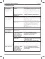
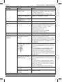
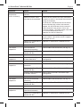
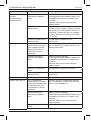
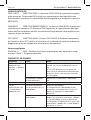
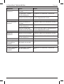
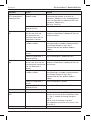
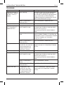
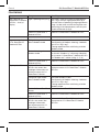
TROUBLESHOOTING
Symptom Cause Action
OJ GreenZone™
Module MP-Bus
inoperative – no light
in display
No power Check that there is 24 VAC on entry terminals
1 and 2 and exit terminals 3 and 4.
If there is no voltage on exit terminals 3 and 4,
the components supplied from these terminals
(3 and 4) have either short-circuited or are
overloaded.
Defective OJ GreenZone™
Module MP-Bus
Replace OJ GreenZone™ Module MP-Bus.
No communication
to OJ GreenZone™
Module MP-Bus
Poor or no connection in
Modbus cable
Check Modbus cable.
Configuration of Modbus cable and connector
is shown in figs 6 and 7.
Repair or replace defective Modbus cable.
Incorrect connection of
Modbus cable
Check that the Modbus communication cable
is connected to the "Modbus in" connector
and looped to the next OJ GreenZone™
Module MP-Bus from the "Modbus out"
connector.
(See figs 4, 5 and 13.)
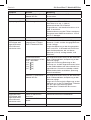
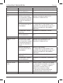
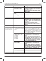
No communication
to OJ GreenZone™
Module MP-Bus
Defective OJ GreenZone™
Module MP-Bus
Replace OJ GreenZone™ Module MP-Bus.
Display shows "9" OJ GreenZone™ Module
MP-Bus has not yet
received information on
section number from OJ
GreenZone™ Master
Wait until OJ GreenZone™ Master
has allocated a section number to OJ
GreenZone™ Module MP-Bus.
Poor or no connection in
Modbus cable
Check Modbus cable.
Configuration of Modbus cable and connector
is shown in figs 6 and 7.
Repair or replace defective Modbus cable.
Defective OJ GreenZone™
Master
Replace OJ GreenZone™ Master.
Defective OJ GreenZone™
Module MP-Bus
Replace OJ GreenZone™ Module MP-Bus.
Display shows "99" OJ GreenZone™ Module
MP-Bus has not yet
received information on
zone number from OJ
GreenZone™ Master
Wait until OJ GreenZone™ Master has
allocated a zone number to OJ GreenZone™
Module MP-Bus.
OJ GreenZone™ Module MP-Bus English

14
© 2019 OJ Electronics A/S
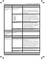
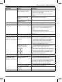
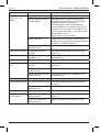
Symptom Cause Action
Poor or no connection in
Modbus cable
Check Modbus cable.
Configuration of Modbus cable and connector
is shown in figs 6 and 7.
Repair or replace defective Modbus cable.
Defective OJ GreenZone™
Master
Replace OJ GreenZone™ Master.
Defective OJ GreenZone™
Module MP-Bus
Replace OJ GreenZone™ Module MP-Bus.
Display shows "SC" Sensor short-circuited Check the connected PT1000 sensor.
The sensor should be connected to the RJ12
connector marked "L" in fig. 3 – correct
connection is shown in fig. 10.
Check sensor resistance.
The measured resistance should be
approximately 1078 Ω at 20°C.
VAV damper or
heating/cooling valve
inoperative
No voltage supply to OJ
GreenZone™ Module
MP-Bus
Check that there is 24V AC on entry terminals
1 and 2 and exit terminals 3 and 4.
If there is no voltage on exit terminals 3 and 4,
the components supplied from these terminals
(3 and 4) have either short-circuited or are
overloaded.
Actuator supply terminals
lack 24V AC:
(+18- 20)
(+21- 23)
(+24- 26)
(+27- 29)
Remove the wires connected to the terminals
and check whether there is voltage across the
terminals.
If, once the load has been removed, voltage
can be measured across the terminals, it is
highly likely that the wires connecting the
actuator are short-circuited. Remove the short
circuit and reconnect the actuator. Check the
voltage again.
Defective OJ GreenZone™
Module MP-Bus
Remove the wires connected to the terminals
and check whether there is voltage across the
terminals.
If, once the load has been removed, voltage
cannot be measured across the terminals, it is
highly likely that the OJ GreenZone™ Module
MP-Bus is defective.
Replace OJ GreenZone™ Module MP-Bus.
Fault in the electrical con-
nections
Check electrical connections.
Defective valve or VAV
actuator
Replace actuator.
English OJ GreenZone™ Module MP-Bus

15
© 2019 OJ Electronics A/S
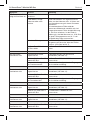
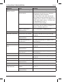
Symptom Cause Action
Sensor for inlet
temperature
shownincorrectly
Fault in the electrical con-
nections
Check electrical connections.
Defective sensor: short-
circuited or disconnected
Check sensor. Remove the wires connected
to terminals 30 & 31 and check the resistance
using an ohmmeter.
If the sensor is disconnected, the resistance
will be infinitely high, while a resistance of
approx. 0.0 ohm indicates that the sensor is
short-circuited. If the sensor is OK, a resi-
stance of approx. 1078 ohm will be measured
at a sensor temperature of 20°C.
Replace the sensor if defective.
Incorrect sensor type The sensor must be of PT1000 type, meaning
that the ohmic value of the sensor is approx.
1078 ohm at 20°C.
Defective OJ GreenZone™
Module MP-Bus
Replace OJ GreenZone™ Module MP-Bus.
Frost alarm
inoperative
Frost thermostat
connected incorrectly
Check cables and connections (see fig. 12).
Defective OJ GreenZone™
Module MP-Bus
Replace OJ GreenZone™ Module MP-Bus.
Frost alarm
inoperative
Incorrect web configuration
of frost thermostat
See installer instructions for correct input
configuration.
Window contact
inoperative
Window contact connected
incorrectly
Check cables and connections (see fig. 12).
Defective OJ GreenZone™
Module MP-Bus
Replace OJ GreenZone™ Module MP-Bus.
Incorrect web configuration
of window contact
See installer instructions for correct input
configuration.
PIR sensor
inoperative
PIR sensor connected
incorrectly
Check cables and connections (see fig. 12).
Defective OJ GreenZone™
Module MP-Bus
Replace OJ GreenZone™ Module MP-Bus.
Temperature oset
inoperative
Oset potentiometer
connected incorrectly
Check cables and connections (see fig. 11).
Defective OJ GreenZone™
Module MP-Bus
Replace OJ GreenZone™ Module MP-Bus.
OJ GreenZone™ Module MP-Bus English

© 2019 OJ Electronics A/S
16
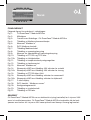
BILDUNGEN
Folgende Abbildungen finden sich ganz hinten in der Anleitung:
Abb. 1: OJ GreenZone™ Module MP-Bus
Abb. 2: Maßskizze
Abb. 3: Anschlussübersicht OJ GreenZone™ Module MP-Bus
Abb. 4: Anschluss der Modbus-Kommunikation
Abb. 5: „Modbus-Eingang“-Terminal
Abb. 6: Modbus RJ12-Stecker
Abb. 7: Modbuskabel Anschlüsse
Abb. 8: Anschluss Spannungsversorgung
Abb. 9: Schleifenklemmen für Spannungsversorgung
Abb. 10: Anschluss PT-1000- und CO2-Fühler
Abb. 10A: Anschluss des Feuchtefühlers
Abb. 11: Anschluss Temperaturschieber
Abb. 12: Anschluss des Frostthermostats
Abb. 13: „Modbus-Ausgang“-Terminal
Abb. 14: Beispiel für MP-Bus-Anschluss: Abluft-VVS-Stellantrieb
Abb. 14A: Beispiel für MP-Bus-Anschluss: Zuluft-VVS-Stellantrieb
Abb. 15: Anschluss des PT-1000-Fühlers, Zuluft
Abb. 16: Beispiel für MP-Bus-Anschluss: Heizventil-motor
Abb. 16A: Beispiel für MP-Bus-Anschluss: Kühlventil-motor
Abb. 17: 2-stelliges Display
Abb. 18: „Modbus-Fühler“ RJ12-Stecker
Abb. 19: Konfigurationsübersicht
Abb. 20: Anschluss Fensterkontakt
Abb. 21: Anschluss PIR-Melder
ALLGEMEINES
Das OJ GreenZone™ Module MP-Bus ist eine elektronische Steuerung (Regler) für VVS-
Zonen in Lüftungsanlagen. Das OJ GreenZone™ Module MP-Bus umfasst alle die Funkti-
onen, die zur energie- und komfortoptimalen Steuerung einer VVS-Zone erforderlich sind.
Deutsch

17
© 2019 OJ Electronics A/S© 2019 OJ Electronics A/S
BILDUNGEN
Folgende Abbildungen finden sich ganz hinten in der Anleitung:
Abb. 1: OJ GreenZone™ Module MP-Bus
Abb. 2: Maßskizze
Abb. 3: Anschlussübersicht OJ GreenZone™ Module MP-Bus
Abb. 4: Anschluss der Modbus-Kommunikation
Abb. 5: „Modbus-Eingang“-Terminal
Abb. 6: Modbus RJ12-Stecker
Abb. 7: Modbuskabel Anschlüsse
Abb. 8: Anschluss Spannungsversorgung
Abb. 9: Schleifenklemmen für Spannungsversorgung
Abb. 10: Anschluss PT-1000- und CO2-Fühler
Abb. 10A: Anschluss des Feuchtefühlers
Abb. 11: Anschluss Temperaturschieber
Abb. 12: Anschluss des Frostthermostats
Abb. 13: „Modbus-Ausgang“-Terminal
Abb. 14: Beispiel für MP-Bus-Anschluss: Abluft-VVS-Stellantrieb
Abb. 14A: Beispiel für MP-Bus-Anschluss: Zuluft-VVS-Stellantrieb
Abb. 15: Anschluss des PT-1000-Fühlers, Zuluft
Abb. 16: Beispiel für MP-Bus-Anschluss: Heizventil-motor
Abb. 16A: Beispiel für MP-Bus-Anschluss: Kühlventil-motor
Abb. 17: 2-stelliges Display
Abb. 18: „Modbus-Fühler“ RJ12-Stecker
Abb. 19: Konfigurationsübersicht
Abb. 20: Anschluss Fensterkontakt
Abb. 21: Anschluss PIR-Melder
ALLGEMEINES
Das OJ GreenZone™ Module MP-Bus ist eine elektronische Steuerung (Regler) für VVS-
Zonen in Lüftungsanlagen. Das OJ GreenZone™ Module MP-Bus umfasst alle die Funkti-
onen, die zur energie- und komfortoptimalen Steuerung einer VVS-Zone erforderlich sind.
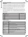
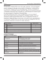
BESCHREIBUNG
Das OJ GreenZone™ Module MP-Bus steuert VVS-Klappen, Temperatur, CO2 und Luft-
feuchtigkeit im Raum, abhängig davon, welche Fühler an die Einheit angeschlossen sind.
Das OJ GreenZone™ Module MP-Bus ist selbst konfigurierend. Dazu führt die Steue-
rung einen Test der angeschlossenen Einheiten durch und regelt nach Abschluss der
Installation und Aktivierung des OJ GreenZone™ Module MP-Bus auf Basis der ange-
schlossenen Komponenten, Fühler, Stellantriebe u. a. m. die Zone optimal.
Einstellungen und Bedienung erfolgt über den integrierten Webserver; der Zugri auf
den Webserver erfolgt über den angeschlossenen OJ GreenZone™ Master.
An jeden OJ GreenZone™ Master können max. 25 Stk. OJ GreenZone™ Modules an-
geschlossen werden. OJ GreenZone™. Modul MP-Bus ist mit vier MP-Bus anschlüsse
für Ventil- und Klappenmotoren ausgestattet. Die Motoren können frei zwischen den
Anschlüssen verteilt werden.
MP-Bus aktuator MP-Bus Adresse
1 VVS-Klappe, Abluft 1
2 VVS-Klappe, Zuluft 2
3 VVS-Klappe, Zuluft 3
4 Heizungsventil 4
5 Kühlventil 5
6 Kombiventil (Heizen/Kühlen) 6
7 6-Wege Ventil 7
PRODUKTPROGRAMM
Produkte von OJ Electronics
Typ Produkt
OJ-ZoneMaster Master-Modul zur Steuerung von max. 25 Stk. OJ-ZoneModule-MP
OJ-ZoneModule-MP Zonenmodul zur Steuerung einer Zone
OJ-RPT-20T Raumbedienfeld mit Touchscreen
TTH-6202 Kanaltemperatur-Messumformer mit Modbus
TTH-6040-W Raumtemperatur-Messumformer mit Modbus
HTH-6202 Kanal-Feuchtigkeits- und Temperaturmessumformer mit Modbus
VTH-6202 Kanal-VOC-Messumformer mit Modbus (Schadstokonzentration)
OJ-Air2PWR80 Spannungsversorgung 2 × 24 V~, 2 × 60 VA
ETT-KH Abdeckung für OJ GreenZone™ Module, Wandmontage
ETFWP-998
PT-1000-Raumfühler mit Rad zur Einstellung
des Temperatur-Sollwerts
OJ GreenZone™ Module MP-Bus Deutsch

18
© 2019 OJ Electronics A/S
Typ Produkt
ETF-1098L1-4 PT-1000-Kanalfühler (°C)
ETF-998-H PT-1000 Raumfühler (°C), 80 × 80 mm
Produkte anderer Hersteller
Typ Produkt
Belimo LMV-D3-MP, NMV-D3-MP,
CMV-XXX-MP
VVS-Klappenstellantrieb MP-Bus
Belimo CQ24A-MPL, LR24A-MP,
NR24A-MP, SR24A-MP
Heizventilmotor MP-Bus
Belimo CQ24A-MPL, LR24A-MP,
NR24A-MP, SR24A-MP
Kühlventil und kombinierter Heiz-/Kühlventilmotor
für MP-Bus
050-8-0004 eSENSE Duct CO2-Fühler für Kanalmontage
Thermokon TFR 1,8, TFR 1,8-R Frostthermostat mit 1,8 m Kapillarrohr
Thermokon WRF06I / RDI Bewegungsmelder für Aufputzmontage
Telefonkabel, Typ: TD6006 Schwarz 6-Leiter-Telefonkabel, Fabrikat INEC
TE Connectivity Telefonstecker, RJ12
Modular Telefon-Anschluss 6/6, RJ12-Standard-
steckverbinder.
INSTALLATION
Das OJ GreenZone™ Module MP-Bus ist in einem der Klassifikation des Installations-
orts entsprechendem Gehäuse auf einer standardmäßigen 35 mm DIN-Schiene zu
installieren (siehe Abmessungen in Abb. 2). Schutzart ist IP20; ETT-KH von OJ Elect-
ronics ist als Abdeckung dafür geeignet. Geeignetster Standort ist in der Regel in der
Nähe der in der VVS-Zone angeschlossen Komponenten, Ventile, Fühler u. a. m. Für die
physische Konfiguration siehe Abb. 19.
Eine optimale Platzierung wäre z. B. im Zwischenraum über einer abgehängten Decke.
Das OJ GreenZone™ Module MP-Bus ist mit 24 V~ ±15% zu versorgen, und deshalb
zu diesem Zweck mit Schleifenklemmen (max. 1,5 mm²) ausgestattet (siehe Abb. 8 und
9). Die übrigen Anschlüsse sind eine Kombination von RJ12-Steckverbindungen und
Schraubklemmen für Leiter mit max. 1,5mm² (siehe Abb. 3).
Anschlüsse und Kennzeichnungen (siehe Abb. 1 und 3)
In Abb. 3 sind alle Anschlüsse mit einem Buchstaben (A-P) gekennzeichnet.
Siehe folgenden Beschreibung der elektrischen Anschlüsse für jede einzelne Kompo-
nente, Ein-und Ausgänge und andere Signale und Kennzeichnungen am OJ GreenZo-
ne™ Module MP-Bus.
Deutsch OJ GreenZone™ Module MP-Bus

19
Anschlüsse „A-D“ – MP-Bus-Stellantriebe (siehe Abb. 3, 14, 14A, 16 und 16A)
MP-Bus-Stellantriebe sind über Schraubklemmen angeschlossen. MP-Bus-Stellantriebe
und VVS-Klappenmotoren können beliebig auf die vier MP-Bus-Anschlüsse verteilt
angeschlossen werden. Der Abstand zwischen OJ GreenZone™ Module MP-Bus und
den Stellantrieben darf maximal 30 m betragen. Alle Stellantriebe müssen auf eine der
in der obigen Tabelle aufgeführten MP-Bus-Adresse eingestellt sein. Jeder Stellantrieb
muss eine andere Adresse haben. Die Adressen 4 und 5 können nicht zusammen mit
den Adressen 6 und 7 verwendet werden.
Die Einstellung von MP-Bus-Adresse und Kommunikationsparameter in Belimo-
Stellantrieben erfolgt mit dem Servicetool ZTH-EU-Programmiergerät von Belimo. Eine
Anleitung zur Einstellung der MP-Bus-Adresse in Belimo-Stellgliedern findet sich auf
www.belimo.eu.
MP-Bus VVS-Klappen
OJ GreenZone™ Module MP-Bus kann drei VVS-Klappen steuern: eine VVS-Klappe
im Abluftkanal und zwei VVS-Klappen im Zuluftkanal. Die Zuluft-VVS-Klappe muss die
MP-Bus-Adresse 2 und 3 haben. Die Abluft-VVS-Klappe muss die MP-Bus-Adresse
1haben.
MP-Bus-Ventilmotoren für Heiz- und Kühlanlagen
OJ GreenZone™ Module MP-Bus kann zwei MP-Bus-Ventilmotoren steuern: einen
Ventilmotor für ein Heizelement und einen Ventilmotor für ein Kühlelement, beide im
Zuluftkanal platziert. Alternativ kann er auch entweder einen Kombiventilmotor
(Heizen/Kühlen) oder einen 6-Wege-Ventilmotor steuern. Das Heizventil muss die
MP-Bus-Adresse 4, das Kühlventil die Adresse 5 haben. Das Kombiventil muss
die MP-Bus-Adresse 6, das 6-Wege-Ventil die Adresse 7 haben.
Anschluss Temperaturfühler für Zuluft (siehe Abb. 3 und 15)
Der Anschluss eines Fühlers im Zuluftkanal ist möglich. Der aktuelle Fühlerwert wird auf
der Website der Zone angezeigt. Die Temperaturmessung wird zur Regelung der Zuluft-
temperatur benutzt.
BITTE BEACHTEN! Als Fühler ist Typ PT-1000 anzuwenden.
• Der Fühler ist an den Klemmen 30 u. 31 anzuschließen (siehe Abb. 15)
Display „G“ (siehe Abb. 3 und 17)
Das OJ GreenZone™ Module MP-Bus ist mit einem 2-stelligen Display ausgestattet
(Abb. 3, Pkt. „G“)
OJ GreenZone™ Module MP-Bus Deutsch
© 2019 OJ Electronics A/S

20
© 2019 OJ Electronics A/S
Für die verschiedenen Anzeigen am Display siehe untenstehende „Tabelle 3“.
Das Display wechselt (blinkt) zwischen den aktivierten Funktionen und Anzeigen.
Beispiel:
Wenn das OJ GreenZone™ Module MP-Bus z. B. wie folgt konfiguriert ist:
• Angeschlossen an OJ GreenZone™ Master 1
• am OJ GreenZone™ Master Zone 13 zugewiesen wurde
• ein PT-1000-Temperaturfühler im Zuluftkanal montiert ist
• ein kombinierter Temperatur-/Feuchtefühler im Abluftkanal montiert ist (HTH-6202)
- wechselt das Display zwischen den folgenden Anzeigen:
Tabelle 3
Dis-
playan-
zeige
Anmerkung
Aktuell ist das OJ GreenZone™ Module in Zonenabschnitt 1 (ZoneMaster1) integriert
Aktuell ist das OJ GreenZone™ Module in Zonenabschnitt 2 (ZoneMaster2) integriert
Aktuell ist das OJ GreenZone™ Module in Zonenabschnitt 3 (ZoneMaster3) integriert
Aktuell ist das OJ GreenZone™ Module in Zonenabschnitt 4 (ZoneMaster4) integriert
Aktuell ist das OJ GreenZone™ Module in Zonenabschnitt 5 (ZoneMaster5) integriert
Zeigt die aktuelle Nummer (Adresse) am OJ GreenZone™ Master (Bereich: 1 - 25) an
Temperaturfühler korrekt angeschlossen (Zuluft-, Abluft- oder Raumfühler)
CO2-Fühler korrekt angeschlossen (Abluft- oder Raumfühler)
Feuchtefühler (HTH-XXXX) korrekt angeschlossen (Abluft- oder Raumfühler)
Deutsch OJ GreenZone™ Module MP-Bus
Sidan laddas...
Sidan laddas...
Sidan laddas...
Sidan laddas...
Sidan laddas...
Sidan laddas...
Sidan laddas...
Sidan laddas...
Sidan laddas...
Sidan laddas...
Sidan laddas...
Sidan laddas...
Sidan laddas...
Sidan laddas...
Sidan laddas...
Sidan laddas...
Sidan laddas...
Sidan laddas...
Sidan laddas...
Sidan laddas...
Sidan laddas...
Sidan laddas...
Sidan laddas...
Sidan laddas...
Sidan laddas...
Sidan laddas...
Sidan laddas...
Sidan laddas...
Sidan laddas...
Sidan laddas...
Sidan laddas...
Sidan laddas...
Sidan laddas...
Sidan laddas...
Sidan laddas...
Sidan laddas...
Sidan laddas...
Sidan laddas...
Sidan laddas...
Sidan laddas...
Sidan laddas...
Sidan laddas...
Sidan laddas...
Sidan laddas...
Sidan laddas...
Sidan laddas...
Sidan laddas...
Sidan laddas...
Sidan laddas...
Sidan laddas...
Sidan laddas...
Sidan laddas...
Sidan laddas...
Sidan laddas...
Sidan laddas...
Sidan laddas...
Sidan laddas...
Sidan laddas...
Sidan laddas...
Sidan laddas...
Sidan laddas...
Sidan laddas...
Sidan laddas...
Sidan laddas...
Sidan laddas...
Sidan laddas...
Sidan laddas...
Sidan laddas...
Sidan laddas...
Sidan laddas...
Sidan laddas...
Sidan laddas...
Sidan laddas...
Sidan laddas...
Sidan laddas...
Sidan laddas...
-
 1
1
-
 2
2
-
 3
3
-
 4
4
-
 5
5
-
 6
6
-
 7
7
-
 8
8
-
 9
9
-
 10
10
-
 11
11
-
 12
12
-
 13
13
-
 14
14
-
 15
15
-
 16
16
-
 17
17
-
 18
18
-
 19
19
-
 20
20
-
 21
21
-
 22
22
-
 23
23
-
 24
24
-
 25
25
-
 26
26
-
 27
27
-
 28
28
-
 29
29
-
 30
30
-
 31
31
-
 32
32
-
 33
33
-
 34
34
-
 35
35
-
 36
36
-
 37
37
-
 38
38
-
 39
39
-
 40
40
-
 41
41
-
 42
42
-
 43
43
-
 44
44
-
 45
45
-
 46
46
-
 47
47
-
 48
48
-
 49
49
-
 50
50
-
 51
51
-
 52
52
-
 53
53
-
 54
54
-
 55
55
-
 56
56
-
 57
57
-
 58
58
-
 59
59
-
 60
60
-
 61
61
-
 62
62
-
 63
63
-
 64
64
-
 65
65
-
 66
66
-
 67
67
-
 68
68
-
 69
69
-
 70
70
-
 71
71
-
 72
72
-
 73
73
-
 74
74
-
 75
75
-
 76
76
-
 77
77
-
 78
78
-
 79
79
-
 80
80
-
 81
81
-
 82
82
-
 83
83
-
 84
84
-
 85
85
-
 86
86
-
 87
87
-
 88
88
-
 89
89
-
 90
90
-
 91
91
-
 92
92
-
 93
93
-
 94
94
-
 95
95
-
 96
96


OJ Electronics OJ-Zone-Module-MP Bruksanvisningar
- Typ
- Bruksanvisningar
på andra språk
Relaterade papper
-
OJ Electronics OJ-Zone-Module-M Bruksanvisningar
-
-
-
-
-
-
-
-
-
Andra dokument
-
AutomatikCentret TTH-6040-W Bruksanvisningar
-
EXHAUSTO CO2B sensor-AS Användarmanual
-
sauter EGQ 281 Assembly Instructions
-
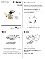 Purmo Optimizer Installationsguide
-
-
 MESCOLI LK100 Användarmanual
-
Danfoss AVTB Bruksanvisningar
-
Swegon PARASOL Zenith VAV d Bruksanvisning
-
Bosch ES1260 Användarmanual
-
OUMAN WL-BASE Deployment Manual

