
ASSA Pando display reader
Om ASSA Pando
ASSA pando display är en kombinationsläsare som stödjer både Hi-O
protokoll samt RS485 baserade protokoll.
Som standard läser pando läsaren serienummer men ASSA
rekommenderar att läsarna konfigureras för sektorläsning för att uppnå en
högre säkerhetsnivå. Välj mellan MIFARE Classic eller MIFARE DESFire.
All konfigurering av lästekniker sker med ett för anläggningen unikt
setupkort.
Hi-O installation
Hi-O enheter är enkla att installera, alla enheter ansluts parallellt med hjälp
av fyra trådar. Enheter på Hi-O bussen får vanligtvis sin matningsspänning
från DAC 530II, DAC564II eller LCU9101.
Anslut CAN-bussen till CAN-H och CAN-L samt matningen ut till CAN-
bussen på de två nästkommande plintarna i DAC/LCU, +12V & 0V.
Anslut en eller flera ASSA pando läsare samt motorlås och öppnarknappar
till CAN-bussen. Ställ SIO buss adressen till 00 i läsaren samt ställ in
funktionsval 1 för in- eller ut läsare.
Installation av pando display på SIO buss.
Anslut SIO-bussen till A och B anslutningarna samt matningen till
läsaren på +V & 0V anslutningarna (+24V & 0V).
Ställ SIO buss adressen mellan 1-99, beroende på vilken adress som finns
ledig på SIO-bussen.
Indikeringar för Hi-O Mode = SIO Adress 0
Grön: lyser när läsaren är oinitierad på Hi-O bussen, pando läsaren är inte
låst till en specifik Hi-O buss.
Röd: lyser när Pando läsaren är låst till en specifik
Hi-O buss, röd indikerar att läsaren är låst och krypterad.
Indikeringar för SIO mode adress 1-99
Grön: TX, Sänder data
Röd: RX, Tar emot data
Tabell för funktionsval via knappsats
Tangent
Funktion
1
In sida/Utsida.
ON = Insida
Off = Utsida
2
Key beep, pip vid tangenttryck samt dur &
moll signal vid ogiltigt/giltigt kort
3
Card beep, Pip för att indikera att kortet är
läst
4
Light ON, Knappsatsen ständigt belyst
5
Light Code, Knappsats belyst när
indikeringen för dörrkod/PIN kod är aktiverad
Inställningar samt adressering
Ställ ”Conf” DIP i läge ON
Tryck på ”A”
Menyn tänder upp i displayen
Växla funktionsvalen (Fx) On/Off genom att trycka på
respektive siffertangent för valen. F1 = Siffertangent 1,
osv… (Se tabell för funktioner).
Tryck därefter ”B”, till adress.
Skriv in adressen med siffertangenterna.
Hi-O = Adress 00
SIO buss Adress 1-99
Tryck ”B” för att spara
(Nu är man åter i funktionsavtals läge, ändra eller
fortsätt enligt nedan.)
Eller ställ ”Conf” DIP i läge OFF
Därefter ”B” (Läsaren startar om).
Ändra adress/Fabriksåterställning av SIO ansluten
läsare.
Ställ ”Conf” DIP i läge ON
Tryck därefter ”A”,
Tryck därefter ”B”, till adress.
För att fabriksåterställa kommunikationsnyckeln.
Behöver göras om adressen ändras eller då man bytt
databas på servern eller börjat om med en tom databas.
Se ARX manual för mer information.
o Skriv in en adress 00 (Återställer
kryptonyckel)
o Tryck ”B” för att spara (Krypto nyckel
återställd)
o Tryck därefter ”B” igen, till adress.
Skriv in adress 1-99
Ställ ”Conf” DIP i läge OFF
Tryck ”B” för att spara,
Läsaren startar om när Conf DIP är i läge OFF
Lås upp en Hi-O låst läsare.
Normalt låser man upp läsaren via den DAC eller LCU den är ansluten till, men om man
behöver låsa upp läsaren utan DAC eller den LCU den har blivit låst via, gör enligt följande.
Slå på spänningen till läsaren.
Röd LED lyser fast, som indikerar att läsaren är låst.
Slå Conf. DIP mellan ON och OFF med en sekunds intervall 6-8 gånger.
När läsaren växlar från rött till grönt är den upplåst.
Konfigurering av sektorläsning
1. Bryt och slå till spänningen till läsaren genom att ta ur den jackbara plinten och
sätta tillbaka den.
2. Grön indikering blinkar under 90 sekunder.
3. Visa setupkortet för läsaren innan den slutar blinka.
4. Läsaren indikerar med ett ”kvitter” att programmeringen är klar och den gröna
indikeringen slocknar.
5. Läsaren är nu programmerad med anläggningens krypteringsnycklar.
OBS! Om ett kort som presenteras för en ASSA Pando läsare inte har krypteringsnycklar
som överensstämmer med de i läsaren kommer den inte att visa någon indikering.
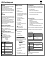
Tekniska specifikationer
Matningsspänning
12-24V DC
Strömförbrukning
12V: 65mA Max 130mA
Rekommenderad kabel
EKKX 2x2x0,2
Hi-O Kabellängd
Totalt: Max. 50 m
Grenledning: Max. 10 m
Dimensioner
H 185 mm, W 69 mm, D 22 mm.
Plint
CH
Can H
Anslutning till Hi-O buss (SIO adress = 00)
LCU9101, DAC530II eller DAC564II
CL
Can L
+V
+V (12-24V DC)
Matning läsare
0V
0V
A
RS485
Anslutning till ASSA SIO buss (RS485)
B
RS485
NC
Free
Terminering
Om läsaren sitter sist på SIO bussen ska termineringen aktiveras.
Ställ DIP 2 ”Term” i läge ON.

ASSA Pando display reader
About ASSA Pando
ASSA Pando reader is a combination reader, supports both Hi-O protocol
and RS485-based protocols.
By default reads the Pando reader serial number on the cards but ASSA
recommends that readers configured for the sector reading to achieve a
higher level of security. The programming are made with a customer specific
Setup card. Mifare classic, Desfire card and iClass is supported.
Hi-O Installation
Hi-O devices are easy to install, all devices are connected in parallel and
just using four threads. Units of Hi-O bus usually gets its supply voltage from
the DAC 530II, DAC564II or LCU9101.
Connect the CAN bus the CAN-H and CAN-L and power out to the CAN bus
at the next two terminals in the DAC/LCU, +12 V and 0V.
Connect one or more ASSA Pando readers and motor lock and RTE buttons
to the CAN bus. Set the SIO bus address to 00 in the reader and set the
function selection 1 for in or out reader.
Installing Pando display on the SIO bus.
Connect the SIO bus to the A and B terminals and power supply to the
reader to + V and 0V connections (+24 V and 0V).
Set SIO bus address from 1-99, depending on which address is available on
the SIO bus.
Indications for Hi-O mode = SIO address 0
Green: Lights when the reader is uninitialized at
the Hi-O bus, Pando reader is not locked to a specific Hi-O bus.
Red: lights when Pando reader is locked to a specific
Hi-O bus, red indicates that the reader is locked and encrypted.
Indications for SIO mode address 1-99
Green: TX, Sending data
Red: RX, Receiving data
Table for the function selection via the keypad
Key
function
1
Inside/outside reader
On = Inside
Off = Outside
2
Key beep, beep when keystrokes and major &
minor signal at invalid/valid card.
3
Card beep, Beep at card read
4
Light ON, Keypad always lit.
5
Light Code, Keypad lit when the indication for
door code/PIN code is activated
Settings and addressing
Set Conf. Dip in the ON position
Then press the “A”
The menu lights up on the display
Switching function choices (Fx) On/Off by pressing the
respective number key.
F1 = Numeric Key 1, etc .(See table for functions).
Then press the "B", to address.
Enter the address using the numeric keys.
Hi-O Address = 00
SIO bus Address 1-99
Press "B" to save
Set Conf. DIP to OFF
Restart the reader.
Change Address / Factory Reset of SIO connected
readers.
Set Conf. Dip in the ON position
Turn on the reader
Then press "B", to address.
To factory reset the communication key.
Needs to be done if the address changes or when you changed
the database on the server or starting over with an empty
database.
See ARX manual for more information.
o Enter address 00 (Restores crypto key)
o Press "B" to save (crypto key restored)
o Then press "B" again, to address.
Enter the address 1-99
Set Conf. DIP to OFF
Press the "B" to save, (Readers restart)
Unlock a locked Hi-O reader.
Normally unlocks the reader through the DAC or the LCU that is connected to, but if you
need to unlock the reader without the DAC or the LCU it has been locked by using the
following steps.
Turn on the power to the reader.
Red LED illuminates solid, indicating that the reader is locked.
Turn Conf. DIP ON and OFF at one second intervals 6-8 times.
When the reader switches from red to green is it unlocked.
Configuration of sector reading
1. Cut and connect the power to the reader, by lifting the “plug able” terminal and
putting it back.
2. Green indication flashes for 90 seconds.
3. Show the Setup card to the reader, before it stops flashing.
4. The reader indicates that the programming is finished with a “chirp” and the
green indication is unlit.
5. The reader is now programmed with the encryption keys of the site.
Note! If a card presented to an ASSA Pando display reader doesn’t have encryption keys
corresponding with the reader the reader will not indicate that anything is wrong and the
reader will not send any data.
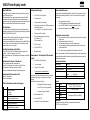
Technical specifications
Power supply
12-24V DC
Power Consumption
12V: 65 mA Max 130mA
Recommended cable
EKKX 2x2x0,2
Hi-O Cable length
Total: Max. 50 m
Branch: Max. 10 m
Dimensions
H 185 mm, W 69 mm, D 22 mm.
Terminal
CH
Can H
Connection to the Hi-O bus (DIP6 = ON)
LCU9101, DAC530II or DAC564II
CL
Can L
+V
+ V (12-24 DC)
Power to the reader.
0V
0V
A
RS485
Connecting to ASSA SIO bus (RS485)
B
RS485
NC
Free
Termination
If the reader is finally on the SIO bus, the termination shall be activated.
Set DIP 2 "Term" in the ON position.
IS559686940C
-
 1
1
-
 2
2


på andra språk
- English: Assa Abloy Pando Quick start guide
Relaterade papper
Andra dokument
-
SICK LCU-X Safety Interface Bruksanvisningar
-
FM Mattsson Cover Plate Bruksanvisningar
-
Aritech ATS1192 Bruksanvisning
-
Yale PLv03 Indoor Wi-Fi Camera Pan & Tilt Användarmanual
-
Yale 81859 Användarmanual
-
 Bewator PD30EM Installation & User Manual
-
Yale Doorman Användarmanual
-
Siemens PM500-Cotag Installationsguide
-
Yamaha CP-20 Bruksanvisning
-
Trekstor Pyrus Mini Användarguide
