GCE TERMINAL UNITS MEDIUNIT Bruksanvisningar
- Typ
- Bruksanvisningar

GCE HEALTHCARE
EN
TERMINAL UNITS MEDIUNIT
TERMINAL UNITS,INSTRUCTION FOR USE
TERMINÁLNÍ JEDNOTKY,NÁVOD K POUŽITÍ
TERMINALUNITS,BEDIENUNGSANLEITUNG
MEDISCHE AFNAMEPUNTEN,GEBRUIKSAANWIJZING
TOMA DE GASES MEDICINALES,INSTRUCCIONES DE USO
GÁZVÉTELI HELY,HASZNÁLATI UTASÍTÁS
GASUTTAG, BRUKSANVISNING
GASSUTTAK,BRUKSANVISNING
GASUDTAG,BRUGERVEJLEDNING
PÄÄTEYKSIKÖT,KÄYTTÖOHJE
TERMINALNE JEDINICE,NAPUTAK ZA UPORABU
CS
DE
NL
ES
HU
SV
NO
DA
FI
HR

2/172
EN
1. FOREWORD
GCE Terminal units (further only as ”TU”) are medical devices classi-
fi ed as Class IIb according to the Directive concerning medical devices
93/42/EEC. Conformity with essential requirements of the Directive
93/42/EEC is on the basis of the EN ISO 9170-1, EN ISO 7396-1 standards
and required national standards.
This instruction for use is valid for all other types of TU - DIN, CZ, BSI, SS.
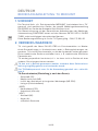
2. INTENDED USE
TU are intended to be used as outlet points at hospital low pressure gas
supply system or at medical emergency ambulances in compliance with
the EN ISO 1789 standard. TU is an outlet point where operators connect
and disconnect an inlet of other gas specifi ed medical devices, such as
medical hoses, fl owmeters,etc.
The TU are designed to be gas specifi c which means that they cannot be
connected to a medical device that is for a di erent type of gas.
TU cannot be placed into operation before these instructions are thor-
oughly read and understood.
Operator of TU must be properly trained for such operation - see chap-
ter4.
BASIC VARIANTS OF TU DIVISION ACCORDING TO THE GAS:
• Oxygen (O2)
• Medical air (AIR)
• Air for running surgical tools
(AIR-800)
• Laughing gas (nitrous oxide)
(N2O)
• Carbon dioxide (CO2)
• Underpressure (Vacuum)
(VAC)
• Nitrogen (N2)
• Argon (Ar)
• and mixtures of these gases
ENGLISH
INSTRUCTION FOR USE: TU MEDIUNIT

3/172
EN
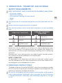
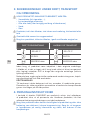
3. OPERATIONAL, TRANSPORT AND STORAGE
SAFETY REQUIREMENTS
KEEP THE PRODUCT AND ITS ASSOCIATED EQUIPMENT AWAY FROM:
• All sources of heat
• Flammable materials
• Oil or grease (including all hand creams)
• Water
• Dust.
The product and its associated equipment must be prevented from fall-
ing.
Always maintain oxygen cleanliness standards.
Use only the product and its associated equipment in a well ventilated
area.
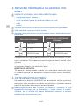
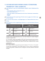
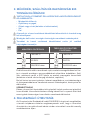
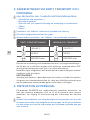
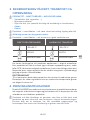
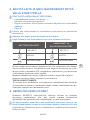
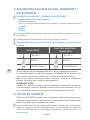
OPERATING CONDITIONS STORAGE, TRANSPORT
CONDITIONS
-20/+60 °C -30/+70 °C
10/100% 20/70%
600/1200 mbar 600/1200 mbar
Before fi rst use the product must be kept in its original packaging to en-
sure that the product is not contaminated. For transport and storage GCE
recommends use of the original packaging (including internal sealing bag
and caps).
Statutory laws, rules and regulations for medical gases, accident preven-
tion and environmental protection must be observed.
SAFETY OPERATION
TU described in this document must only be used with medical gases
and the procedures for the safe and e ective use of these medical com-
pressed gases must be followed at all times.
4. PERSONNEL INSTRUCTIONS
The Medical Devices Directive 93/42/EEC states that the product provider
must ensure that all personnel handling the product are provided with the
operating instructions & performance data.
Do not use the product without properly familiarization of the product
and its safe operation as defi ned in this Instruction for use. Ensure user
is aware of particular information and knowledge required for the gas
in use.

4/172
EN
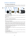
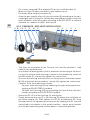
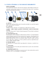
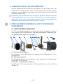
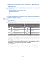
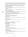
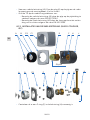
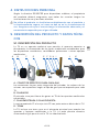
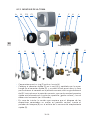
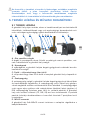
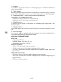
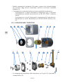
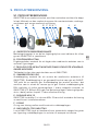
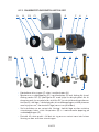
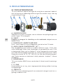
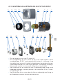
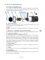
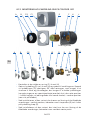
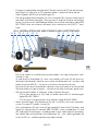
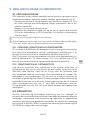
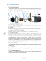
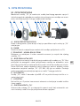
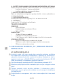
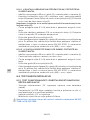
5. PRODUCT DESCRIPTION
5.1. PRODUCT DESCRIPTION
TU is a medical device to allow an operator to connect or disconnect the
supply of the required medical gas for anaesthetic devices, breathing ven-
tilators and other medical devices.
A B C D E F G H I J K
A GAS SPECIFIC PLUG
Plugs are part of the button designed in colours specifi ed to the gas for
which TU is designed for.
B BUTTON
Button serves for disconnection of the medical device connected in the
TU.
C COVER RECESSED OR EXPOSED
Recessed cover or exposed cover are basic external part of the complete
TU.
D QUICK COUPLER QC
Quick coupler is used to connect the medical devices into the TU. Quick
coupler allows only the gas specifi ed device for which also the TU is de-
signed for. Quick coupler can be only connected into the housing which
is designed for the same type of gas. Only quick coupler DIN includes so-
called parking position, other national variants of TU (CZ, BSI, SS) do not
include the parking position. Parking position is described in details below
in chapter 7 of this instruction for use.
E SCREWS M5X12
TU includes 3 pcs of screws M5x12 to be used for fi xing the housing in the
installation box.
F ORING
Housing included an o-ring as a basic sealing element between housing
and quick coupler.
G CHECK VALVE OF TU
Included in every TU is a check valve that automatically closes the housing
if nothing is connected to the quick coupler.

5/172
EN
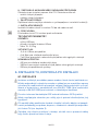
H HOUSING WITH AXIAL OR RADIAL INLET
Housing is an in-built part of installation with two general variants:
• Housing with radial inlet connection
• Housing with axial inlet connection
I LOCKING PLATE
Locking plate secures the housing with quick coupler in the installation
box.
J INSTALLATION BOX
Installation box is used for installation of TU in or on the wall.
K PLUG
The plug prevents contamination of the installation box.
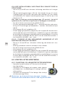
TECHNICAL PARAMETERS
DIMENSIONS:
• Height: 62,5 mm
• Diameter of installation box: 60 mm
• Weight : 0,37 kg
INLET PRESSURE:
• -0,4 to -0,9 bar for vacuum
• 4 to 5 bar for compressed medical gases
• 7 to 10 bar for air or nitrogen to be used for running the surgical tools
NOMINAL FLOW:
• 40 l/min for compressed medical gases
• 350 l/min for air or nitrogen to be used for running the surgical tools
• 25 l/min for vacuum systems
6. INSTALLATION OF TU, CHECK AFTER
INSTALLATION
6.1. INSTALLATION
Installation can only be done by a person that has the appropriate certifi -
cates according to the required national standards and laws for mounting
and repairs of concerned gas medical devices. Standards valid for such
installations and testing are ENISO7396-1 for medical central gas sys-
tems and ENISO5359 for installations with low pressure hoses.
For more information contact GCE or distributor of GCE products.
Do not connect the housing to pipeline with di erent type of gas.
During mounting use always appropriate and functional tools and keep
all safety requirements for operation, transport, storage (see chapter 3).
Ensure that all devices, equipment and also hands and work wear are
kept clean and free from oil and grease.

6/172
EN
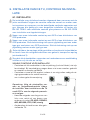
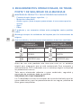
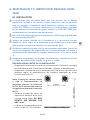
VISUAL CHECK BEFORE INSTALLATION
• Check that all components in the package (including labels) are not
damaged. If they are damaged, withdraw them from service and label.
• Visually check if the product is clean, if needed follow the procedure for
cleaning that is described in this instruction for use.
Note: Follow the local standards and project documentation during the
installation. For installation of TU GCE recommends to keep the follow-
ing procedure:
• Keep order of gases from left to right or from top to bottom as follows:
O2; N2O; O2/N2O; AIR; AIR-800; CO2; VAC; others
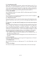
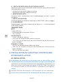
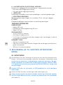
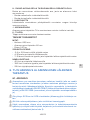
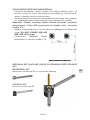
• Recommended distance between
every installed TU:
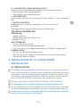
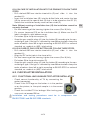
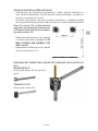
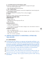
SPECIAL TOOL SET MP_00345 REQUIRED FOR QUICK COUPLER IN
STALLATION
SPANNER:
Used for keeping the QC in position
PIPE WRENCH:
Used for tightening the QC

7/172
EN
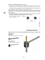
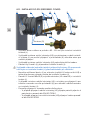
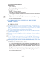
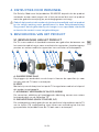
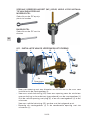
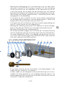
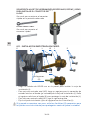
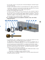
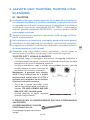
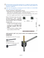
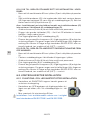
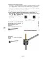
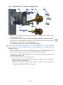
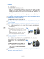
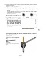
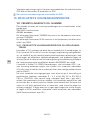
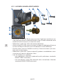
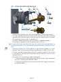
6.1.1. RECESSED COVER INSTALLATION
J L H1 I E
H2
K
4x Holes (O)
• Drill a hole of diameter 60 - 65 mm into the wall for installation of the
installation box (J).
• For axial housing (H2): drill a hole for axial inlet connection into the bot-
tom (marked) of the installation box (J). Seal the radial hole with plug (K)
to protect installation box (J).
For radial housing (H1): continue by the next point.
• Fix the installation box (J) in the prepared hole with four screws (L).
If TU is being fi xed in the wall by plastering, seal the four holes (O) need-
ed for fi xation of the cover by insulating tape to protect them against
clogging during plastering.
• Place housing (H1 or H2) in the installation box (J) together with the lock-
ing plate (I) as shown on the picture and fi x with three screws M5x12 (E).
• For radial housing (H1): Push the plug (K) on the pipe to seal the radial
hole on the installation box (J).
• Connect TU to the medical gas supply:
• Connect radial housing (H1) by soldering the pipe to the pipeline ac-
cording to EN ISO 7396-1 standard.
• Connect axial housing (H2) by connecting the hose to the axial con-
nection according to EN ISO 5359 standard.

8/172
EN
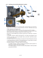
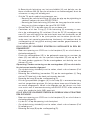
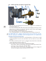
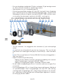
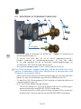
6.1.2. EXPOSED COVER INSTALLATION
J I H1 E L
H2
K
L
E
H
I
• For axial housing (H2): drill a hole for axial inlet connection into the bot-
tom (marked) of the installation box (J) and into the wall. Seal the radial
hole with plug (K) to protect installation box (J).
• For radial housing (H1): continue by the next point.
• Place housing (H1 or H2) in the installation box (J) together with the lock-
ing plate (I) as shown on the picture and fi x with three screws M5x12 (E).
• Fix completed set with two screws (L). Holes for screws are marked in
the installation box (J).
• For radial housing (H1): Push the plug (K) on the pipe to seal the radial
hole on the installation box (J).
• Connect TU to the medical gas supply:
• Connect radial housing (H1) by soldering the pipe to the pipeline ac-
cording to EN ISO 7396-1 standard.
• Connect axial housing (H2) by connecting the hose to the axial con-
nection according to EN ISO 5359 standard.

9/172
EN
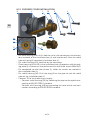
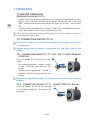
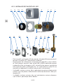
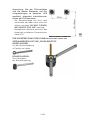
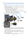
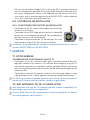
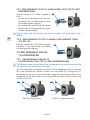
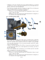
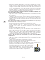
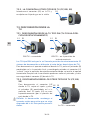
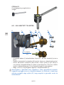
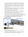
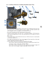
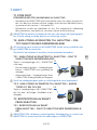
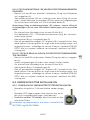
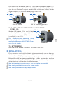
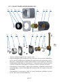
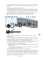
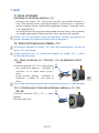
6.1.3. QUICK COUPLER INSTALLATION QC
A B C2 C1 D F H J
Guide surface
• Check presence of o-ring (F) in the housing (H).
• Fit a quick coupler (D) into the housing (H) and tighten manually. Then
tighten the QC (D) of additional 45° using the pipe wrench for tightening
and spanner for keeping the QC (see the special tools info above) in
the correct position - means quick coupler must be positioned by guide
surface down, in horizontal position (as shown on the picture).
• In case of the installation of version where locking of the connected
devices in vertical position is required, insert the locking pin (R) into the
hole in the body of QC (D).
• In case of the installation of version where locking is not required, con-
tinue by the next point.
ABC2 PJ2 R DEH
I

10/172
EN
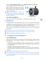
• Fix a cover (recessed C2 or exposed C1) on the installation box (J).
Make sure the CE label is located in right bottom corner.
• Fix button (B) to the quick coupler (D).
• Snap the gas specifi c plugs (A) into the button (B) according to the con-
nected gas type. If the gas is indicated by two di erent colours keep the
order of colours from left to right according to EN ISO 9170-1 or national
standard, ex. medical air (AIR) - black-white.
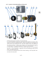
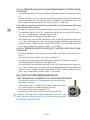
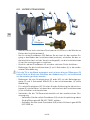
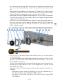
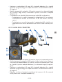
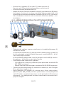
6.1.4. PENDANTS BED HEAD INSTALLATION
ABC2 Q D E I HJ2 OP L
N
• Two ways of installation of the Terminal Unit into the pendants - bed
head (L) can be performed:
a) by means of locking plate (I) that is placed on the housing of the termi-
nal unit (H) and the ready housing is placed in the pendant by means of
the M5 screws (E) - do not fully tighten the screws now.
b) secure the housing of the terminal unit (H) by means of the two screws
M4 (N) to the back of the pendant - do not fully tighten the screws now.
• Connect TU to the medical gas supply:
• Connect radial housing (H1) by soldering the pipe to the pipeline ac-
cording to EN ISO 7396-1 standard.
• Connect axial housing (H2) by connecting the hose to the axial con-
nection according to EN ISO 5359 standard.
• Screw the QC (D) into the housing (H) and tighten.
• Check presence of o-ring (F) in the housing (H) before the installation of
the Quick coupler (D). Then tighten the QC (D) of additional 45° using
the pipe wrench for tightening and spanner for keeping the QC (see the
special tools info above) in the correct position - means quick coupler
must be positioned by guide surface down, in horizontal position.

11/172
EN
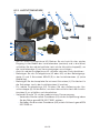
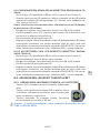
6.1.4.1 IN CASE OF INSTALLATION INTO THE PENDANT FOLLOW THESE
STEPS:
• Drill a hole of Ø65 mm into the sheet of tin (O) and slide it into the
pendant (L).
• Insert the installation box (J2) into the drilled hole and centre the box
(J2) by means of the special tool (Q) that is to be placed on the QC (D).
Secure the installation box by means of four studs (P).
Note: Without centring of installation box (J2) the installation cannot be
correctly fi nalized.
• For fi nal securing of the housing, tighten the screws (E or N) fully.
• Fix a cover (recessed C2) on the installation box (J). Make sure the CE
label is located in right bottom corner.
• Fix button (B) to the quick coupler (D).
• Snap the gas specifi c plugs (A) into the button (B) according to the con-
nected gas type. If the gas is indicated by two di erent colours keep the
order of colours from left to right according to EN ISO 9170-1 or national
standard, ex. medical air (AIR) - black-white.
6.1.4.2 IN CASE OF ONLY GCE BUTTON USE, FOLLOW THESE STEPS:
• Drill a hole of Ø65 mm into the sheet of tin (O) and slide it into the
pendant (L).
• Align the QC to the hole in the sheet of tin.
• For fi nal securing of the housing, tighten the screws (E or N) fully.
• Fix button (B) to the quick coupler (D).
• Snap the gas specifi c plugs (A) into the button (B) according to the con-
nected gas type. If the gas is indicated by two di erent colours keep the
order of colours from left to right according to EN ISO 9170-1 or national
standard, ex. medical air (AIR) - black-white.
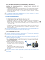
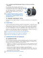
6.2. CHECKS AFTER INSTALLATION
6.2.1. FUNCTIONAL AND LEAKAGE TEST AFTER INSTALLATION
• Check correct functionality of TU by connecting the
probe (connector).
• Check if the GCE logo on the button is in the position
as on the picture, ie. the quick coupler is in the correct
position.
• Check the installed TU for leakage. Max. testing pres-
sure must not exceed 24 bar.
Installation and testing procedures must be in compliance with
EN ISO 7396-1 and EN ISO 5359 standards.

12/172
EN
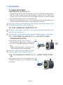
7. OPERATION
7.1. BEFORE OPERATION
PREPARATION FOR USE OF TU
• Check if the TU (including label) does not show any visible external dam-
age. If there are signs of external damage, ensure the unit is not and
label. Contact the responsible personnel and call service - see chapter
9.2.
• Check visually if the product is clean, if cleaning is needed follow proce-
dures described further in this instruction for use.
TU can be used only for the gas specifi ed on the button. Never try to use
it for di erent type of gas.
7.2. CONNECTING DEVICE TO TU
Any devices used with TU must be compatible with the gas for which TU
is intended for.
Always make sure the device is connected fi rst and then used on the
patient.
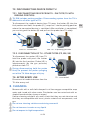
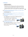
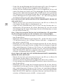
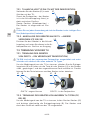
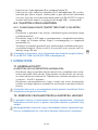
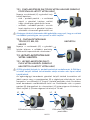
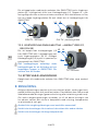
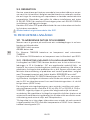
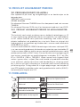
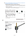
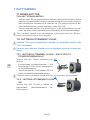
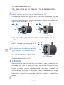
7.2.1. CONNECTING DEVICE TO TU DIN TYPE TU WITH PARKING
POSITION
Push the probe (L1) into the TU in two
steps:
• fi rst parking position - probe is fi xed
in the TU without gas fl ow on the
outlet,
• second working position - probe is
locked in the TU with gas fl ow on the
outlet.
Before each application make sure the probe is pushed into the working
position!
7.2.2. CONNECTING DEVICE TO TU OTHER TYPES CZ, BSI, SS
Push the probe (L2) into the TU and lock
it in the working position. Gas fl ow is on
the outlet.
L1
L2

13/172
EN
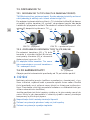
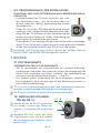
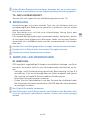
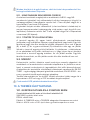
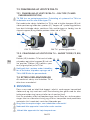
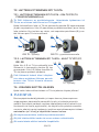
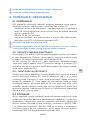
7.3. DISCONNECTING DEVICE FROM TU
7.3.1. DISCONNECTING DEVICE FROM TU DIN TYPE TU WITH
PARKING POSITION
TU DIN includes parking position. Disconnecting system from the TU is
di erent to all other types of TU.
To disconnect the medical device from TU press the button (B) into the
fi nal position and hold, the probe (L1) “jumps out” into the parking position
where the connected device is ventilated. After ventilation is completed,
you can let go of the button (B) and pull out the probe from TU safely.
DIN TU - connected DIN TU - in parking position
L1 B L1 B
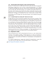
7.3.2. DISCONNECTION OF TU OTHER TYPES CZ, BSI, SS
To disconnect the probe (L2) from TU
hold the probe and press the button
(B) into the fi nal position. Probe (L2) is
spontaneously (by the gas pressure)
pulled out from TU.
During disconnecting hold the probe
fi rmly to prevent the probe springing
out of the TU. Note danger of injury.
7.4. AFTER EVERY USE
Disconnect all medical devices from the
TU after every use!
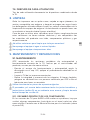
8. CLEANING
Remove dirt with a soft cloth damped in oil free oxygen compatible soap
water and rinsed with clean water. Disinfection can be carried out with an
alcohol-based solution (spray or wipes).
If other cleaning solutions are used, check that they are not abrasive and
that they are compatible with brass, plastic materials of components, and
gas.
Do not use cleaning solutions containing ammonia!
Do not immerse in water or any liquid.
Do not expose to high temperature.
L2 B
TU - connected

14/172
EN
9. MAINTENANCE AND REPAIR
9.1. MAINTENANCE
Periodical checks recommended by GCE should be done at least annually
by the provider of the product. This should include leakage and functional
tests of TU.
• Proceed with functional and leakage tests as described in chapter 6.2.
If any leakage or damage is found, use procedure described in chapter
9.2.
• Clean TU from possible contamination.
• Check the presence and status of the labels. In case of bad legibility,
contact GCE or distributor of GCE products.
Use only original spare parts.
All sealing and o-rings must be stored by provider or operator in a dry,
dark and clean storage during the complete lifetime.
9.1.1. PERIODICAL EXCHANGE OF COMPONENTS
TU variants for Air800 or N2 intended for use of running the surgical tools
must have some components (o-ring in quick coupler) exchanged every
three years. Please contact service for exchange (chapter 9.2).
All TU variants (including the above mentioned) must have some compo-
nents (quick coupler, check valve of TU, spring, o-rings in housing of TU
exchanged every ten years. Please contact service for exchange (chapter
9.2).
9.1.2. SEAL TYPE IDENTIFICATION
By servicing, repairing or replacing of internal components of the terminal
unit (H), it is easy to identify whether it is a version with internal O-ring seal
or a version with metal-to-metal seal. After removing the button (B), cover
(C) and quick coupling (D), a set of markings is visible on front surface of
terminal unit. In addition to the gas type, the batch number and the data
code, there is an indication which type of seal is used inside. Marking „S“
(as Soft) means O-ring seal, marking „M“ (as Metal) means metal-to-metal
seal.
9.2. REPAIR
Service, repair and spare parts exchange can only be done by a person
that has the appropriate certifi cates according to the required national
standards and laws for mounting and repairs of concerned gas medical de-
vices. Standards valid for such installations and testing are ENISO7396-1
for me-dical central gas systems and ENISO5359 for installations with low
pressure hoses.
For more information and actual list of spare parts contact GCE or distribu-
tor of GCE products.
Use only GCE original spare parts.

15/172
EN
10. PRODUCT LIFETIME
10.1. BATCH NUMBER AND PRODUCTION DATE
Number perforated on the housing and quick-coupler is combination of
the following data:
XXXXXXX: batch number
YY/MM: date code
Ex.: Number 7366506 indicates a component with batch number 7366506.
Ex. Number 13/04 indicates a component with manufacturing date - April,
year 2013.
10.1.1. PRODUCT LIFETIME AND WASTE MANAGEMENT
Lifetime of TU, excluding parts permanently connected to the pipeline, is
10 years. The housing part of TU, if the regular maintenance is observed
- see chapter 9, has identical length of lifetime as the hospital pipeline. At
the end of the product’s life time, the product must be withdrawn from ser-
vice. The owner of the device shall prevent the reuse of the product and
handle the product in compliance with “Directive of European Parliament
and Council 2008/98/EC on waste“.
In accordance to Article 33 of REACH GCE, s.r.o. as responsible manu-
facturer shall inform all customers if materials containing 0.1% or more of
substances included in the list of Substance of Very High Concern (SVHC).
The most commonly used brass alloys used for bodies and other brass
components contain 2-3% of lead (Pb), EC no. 231-100-4, CAS no. 7439-
92-1. The lead will not be released to the gas or surrounding environment
during normal use. After end of life the product shall be scrapped by an
authorized metal recycler to ensure e cient material handling with mini-
mal impact to environment and health.
To date we have no information that indicates that other materials con-
taining SVHC of concentrations exceeding 0.1% are included in any GCE
product.

16/172
EN
MANUFACTURER:
GCE, s.r.o. Tel : +420 569 661 111
Zizkova 381 Fax : +420 569 661 602
583 01 Chotebor http://www.gcegroup.com
Czech Republic © GCE, s.r.o.
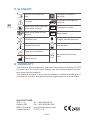
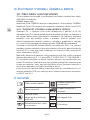
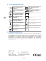
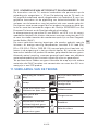
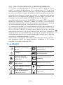
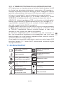
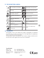
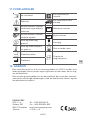
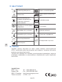
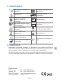
11. GLOSSARY
Consult instruction for
use
Suitable for Hospital
care use
Caution Suitable for Emergency
care use
Keep away from heat and
fl ammable material REF Catalogue number
Keep away from oil and
grease LOT Batch code
Humidity limit Fragile, handle with care
Temperature limit Use by date
Date of manufacture
Atmospheric pressure
limit
Manufacturer
12. WARRANTY
The Standard Warranty period is two years from date of receipt by the GCE
Customer (or if this is not known 2 years from time of the product manufac-
ture shown on the product).
The standard warranty is only valid for products handled according to In-
struction for use (IFU) and general industry good practice and standards.

17/172
CS
1. PŘEDMLUVA
Terminal units, neboli Terminální jednotky MEDIUNIT (dále jen “TU”) jsou
zdravotnické prostředky klasifi kované ve třídě IIb podle směrnice o pro-
středcích zdravotnické techniky 93/42/EHS.
Základní požadavky směrnice 93/42/EHS jsou v souladu s normami
EN ISO 9170-1, EN ISO 7396-1 a příslušnými národními normami.
Tento návod k použití je platný pro všechny typy TU - DIN, CZ, BSI, SS.
2. ÚČEL POUŽITÍ
TU jsou zařízení určená pro montáž na nemocniční nízkotlaké plynové roz-
vody jako koncová odběrná místa a pro zdravotnické dopravní prostředky
v souladu s normou EN ISO 1789. TU je místo, kde obsluha připojuje a
odpojuje vstup dalších medicinální zařízení, např. medicinální hadice, prů-
tokoměry a další.
TU je konstruována tak, že není možné ji propojit s medicinálním zařízením
určeným pro jiný druh plynu, než pro který je TU určena.
TU nesmí být uvedena do provozu dříve než po důkladném prostudování
tohoto návodu k použití.
Obsluha TU musí být řádně zaškolena - viz kap. 4.
ZÁKLADNÍ VARIANTY TU ROZDĚLENÍ DLE PLYNŮ:
• kyslík (O2)
• medicinální vzduch (AIR)
• vzduch pro pohon chirurgických nástrojů (AIR -800 )
• rajský plyn (oxid dusný)
(N2O)
• oxid uhličitý (CO2
• podtlak (Vacuum)
(VAC)
• dusík (N2
• argon (Ar)
• a jejich směsi
ČEŠTINA
NÁVOD K POUŽITÍ: TU MEDIUNIT

18/172
CS
3. PROVOZNÍ, PŘEPRAVNÍ A SKLADOVACÍ POD
MÍNKY
UDRŽUJTE VÝROBEK A JEHO PŘÍSLUŠENSTVÍ MIMO:
• zdroje tepla (oheň, cigarety,...),
• hořlavé materiály,
• oleje a mastnotu (pozor při používání krémů na ruce),
• vody,
• prachu.
Výrobek včetně jeho příslušenství musí být zajištěn proti překlopení.
Vždy dodržujte normy pro čistotu kyslíku.
Výrobek a jeho příslušenství se smí používat pouze v dobře odvětraných
prostorech.
PROVOZNÍ PODMÍNKY SKLADOVACÍ A PŘEPRAVNÍ
PODMÍNKY
-20/+60 °C -30/+70 °C
10/100% 20/70%
600/1200 mbar 600/1200 mbar
Před použitím musí být výrobek uchováván v původních obalech. Při pře-
vozu a skladování GCE doporučuje použít originální balení (včetně sáčků
a krytek).
Pro prevenci nehod a ochranu životního prostředí je třeba dodržovat záko-
ny a národní předpisy pro medicinální plyny.
BEZPEČNOST PROVOZU
TU popsané v tomto návodu k použití jsou určeny pro medicinální plyny
a následné postupy pro bezpečné a efektivní použití těchto stlačených
plynů.
4. INSTRUKTÁŽ PRACOVNÍKŮ
Dle medicinální direktivy 93/42/EHS má poskytovatel zařízení povinnost
poskytnout všem uživatelům a osobám manipulujícím s výrobkem návod k
použití & technickou dokumentaci pro daný produkt.
Nepoužívejte produkt bez řádného seznámení s výrobkem a jeho
bezpečného provozu, jak je defi nováno v tomto návodu k použití.
Zajistěte, aby si uživatel byl vědom konkrétních informací a znalostí
požadovaných pro používaný plyn.

19/172
CS
5. POPIS VÝROBKU A TECHNICKÉ PARAMETRY
POPIS VÝROBKU
TU je medicinální zařízení, kde obsluha připojuje nebo odpojuje přívod sta-
novených medicinálních plynů pro anestetické přístroje, plicní ventilátory
nebo jiné zdravotnické zařízení.
A B C D E F G H I J K
A KRYTKY
Krytky jsou součástí tlačítka, jejich barevné provedení je specifi cké podle
plynu, pro který je TU určena.
B TLAČÍTKO
Tlačítko slouží k uvolnění v TU připojených medicinálních zařízení.
C KRYT MĚLKÝ NEBO HLUBOKÝ RECESSED COVER OR EXPOSED
COVER
Kryt mělký (recessed) C1 nebo hluboký (exposed) C2 je základní vzhledová
součást celé TU.
D RYCHLOSPOJKA QC
Rychlospojka slouží k připojení medicinálního zařízení k TU. Rychlospojka
umožní připojení pouze zařízení pro konkrétní typ plynu. Rychlospojku lze
připojit (přišroubovat) pouze na zástavbu pro shodný plyn. Pouze rychlo-
spojka DIN obsahuje navíc tzv. parkovací pozici, ostatní národní varianty
TU (CZ, BSI, SS) ji neobsahují. Funkce parkovací pozice je podrobněji po-
psána v bodě 7 tohoto návodu.
E ŠROUBY M5X12
TU obsahuje 3ks šroubů M5x12 pro připevnění zástavby v instalační kra-
bici.
F OKROUŽEK
Zástavba obsahuje O-kroužek jako základní těsnící prvek mezi zástavbou
a rychlospojkou.
G UZAVÍRACÍ VENTIL TU
Součástí každé TU je samočinný uzavírací ventil, který automaticky uzavře
zástavbu, není-li k rychlospojce nic připojeno.

20/172
CS
H ZÁSTAVBA S AXIÁLNÍM NEBO RADIÁLNÍM PŘIPOJENÍM
Zástavba je po instalaci pevnou částí TU. Zástavba může mít:
• axiální vstupní připojení
• radiální vstupní připojení.
I ZAJIŠŤOVACÍ DESKA
Zajišťovací deska zajišťuje zástavbu s rychlospojkou v instalační krabici(J).
J INSTALAČNÍ KRABICE
Instalační krabice slouží k instalaci TU do zdi nebo na zeď.
K PRŮCHODKA
Průchodka chrání TU isntalaci proti nečistotám.
TECHNICKÉ PARAMETRY
ROZMĚRY:
• výška: 62,5mm
• průměr instalační krabice: 60mm
• Váha TU: 0,37kg
VSTUPNÍ TLAK:
• -0,4 až -0,9bar pro podtlak
• 4 až 5bar pro stlačené medicinální plyny
• 7 až 10bar pro vzduch nebo dusík pro pohon chirurgických nástrojů
NOMINÁLNÍ PRŮTOK:
• 40l/min pro stlačené medicinální plyny
• 350l/min pro vzduch nebo dusík pro pohon chirurgických nástrojů
• 25l/min pro podtlakové systémy
6. INSTALACE TU, KONTROLA PO INSTALACI
6.1. INSTALACE
Instalace může být prováděna pouze osobou, která vlastní potřebné cer-
tifi káty odpovídající národním normám a zákonům pro montáže a opravy
vyhrazených medicinálních plynových zařízení. Nomy zabývající se insta-
lacemi a testováním v nemocnicích jsou EN ISO 7396-1 pro medicinální
rozvody a EN ISO 5359 pro instalace s nízkotlakými hadicemi.
Pro více informací kontaktujte GCE nebo distributora GCE výrobků.
Nikdy nepřipojujte zástavbu pro určitý plyn k potrubí distribujícímu jiný
typ plynu!
Při montáži vždy používejte vhodné a funkční nářadí a dbejte na bezpeč-
nostní požadavky pro provoz, dopravu, skladování a dodržujte odpovída-
jící čistotu TU (viz. kapitola 3).
Zajistěte, aby všechna zařízení, nástroje, ale též ruce a pracovní oděvy
byly čisté a prosté od tuku či oleje.
Sidan laddas...
Sidan laddas...
Sidan laddas...
Sidan laddas...
Sidan laddas...
Sidan laddas...
Sidan laddas...
Sidan laddas...
Sidan laddas...
Sidan laddas...
Sidan laddas...
Sidan laddas...
Sidan laddas...
Sidan laddas...
Sidan laddas...
Sidan laddas...
Sidan laddas...
Sidan laddas...
Sidan laddas...
Sidan laddas...
Sidan laddas...
Sidan laddas...
Sidan laddas...
Sidan laddas...
Sidan laddas...
Sidan laddas...
Sidan laddas...
Sidan laddas...
Sidan laddas...
Sidan laddas...
Sidan laddas...
Sidan laddas...
Sidan laddas...
Sidan laddas...
Sidan laddas...
Sidan laddas...
Sidan laddas...
Sidan laddas...
Sidan laddas...
Sidan laddas...
Sidan laddas...
Sidan laddas...
Sidan laddas...
Sidan laddas...
Sidan laddas...
Sidan laddas...
Sidan laddas...
Sidan laddas...
Sidan laddas...
Sidan laddas...
Sidan laddas...
Sidan laddas...
Sidan laddas...
Sidan laddas...
Sidan laddas...
Sidan laddas...
Sidan laddas...
Sidan laddas...
Sidan laddas...
Sidan laddas...
Sidan laddas...
Sidan laddas...
Sidan laddas...
Sidan laddas...
Sidan laddas...
Sidan laddas...
Sidan laddas...
Sidan laddas...
Sidan laddas...
Sidan laddas...
Sidan laddas...
Sidan laddas...
Sidan laddas...
Sidan laddas...
Sidan laddas...
Sidan laddas...
Sidan laddas...
Sidan laddas...
Sidan laddas...
Sidan laddas...
Sidan laddas...
Sidan laddas...
Sidan laddas...
Sidan laddas...
Sidan laddas...
Sidan laddas...
Sidan laddas...
Sidan laddas...
Sidan laddas...
Sidan laddas...
Sidan laddas...
Sidan laddas...
Sidan laddas...
Sidan laddas...
Sidan laddas...
Sidan laddas...
Sidan laddas...
Sidan laddas...
Sidan laddas...
Sidan laddas...
Sidan laddas...
Sidan laddas...
Sidan laddas...
Sidan laddas...
Sidan laddas...
Sidan laddas...
Sidan laddas...
Sidan laddas...
Sidan laddas...
Sidan laddas...
Sidan laddas...
Sidan laddas...
Sidan laddas...
Sidan laddas...
Sidan laddas...
Sidan laddas...
Sidan laddas...
Sidan laddas...
Sidan laddas...
Sidan laddas...
Sidan laddas...
Sidan laddas...
Sidan laddas...
Sidan laddas...
Sidan laddas...
Sidan laddas...
Sidan laddas...
Sidan laddas...
Sidan laddas...
Sidan laddas...
Sidan laddas...
Sidan laddas...
Sidan laddas...
Sidan laddas...
Sidan laddas...
Sidan laddas...
Sidan laddas...
Sidan laddas...
Sidan laddas...
Sidan laddas...
Sidan laddas...
Sidan laddas...
Sidan laddas...
Sidan laddas...
Sidan laddas...
Sidan laddas...
Sidan laddas...
Sidan laddas...
Sidan laddas...
Sidan laddas...
Sidan laddas...
Sidan laddas...
-
 1
1
-
 2
2
-
 3
3
-
 4
4
-
 5
5
-
 6
6
-
 7
7
-
 8
8
-
 9
9
-
 10
10
-
 11
11
-
 12
12
-
 13
13
-
 14
14
-
 15
15
-
 16
16
-
 17
17
-
 18
18
-
 19
19
-
 20
20
-
 21
21
-
 22
22
-
 23
23
-
 24
24
-
 25
25
-
 26
26
-
 27
27
-
 28
28
-
 29
29
-
 30
30
-
 31
31
-
 32
32
-
 33
33
-
 34
34
-
 35
35
-
 36
36
-
 37
37
-
 38
38
-
 39
39
-
 40
40
-
 41
41
-
 42
42
-
 43
43
-
 44
44
-
 45
45
-
 46
46
-
 47
47
-
 48
48
-
 49
49
-
 50
50
-
 51
51
-
 52
52
-
 53
53
-
 54
54
-
 55
55
-
 56
56
-
 57
57
-
 58
58
-
 59
59
-
 60
60
-
 61
61
-
 62
62
-
 63
63
-
 64
64
-
 65
65
-
 66
66
-
 67
67
-
 68
68
-
 69
69
-
 70
70
-
 71
71
-
 72
72
-
 73
73
-
 74
74
-
 75
75
-
 76
76
-
 77
77
-
 78
78
-
 79
79
-
 80
80
-
 81
81
-
 82
82
-
 83
83
-
 84
84
-
 85
85
-
 86
86
-
 87
87
-
 88
88
-
 89
89
-
 90
90
-
 91
91
-
 92
92
-
 93
93
-
 94
94
-
 95
95
-
 96
96
-
 97
97
-
 98
98
-
 99
99
-
 100
100
-
 101
101
-
 102
102
-
 103
103
-
 104
104
-
 105
105
-
 106
106
-
 107
107
-
 108
108
-
 109
109
-
 110
110
-
 111
111
-
 112
112
-
 113
113
-
 114
114
-
 115
115
-
 116
116
-
 117
117
-
 118
118
-
 119
119
-
 120
120
-
 121
121
-
 122
122
-
 123
123
-
 124
124
-
 125
125
-
 126
126
-
 127
127
-
 128
128
-
 129
129
-
 130
130
-
 131
131
-
 132
132
-
 133
133
-
 134
134
-
 135
135
-
 136
136
-
 137
137
-
 138
138
-
 139
139
-
 140
140
-
 141
141
-
 142
142
-
 143
143
-
 144
144
-
 145
145
-
 146
146
-
 147
147
-
 148
148
-
 149
149
-
 150
150
-
 151
151
-
 152
152
-
 153
153
-
 154
154
-
 155
155
-
 156
156
-
 157
157
-
 158
158
-
 159
159
-
 160
160
-
 161
161
-
 162
162
-
 163
163
-
 164
164
-
 165
165
-
 166
166
-
 167
167
-
 168
168
-
 169
169
-
 170
170
-
 171
171
-
 172
172


GCE TERMINAL UNITS MEDIUNIT Bruksanvisningar
- Typ
- Bruksanvisningar
på andra språk
Relaterade papper
-
GCE MEDICONNECT Bruksanvisningar
-
-
-
-
-
-
-
-
-