AVENTICS Series TC08-TC15 Assembly Instructions
- Typ
- Assembly Instructions

Betriebsanleitung | Operating instructions | Mode d’emploi |
Istruzioni per l’uso | Instrucciones de servicio | Bruksanvisning
Bedienung/Montage/Austausch/Erweiterung
Operation/assembly/exchange/expansion
Utilisation/montage/remplacement/extension
Uso/montaggio/sostituzione/ampliamento
Manejo/montaje/sustitución/ampliación
Handhavande/montering/byte/utbyggnad
TC08/TC15
R412006551/06.2016, Replaces: 04.2014, DE/EN/FR/IT/ES/SV

vollständig, bevor Sie mit dem Ventilsystem TC08/TC15 arbeiten.
Weiterführende Dokumentation
Das Ventilsystem TC08/TC15 ist eine modulare Anlagenkomponente. Beachten Sie
auch die Anlagendokumentation des Anlagenherstellers.
2 Zu Ihrer Sicherheit
Das Ventilsystem TC08/TC15 wurde entsprechend dem heutigen Stand der Technik
und den anerkannten sicherheitstechnischen Regeln hergestellt. Trotzdem besteht
die Gefahr von Personen- und Sachschäden, wenn Sie die folgenden allgemeinen
Sicherheitshinweise und die Warnhinweise vor Handlungsanweisungen in dieser
Anleitung nicht beachten.
O Lesen Sie daher diese Anleitung gründlich und vollständig, bevor Sie mit dem
Ventilsystem TC08/TC15 arbeiten.
O Bewahren Sie die Anleitung so auf, dass Sie jederzeit für alle Benutzer
zugänglich ist.
O Geben Sie das Ventilsystem TC08/TC15 an Dritte stets zusammen mit der
Bedienungsanleitung weiter.
Bestimmungsgemäßer Gebrauch
O Setzen Sie das Ventilsystem TC08/TC15 ausschließlich im gewerblichen Bereich
ein.
O Halten Sie die in den technischen Daten genannten Leistungsgrenzen ein.
Der bestimmungsgemäße Gebrauch schließt auch ein, dass Sie diese Anleitung und
insbesondere das Kapitel „Zu Ihrer Sicherheit“ gelesen und verstanden haben.
Nicht bestimmungsgemäßer Gebrauch
Als nicht bestimmungsgemäßer Gebrauch gilt, wenn Sie das Ventilsystem TC08/
TC15
W außerhalb der Anwendungsgebiete verwenden, die in dieser Anleitung genannt
werden,
W unter Betriebsbedingungen verwenden, die von den in dieser Anleitung
beschriebenen abweichen.
Qualifikation des Personals
Die Montage und Inbetriebnahme erfordert grundlegende elektrische und
pneumatische Kenntnisse. Die Montage und Inbetriebnahme darf daher nur von
einer Elektro- oder Pneumatikfachkraft oder von einer unterwiesenen Person unter
der Leitung und Aufsicht einer Fachkraft erfolgen. Eine Fachkraft ist, wer aufgrund
seiner fachlichen Ausbildung, seiner Kenntnisse und Erfahrungen sowie seiner
Kenntnisse der einschlägigen Bestimmungen die ihm übertragenen Arbeiten
beurteilen, mögliche Gefahren erkennen und geeignete Sicherheitsmaßnahmen
treffen kann. Eine Fachkraft muss die einschlägigen fachspezifischen Regeln
einhalten.
Warnhinweise in dieser Anleitung
Bedeutung des Signalwortes
Das müssen Sie beachten
Allgemeine Hinweise:
W Beachten Sie die Vorschriften zur Unfallverhütung und zum Umweltschutz im
Verwenderland und am Arbeitsplatz.
W Sie dürfen das Gerät grundsätzlich nicht verändern oder umbauen.
SIGNALWORT
Art/Quelle der Gefahr
Folgen der Gefahr
O Maßnahmen zur Gefahrenabwehr
WARNUNG
Kennzeichnet eine mögliche Gefahr, die zu schweren Verletzungen oder sogar
zum Tode führen kann, wenn die Gefahr nicht umgangen wird.
VORSICHT
Weist auf eine potenziell gefährliche Situation hin, die zu mittleren oder leichten
Körperverletzungen oder zu Sachschäden führen kann, wenn sie nicht umgangen
wird.
W Verwenden Sie das Gerät ausschließlich im Leistungsbereich, der in den
technischen Daten angegeben ist.
Bei der Montage:
W Schalten Sie den relevanten Anlagenteil drucklos und spannungsfrei, bevor Sie
das Gerät montieren bzw. Stecker anschließen oder ziehen. Sichern Sie die
Anlage gegen Wiedereinschalten. Hängen Sie während der Montage
Warnschilder an die Hauptschalter, die vor dem Wiedereinschalten warnen.
Während des Betriebs:
W Nehmen Sie das Ventilsystem erst in Betrieb, wenn es komplett montiert und
korrekt verdrahtet ist, und nachdem Sie es getestet haben.
3 Gerätebeschreibung
Das VS TC08/TC15 ist ein pneumatisches Ventilsystem mit elektrischer
Ansteuerung. Mit dem VS TC08/TC15 können Sie gespeicherte Druckenergie gezielt
auf Ihre Anlagenteile verteilen, indem Sie z. B. pneumatische Aktoren ansteuern.
4 Lieferumfang
VS TC08 oder TC15 komplett montiert und geprüft
Montagebausätze TC08 oder TC15
Konfigurationsabhängig sind zu bestellen:
W Ventile (1)
W Trenn-/Einspeiseplatten (9)
W Drei Zuganker (2a, 2b) pro VS
W Drei Zugankererweiterungen (3) pro VS
Endplatten-Montagesatz mit einseitiger P-Endplatte (8) mit:
W Je eine Profildichtung (5) und ein O-Ring (4) aus Elastomer
W Sechs Zuganker-Befestigungsschrauben (6)
W Eine P-Endplatte (8)
W Eine Endplatte (7a)
Endplatten-Montagesatz mit beidseitiger P-Endplatte (8) mit:
W Je eine Profildichtung (5) und ein O-Ring (4) aus Elastomer
W Drei Zuganker-Befestigungsschrauben (6)
W Sechs lange Zuganker-Befestigungsschrauben (10)
W Drei Zugankerhülsen (11)
W Zwei P-Endplatten (7b, 8)
5 Montage und Austausch
Benötigtes Werkzeug:
Ein Sechskant-Schraubendreher SW 3
VS mit einseitiger P-Endplatte montieren
Siehe .
1. Setzen Sie die beiden Zuganker (2a) mit der Verdrehsicherung (12) in die P-
Endplatte (8).
Überprüfen Sie den korrekten Sitz.
2. Montieren Sie die Endplatte (7a) auf die Zuganker (2).
3. Setzen Sie die Zugankerbefestigungsschrauben (6) in die Endplatten (7a und 8)
ein und befestigen Sie diese mit zwei bis drei Umdrehungen.
4. Rasten Sie die Ventile (1) und/oder die Trenn-/Einspeiseplatte (9) gemäß der
gewünschten Konfiguration auf die unteren Zuganker (2a) mit leichtem Druck ein.
5. Überprüfen Sie den korrekten Sitz der Ventile (1), der Trenn-/Einspeisplatte (9)
und der Dichtelemente (4, 5).
6. Legen Sie den oberen, dritten Zuganker (2b) in das System ein.
Beachten Sie dabei den korrekten Sitz der Verdrehsicherung (12).
7. Schrauben Sie die Zuganker- Befestigungsschrauben (6, 9) in den Endplatten (7a,
8) gleichmäßig fest.
Anzugsdrehmoment: 2 + 0,5 Nm (22,16 + 4,443 in.lbs)
VORSICHT
Verlust der Schutzklasse IP65 durch fehlende Dichtungen und Verschlüsse!
Flüssigkeiten und Fremdkörper können eindringen und das Gerät zerstören.
O Stellen Sie vor der Inbetriebnahme sicher, dass alle Dichtungen und
Verschlüsse der Steckverbindungen dicht sind.
WARNUNG
Verletzungsgefahr durch Montage unter Druck!
Wenn Sie den Druck vor Montagebeginn nicht abschalten, können Sie sich
verletzen und das Gerät oder Anlagenteile beschädigen.
O Schalten Sie den relevanten Anlagenteil drucklos, bevor Sie das Produkt
montieren.
1
AVENTICS | TC08/TC15 | R412006551–BAL–001–AD | Deutsch
Deutsch
1 Zu dieser Anleitung
Die Anleitung enthält wichtige Informationen, um das Ventilsystem TC08/TC15
sicher und sachgerecht zu installieren und zu bedienen.
O Lesen Sie diese Anleitung und insbesondere das Kapitel 2 „Zu Ihrer Sicherheit”
1

Endplatte (8).
Überprüfen Sie den korrekten Sitz.
2. Montieren Sie die zweite P-Endplatte (7b) mit den Zugankerhülsen (11) auf die
Zuganker (2a).
3. Setzen Sie die Zugankerbefestigungsschrauben (6, 10) in die P-Endplatten (7b
und 8) ein und befestigen Sie diese mit zwei bis drei Umdrehungen.
4. Überprüfen Sie den korrekten Sitz der Ventile (1), der Trenn-/Einspeisplatte (9)
und der Dichtelemente (4, 5).
5. Legen Sie den oberen, dritten Zuganker (2b) mit Zugankerhülse (11) in das
System ein.
Beachten Sie dabei den korrekten Sitz der Verdrehsicherung (12).
6. Schrauben Sie die Zuganker- Befestigungsschrauben (6, 9) in den P-Endplatten
(7b, 8) gleichmäßig fest.
Anzugsdrehmoment: 2 + 0,5 Nm (22,16 + 4,443 in.lbs)
Ventile oder Trenn-/Einspeiseplatte austauschen
1. Lösen Sie die Zuganker-Befestigungsschrauben (6 und/oder 10) mit zwei bis drei
Umdrehungen.
2. Entfernen Sie den oberen Zuganker (2b).
3. Ziehen Sie die Ventile und/oder die Trenn-/Einspeiseplatte an der gewünschten
Position auseinander.
Die Ventilzentrierungen müssen dabei frei sein.
4. Lösen Sie das Ventil und/oder die Trenn-/Einspeiseplatte durch eine radiale
Kippbewegung und entnehmen Sie es in Richtung der Arbeitsanschlüsse.
5. Setzen Sie das neue Ventil oder die Trenn-/Einspeiseplatte mit leichtem Druck
ein bis diese auf dem Zuganker einrastet.
6. Überprüfen Sie den korrekten Sitz der Ventile (1), der Trenn-/Einspeisplatte (9)
und der Dichtelemente (4, 5).
7. Legen Sie den oberen, dritten Zuganker (2b) in das System ein.
Beachten Sie dabei den korrekten Sitz der Verdrehsicherung (12).
8. Schrauben Sie die Zuganker- Befestigungsschrauben (6, 9) in den Endplatten (7a
oder 7b , 8) gleichmäßig fest.
Anzugsdrehmoment: 2 + 0,5 Nm (22,16 + 4,443 in.lbs)
Ventilsystem erweitern
1. Lösen Sie die Zuganker-Befestigungsschrauben (6 und/oder 10) mit zwei bis drei
Umdrehungen.
2. Demontieren Sie die Endplatte (7a) oder P-Endplatte (7b).
3. Entfernen Sie den oberen Zuganker (2b).
4. Schrauben Sie die Zuganker-Erweiterungen (3) mit einem Anzugsmoment von
2,0 + 0,5 Nm (22,16 + 4,443 in.lbs) bündig in die Zuganker (2a und 2b) ein.
ACHTUNG:
Verwenden Sie eine flüssige Schraubensicherung.
5. Montieren Sie die Endplatte (7a, 7b) auf die unteren Zuganker (2a).
6. Setzen Sie das neue Ventil oder die Trenn-/Einspeiseplatte mit leichtem Druck
ein bis diese(s) auf dem Zuganker einrastet.
7. Überprüfen Sie den korrekten Sitz der Ventile (1), der Trenn-/Einspeisplatte (9)
und der Dichtelemente (4, 5).
8. Legen Sie den oberen, dritten Zuganker (2b) in das System ein.
Beachten Sie dabei den korrekten Sitz der Verdrehsicherung (12).
9. Schrauben Sie die Zuganker- Befestigungsschrauben (6, 9) in den Endplatten (7a
oder 7b) gleichmäßig fest.
Anzugsdrehmoment: 2 + 0,5 Nm (22,16 + 4,443 in.lbs).
6 Inbetriebnahme und Bedienung
ACHTUNG
Die Inbetriebnahme darf nur von einer Elektro- oder Pneumatikfachkraft oder von
einer unterwiesenen Person unter Leitung und Aufsicht einer Fachkraft
durchgeführt werden (siehe auch “Qualifikation des Personals”).
Schrittweise Inbetriebnahme
Bevor Sie die Anlage komplett in Betrieb nehmen, sollten Sie schrittweise die
einzelnen Funktionen prüfen:
1. Prüfen Sie zuerst die Ventile auf korrekte Zuordnung der Steuersignale.
2. Prüfen Sie dann die pneumatischen Funktionen.
3. Nehmen Sie erst dann die gesamte Anlage in Betrieb.
7 Pflege und Wartung
Das Ventilsystem TC08/TC15 ist wartungsfrei.
O Beachten Sie die Wartungsintervalle und Vorgaben der Gesamtanlage.
8 Ersatzteile und Zubehör
9 Entsorgung
Entsorgen Sie das Ventilsystem TC08/TC15 und dessen Komponenten nach den
Bestimmungen Ihres Landes.
10 Technische Daten
WARNUNG
Unkontrollierte Bewegungen der Aktoren beim Einschalten der Pneumatik!
Es besteht Verletzungsgefahr, wenn sich das System in einem undefinierten
Zustand befindet.
O Bringen Sie das System in einen definierten Zustand, bevor Sie es einschalten!
VORSICHT
Beschädigung der Oberfläche durch Lösemittel und aggressive
Reinigungsmittel!
Die Oberflächen und Dichtungen können durch Lösemittel oder aggressive
Reinigungsmittel beschädigt werden.
O Verwenden Sie niemals Lösemittel oder aggressive Reinigungsmittel.
W Ventile für TC08 oder TC15
1)
1) Die jeweilige Ausführung und die dazugehörenden Materialnummern sowie weiteres für Ihre
Konfiguration zugelassenes Zubehör entnehmen Sie dem Online-Katalog
(www.aventics.com/pneumatics-catalog).
W Trenn-/Einspeiseplatten
1)
W Zugankererweiterungen
1)
Abmessungen je nach Bauart und Konfiguration
verschieden, siehe Dokumentation
„Modulare Ventilsysteme, Serie TC,
Technische Daten“
Gewicht
Betriebsspannung
Betriebsdruck -0,9 bis 10 bar
Nenndurchfluss 700/800 l/min (TC08)
1300/1500 l/min (TC15)
Temperaturbereich für Anwendung -10 °C bis 50 °C
Bauart Schieberventil
1)
1) Überschneidungsfrei (zero overlap)
zulässiges Medium Druckluft, geölt
(0 mg/m
3
–5 mg/m
3
)
bzw. ölfrei
Schutzart nach EN 60529/IEC529 IP65
Einbaulage beliebig
Weitere technische Daten finden Sie im Online-Katalog unter
www.aventics.com/pneumatics-catalog.
AVENTICS | TC08/TC15 | R412006551–BAL–001–AD | Deutsch
VS mit beidseitiger P-Endplatte montieren
Siehe .
2
1. Setzen Sie die beiden Zuganker (2a) mit der Verdrehsicherung (12) in die P-
2

working with the TC08/TC15 valve system.
Related documents
The TC08/TC15 valve system is a modular system component. You should also
follow the system documentation from the system manufacturer.
2 For your safety
The TC08/TC15 valve system was manufactured according to the accepted rules of
safety and current technology. Even so, there is a risk of injury or damage if the
following general safety instructions and the specific warnings given in this
instruction manual are not observed.
O Read these instructions completely before working with the TC08/TC15 valve
system.
O Keep these instructions in a location where they are accessible to all users at all
times.
O Always include the operating instructions when you pass the TC08/TC15 valve
system on to third parties.
Intended use
O The TC08/TC15 valve system is for commercial use only.
O The pressure regulator may only be used within the limits listed in the technical
data.
Intended use includes having read and understood these instructions, especially the
chapter “For your safety”.
Improper use
It is considered improper use when the TC08/TC15 valve system.
W is used for any application not stated in these instructions, or
W is used under operating conditions that deviate from those described in these
instructions.
Personnel qualifications
Assembly and commissioning require basic electrical and pneumatic knowledge.
Assembly and commissioning may therefore only be carried out by qualified
electrical or pneumatic personnel or an instructed person under the direction and
supervision of qualified personnel. Qualified personnel are those who can recognize
possible hazards and institute the appropriate safety measures due to their
professional training, knowledge, and experience, as well as their understanding of
the relevant conditions pertaining to the work to be done. Qualified personnel must
observe the rules relevant to the subject area.
Safety instructions in this document
Meaning of the signal words
The following must be observed
General instructions:
W Observe the local regulations to protect the environment in the country of use and
to avoid workplace accidents.
W Do not change or modify the device.
W Only use the device within the performance range provided in the technical data.
During assembly:
W Make sure the relevant system component is not under pressure or voltage
before assembling the product or when connecting and disconnecting plugs.
SIGNAL WORD
Type/source of risk
Consequences
O Precautions
WARNING
Indicates a potentially hazardous situation which, if not avoided, could result in
death or serious injury.
CAUTION
Indicates a potentially hazardous situation, which, if not avoided, could result in
minor or moderate injury or damage to the equipment.
Protect the system against being switched on. Hang signs on the main switch that
warn workers against switching the system on.
During operation:
W Only operate the valve terminal system after it has been completely assembled,
as well as correctly wired and tested.
3 Device description
The VS TC08/TC15 is a pneumatic valve terminal system with electrical control. The
VS TC08/TC15 can be used for a precise distribution of stored pressure to system
components, e.g. by activating pneumatic actuators.
4 Delivery contents
VS TC08 or TC15 completely assembled and tested
TC08 or TC15 assembly kits
Depending on the configuration, the following parts must be ordered:
W Valves (1)
W Separation plates/supply plates (9)
W Three tie rods (2a, 2b) for each VS
W Three tie rod extensions (3) for each VS
End plate assembly kit with single P end plate (8) with:
W One profile sealing (5) and one elastomer O-ring (4) each
W Six tie rod mounting screws (6)
W One P end plate (8)
W One end plate (7a)
End plate assembly kit with double P end plate (8) with:
W One profile sealing (5) and one elastomer O-ring (4) each
W Three tie rod mounting screws (6)
W Six long tie rod mounting screws (10)
W Three tie rod sleeves (11)
W Two P end plates (7b, 8)
5 Assembly and exchange
Required tools:
1 hexagon wrench size 3
Installing the VS with single P end plate
See .
1. Insert both tie rods (2a) with torsion protection (12) into the P end plate (8).
Check for proper placement.
2. Mount the end plate (7a) on the tie rods (2).
3. Insert the tie rod mounting screws (6) in the end plates (7a and 8) and tighten
them by two to three turns.
4. Using light pressure, latch the valves (1) and/or separation plate/supply plate (9)
according to the desired configuration onto the lower tie rods (2a).
5. Inspect the correct placement of the valves (1), the separation plate/supply plate
(9) and the sealing components (4, 5).
6. Insert the upper, third tie rod (2b) into the system.
Check the correct placement of the torsion protection (12).
7. Evenly tighten the tie rod mounting screws (6, 9) in the end plates (7a, 8).
Tightening torque: 2 + 0.5 Nm (22.16 + 4.443 in lbs.)
VS mit beidseitiger P-Endplatte montieren
See .
1. Insert both tie rods (2a) with torsion protection (12) into the P end plate (8).
Check for proper placement.
2. Mount the second P end plate (7b) with the tie rod sleeves (11) on the tie rods (2a).
CAUTION
Missing seals and plugs result in non-compliance with the IP65 protection
class!
Liquids and foreign objects could penetrate and destroy the device.
O Before commissioning, make sure that all seals and plugs are leakproof.
WARNING
Danger of injury if assembled under pressure!
Injuries and damage to the device or system components may occur if the
pressure is not switched off before beginning assembly.
O Make sure that the relevant system part is not under pressure before you
assemble the product.
1
2
AVENTICS | TC08/TC15 | R412006551–BAL–001–AD | English
English
1 About this document
These instructions contain important information on the safe and appropriate
installation and use of the TC08/TC15 valve system.
O Read these instructions completely, especially chapter 2 “For your safety”, before
3

3. Insert the tie rod mounting screws (6, 10) into the P end plates (7b and 8) and
tighten them by two to three turns.
4. Inspect the correct placement of the valves (1), the separation plate/supply plate
(9) and the sealing components (4, 5).
5. Insert the upper, third tie rod (2b) with tie rod sleeve (11) into the system.
Check the correct placement of the torsion protection (12).
6. Evenly tighten the tie rod mounting screws (6, 9) in the P end plates (7b, 8).
Tightening torque: 2 + 0.5 Nm (22.16 + 4.443 in lbs.)
Exchanging valves or separation plate/supply plate
1. Loosen the tie rod mounting screws (6 and/or 10) by two to three turns.
2. Remove the upper tie rod (2b).
3. Pull the valves and/or the separation plate/supply plate apart at the desired
position.
The valve centerings must be keep clear.
4. Remove the valve and/or the separation plate/supply plate with a radial tilting
movement in the direction of the working connections.
5. Insert the new valve or the separation plate/supply plate and press lightly
against the valve or plate until it snaps into place.
6. Inspect the correct placement of the valves (1), the separation plate/supply plate
(9) and the sealing components (4, 5).
7. Insert the upper, third tie rod (2b) into the system.
Check the correct placement of the torsion protection (12).
8. Evenly tighten the tie rod mounting screws (6, 9) in the end plates (7a or 7b , 8).
Tightening torque: 2 + 0.5 Nm (22.16 + 4.443 in lbs.)
Expanding the valve system
1. Loosen the tie rod mounting screws
(6 and/or 10) by two to three turns.
2. Disassemble the end plate (7a) or P end plate (7b).
3. Remove the upper tie rod (2b).
4. Screw the tie rod extensions (3) into the tie rods (2a and 2b) until flush using a
torque of 2.0 + 0.5 Nm (22.16 + 4.443 in lbs.).
NOTICE:
Use a liquid adhesive substance for screws.
5. Mount the end plate (7a, 7b) on the lower tie rods (2a).
6. Insert the new valve or the separation plate/supply plate and press lightly
against the valve or plate until it snaps into place.
7. Inspect the correct placement of the valves (1), the separation plate/supply plate
(9) and the sealing components (4, 5).
8. Insert the upper, third tie rod (2b) into the system.
Check the correct placement of the torsion protection (12).
9. Evenly tighten the tie rod mounting screws (6, 9) in the end plates (7a or 7b).
Tightening torque: 2 + 0.5 Nm (22.16 + 4.443 in lbs.).
6 Commissioning and operation
Step-by-step commissioning
Before commissioning the entire system, check each of the individual functions step-
by-step.
1. First check the valves for correct assignment of the control signals.
2. Then check the pneumatic functions.
3. Only commission the entire system after following the above steps.
7 Service and maintenance
The TC08/TC15 valve terminal system is maintenance-free.
NOTICE
Commissioning may only be carried out by qualified electrical or pneumatic
personnel or an instructed person under the direction and supervision of qualified
personnel (see also “Personnel qualifications”).
WARNING
Risk of uncontrolled actuator movements when the pneumatics are switched
on!
There is a danger of personnel injury if the system is in an undefined state.
O Put the system in a defined state before switching it on.
CAUTION
Damage to the surface caused by solvents and aggressive detergents!
The surfaces and seals could be damaged by aggressive solvents and cleaning
agents.
O Never use solvents or aggressive detergents.
O Comply with the maintenance intervals and specifications for the entire system.
8 Spare parts and accessories
9 Disposal
Dispose of the TC08/TC15 valve system and its components in accordance with the
currently applicable regulations in your country.
10 Technical data
W Valves for the TC08 or TC15
1)
1) The respective version and material numbers as well as further accessories approved for
your configuration can be found in the online catalog
(www.aventics.com/pneumatics-catalog).
W Separation plates/supply plates
1)
W Tie rod extensions
1)
Dimensions Vary according to model and
configuration; see the documentation
“Modular Valve Systems, TC Series,
Technical Data.”
Weight
Operating voltage
Working pressure -0.9 to 10 bar
Nominal flow 700/800 l/min (TC08)
1300/1500 l/min (TC15)
Temperature rangefor application -10 °C to 50 °C
Type Spool valve
1)
1) Zero overlap
Permissible medium Compressed air, lubricated
(0 mg/m
3
–5 mg/m
3
)
or non-lubricated
Degree of protection according to
EN 60529/IEC 529
IP65
Mounting position Any
For further technical data, please see the online catalog at
www.aventics.com/pneumatics-catalog.
AVENTICS | TC08/TC15 | R412006551–BAL–001–AD | English
4

sécurité » avant de travailler avec le système de distributeur TC08/TC15.
Documentation supplémentaire
Le système de distributeur TC08/TC15 est un composant modulaire d’installation.
Consulter également les modes d’emploi des composants du fabricant de
l’installation.
2 Pour votre sécurité
Le système de distributeur TC08/TC15 a été fabriqué conformément aux techniques
les plus modernes et aux règles de sécurité technique reconnues. Des dommages
matériels ou corporels peuvent néanmoins survenir si les consignes de sécurité
générales et les consignes de danger suivantes indiquées dans ce mode d’emploi ne
sont pas respectées avant d’effectuer des actions.
O Lire l’entier mode d’emploi soigneusement avant de travailler avec le système de
distributeur TC08/TC15.
O Ranger le mode d’emploi à un endroit tel que tous les utilisateurs puissent y
accéder à tout moment.
O Transmettre le système de distributeur TC08/TC15 à de tierces personnes
toujours accompagné du mode d’emploi.
Utilisation conforme
O Employer le système de distributeur TC08/TC15 uniquement dans le domaine
professionnel.
O Respecter les limites de puissance indiquées dans les données techniques.
L’utilisation conforme inclut le fait d’avoir lu et compris ce mode d’emploi et en
particulier le chapitre « Pour votre sécurité ».
Utilisation non conforme
Une utilisation non conforme du système de distributeur TC08/TC15 correspond
W à une utilisation en dehors des domaines d’application cités dans ce mode
d’emploi,
W à une utilisation déviant des conditions de fonctionnement décrites dans ce mode
d’emploi.
Qualification du personnel
Le montage et la mise en service exigent des connaissances électriques et
pneumatiques fondamentales. Le montage et la mise en service ne doivent donc être
effectués que par un personnel spécialisé en électronique ou pneumatique ou par
une personne instruite et sous la direction et la surveillance d’une personne
qualifiée. Une personne spécialisée est capable de juger des travaux qui lui sont
confiés, de reconnaître d’éventuels dangers et de prendre les mesures de sécurité
adéquates grâce à sa formation spécialisée, ses connaissances et expériences, ainsi
qu’à ses connaissances des directives correspondantes. Une personne spécialisée
doit respecter les règles spécifiques correspondantes.
Consignes de danger dans ce mode d’emploi
Signification du mot clé
A respecter
Consignes générales :
W Respecter les consignes de prévention d’accidents et de protection de
l’environnement dans le pays d’utilisation et au poste de travail.
W En règle générale ne pas modifier ni transformer l’appareil.
MOT CLÉ
Type/source de danger
Conséquences du danger
O Mesures préventives contre les dangers
AVERTISSEMENT
Signale un grand danger possible qui peut entraîner des blessures graves ou
même la mort s’il n’est pas contourné.
ATTENTION
Indicates a potentially hazardous situation, which, if not avoided, could result in
minor or moderate injury or damage to the equipment.
W Utiliser l’appareil uniquement dans le champ de travail indiqué dans les données
techniques.
Lors du montage :
W Veiller à ce que la partie pertinente de l’installation soit sans pression et sans
tension avant de monter l’appareil ou de le brancher ou débrancher. Protéger
l’installation contre une remise en marche. Lors du montage, afficher des
panneaux de danger avertissant de la remise en marche sur les commutateurs
principaux.
Lors du fonctionnement :
W Ne mettre le VS en service que lorsqu'il est complètement monté, correctement
câblé et après l'avoir testé.
3 Description de l’appareil
Le VS TC08/TC15 est un système porte-distributeurs pneumatique à commande
électrique. Avec le VS TC08/TC15, il est possible de distribuer l'énergie de pression
accumulée de manière ciblée sur les composants de l'installation, en pilotant par ex.
un vérin pneumatique.
4 Fourniture
VS TC08 ou TC15 complet, monté et testé
Kit de montage TC08 ou TC15
Selon le type de configuration souhaité, il faut commander :
W Distributeurs (1)
W Plaques d'alimentation/de séparation (9)
W Trois tirants (2a, 2b) par VS
W Trois tirants d'extension (3) par VS
Kit de montage pour embase terminale P simple (8) comprenant :
W Un joint profilé (5) et un joint torique (4) en élastomère
W Six vis de fixation pour tirants (6)
W Une embase terminale P (8)
W Une embase terminale (7a)
Kit de montage pour embase terminale P double (8) comprenant :
W Un joint profilé (5) et un joint torique (4) en élastomère
W Trois vis de fixation pour tirants (6)
W Six vis de fixation longues pour tirants (10)
W Trois douilles de tirant (11)
W Deux embases terminales P (7b, 8)
5 Montage et remplacement
Outillage nécessaire :
Un tournevis pour vis à tête hexagonale, ouverture de clé 3
Montage d'un VS sur embase terminale P simple
Voir .
1. Insérer les deux tirants (2a) avec dispositif anti-rotation (12) dans l'embase
terminale P (8).
Vérifier qu'ils soient bien placés.
2. Monter l'embase terminale (7b) sur les tirants (2).
3. Insérer les vis de fixation des tirants (6) dans les embases terminales (7a et 8) et
donner deux ou trois tours de serrage.
4. Suivant la configuration désirée, enclencher par une légère pression les
distributeurs (1) et/ou les plaques d'alimentation/de séparation (9) sur les tirants
inférieurs (2a).
5. Vérifier que les distributeurs (1), la plaque d'alimentation/de séparation (9) et les
joints soient bien placés (4, 5).
ATTENTION
Perte de l’indice de protection IP65 à cause de joints et de verrouillages
manquants !
Des liquides et corps solides peuvent s’infiltrer dans l’appareil et le détruire.
O Avant la mise en service, veiller à ce que tous les joints et verrouillages des
raccords enfichables soient étanches.
AVERTISSEMENT
Risque de blessures en cas de montage sous pression !
Si la pression n’est pas éteinte avant d’entamer le montage, il existe un risque de
blessures et d’endommagement de l’appareil ou de certaines parties de
l’installation.
O Mettre toutes les parties pertinentes de l’installation hors pression avant de
monter le produit.
1
AVENTICS | TC08/TC15 | R412006551–BAL–001–AD | Français
Français
1 A propos de ce mode d’emploi
Ce mode d’emploi contient des informations importantes qui vous permettront
d’installer et d’utiliser le système de distributeur TC08/TC15 de manière sûre et
conforme.
O Lire ce mode d’emploi complètement et en particulier le chapitre 2 « Pour votre
5

6.
Insérer le troisième tirant, le tirant supérieur (2b), dans le système.
Vérifier en même temps que le dispositif anti-rotation (12) soit bien placé.
7. Visser de manière régulière les vis de fixation des tirants (6, 9) dans les embases
terminales (7b, 8).
Couple de serrage : 2 + 0,5 Nm. (22,16 + 4,443 pouce-livre)
Montage d'un VS sur embase terminale P double
Voir .
1. Insérer les deux tirants (2a) avec dispositif anti-rotation (12) dans l'embase
terminale P (8).
Vérifier qu'ils soient bien placés.
2. Monter la deuxième embase terminale P (7b) avec les douilles de tirants (11) sur
les tirants (2a).
3. Insérer les vis de fixation (6, 10) des tirants dans les embases terminales (7a et
8) et donner deux ou trois tours de serrage.
4. Vérifier que les distributeurs (1), la plaque d'alimentation/de séparation (9) et les
joints soient bien placés (4, 5).
5. Insérer le troisième tirant, le tirant supérieur (2b),avec la douille de tirant (11)
dans le système.
Vérifier en même temps que le dispositif anti-rotation (12) soit bien placé.
6. Visser de manière régulière les vis de fixation (6, 9) des tirants dans les embases
terminales (7b, 8).
Couple de serrage : 2 + 0,5 Nm.
(22,16 + 4,443 pouce-livre)
Remplacement de distributeurs ou de plaque de séparation
ou d'alimentation
1. Desserrer les vis de fixation des tirants (6 et/ou 10) de deux à trois tours.
2. Retirer le tirant supérieur (2b).
3. Ecarter les distributeurs et/ou la plaque d'alimentation/de séparation à la
position souhaitée.
Pour cela les systèmes de centrage doivent être libres.
4. Desserrer le distributeur et/ou la plaque d'alimentation/de séparation par un
mouvement basculant radial et ôter-le/la en
le/la tirant vers les raccords de service.
5. Installer le nouveau distributeur ou la plaque d'alimentation/de séparation en
l'enclenchant sur les tirants par une légère pression.
6. Vérifier que les distributeurs (1), la plaque d'alimentation/de séparation (9) et les
joints soient bien placés (4, 5).
7. Insérer le troisième tirant, le tirant supérieur (2b), dans le système.
Vérifier en même temps que le dispositif anti-rotation (12) soit bien placé.
8. Visser de manière régulière les vis de fixation des tirants (6, 9) dans les embases
terminales (7a ou 7b, 8).
Couple de serrage : 2 + 0,5 Nm. (22,16 + 4,443 pouce-livre)
Elargir le système de distributeur
1. Desserrer les vis de fixation des tirants
(6 et/ou 10) de deux à trois tours.
2. Démonter l'embase terminale (7a) ou l'embase terminale P (7b).
3. Retirer le tirant supérieur (2b).
4. Visser de manière affleurée les extensions de tirants (3) avec un couple de
serrage de 2 à 2,5 Nm (22,16 + 4,443 pouce-livre) dans les tirants (2a et 2b).
REMARQUE :
Utiliser un dispositif de blocage liquide pour les vis.
5. Monter l'embase terminale (7a, 7b) sur les tirants inférieurs (2a).
6. Installer le nouveau distributeur ou la plaque d'alimentation/de séparation en
l'enclenchant sur les tirants par une légère pression.
7. Vérifier que les distributeurs (1), la plaque d'alimentation/de séparation (9) et les
joints soient bien placés (4, 5).
8. Insérer le troisième tirant, le tirant supérieur (2b), dans le système.
Vérifier en même temps que le dispositif anti-rotation (12) soit bien placé.
9. Visser de manière régulière les vis de fixation des tirants (6, 9) dans les embases
terminales (7a ou 7b).
Couple de serrage : 2 + 0,5 Nm. (22,16 + 4,443 pouce-livre)
6 Mise en service et utilisation
REMARQUE
La mise en service ne doit être effectuée que par du personnel spécialisé en
électronique ou pneumatique ou par une personne instruite et sous la direction et
surveillance d'une personne qualifiée (voir également « Qualification du
personnel »).
2
Mise en service étape par étape
Avant de mettre l'installation complètement en service, les différentes fonctions
doivent être contrôlées étape par étape :
1. Vérifier tout d'abord l'affectation correcte du signal de commande des
distributeurs.
2. Vérifier ensuite les fonctions pneumatiques.
3. Mettre seulement l'installation complète en service après avoir effectué les
étapes indiquées ci-dessus.
7 Nettoyage et entretien
Le système porte-distributeurs TC08/TC15 ne nécessite aucun entretien.
O Respecter les intervalles de maintenance et les prescriptions de l’installation
complète.
8 Pièces de rechange et accessoires
9 Elimination des déchets
Eliminer le système de distributeur TC08/TC15 et ses composants conformément
aux règlements de votre pays.
10 Données techniques
AVERTISSEMENT
Mouvements incontrôlés des actionneurs lors de la mise en marche de la
pneumatique!
Un risque de blessure est présent si le système se trouve dans un état indéfini.
O Mettre le système dans un état défini avant de le mettre en marche !
ATTENTION
Endommagement de la surface par des solvants et des produits d’entretien
agressifs !
Les surfaces et les joints peuvent être endommagés par des solvants ou des
détergents agressifs.
O Ne jamais utiliser des solvants ou des détergents agressifs.
W Distributeurs pour TC08 et TC15
1)
1) Vous pourrez trouver la version respective, le numéro de référence ainsi que d'autres
accessoires autorisés pour votre configuration dans le catalogue online
(www.aventics.com/pneumatics-catalog).
W Plaques d'alimentation/de séparation
1)
W Tirants d'extension
1)
Dimensions Dépend du type de modèle et de
configuration, voir documentation
« Systèmes de distributeurs
modulaires, série TC, données
techniques »
Poids
Tension de service
Pression de service -0,9 à 10 bar
Débit nominal 700/800 l/min (TC08)
1300/1500 l/min (TC15)
Plage de température d'utilisation De -10 °C à 50 °C
Modèle Distributeur à tiroir
1)
1) Sans chevauchement (chevauchement zéro)
Fluide autorisé Air comprimé, lubrifié
(0 mg/m
3
–5 mg/m
3
)
ou non lubrifié
Indice de protec-tion selon EN 60529/IEC 529 IP65
Position de montage Indifférente
Pour de plus amples données techniques, voir notre catalogue en ligne
www.aventics.com/pneumatics-catalog
AVENTICS | TC08/TC15 | R412006551–BAL–001–AD | Français
6

sicurezza“ in tutte le sue parti, prima di lavorare con il sistema valvole TC08/
TC15.
Ulteriore documentazione
Il sistema di valvole TC08/TC15 è un componente modulare dell'impianto. Osservare
anche le istruzioni del costruttore dell’impianto.
2 Per la vostra sicurezza
Il sistema di valvole TC08/TC15 è stato prodotto in base alla tecnica più attuale ed
alle norme di sicurezza tecnica riconosciute. Nonostante ciò esiste il pericolo di
lesioni alle persone e danni alle cose, se non vengono osservate le istruzioni ed
avvertenze di sicurezza generali illustrate di seguito, prima di intraprendere
qualsiasi azione.
O Leggere perciò attentamente queste istruzioni in ogni parte prima di adoperare
il sistema di valvole TC08/TC15.
O Conservare le istruzioni in modo che siano sempre accessibili a tutti gli utenti.
O Consegnare il sistema di valvole TC08/TC15 a terzi sempre con le relative
istruzioni per l'uso.
Utilizzo a norma
O Impiegare il sistema di valvole TC08/TC15 esclusivamente in ambienti industriali.
O Rispettare i limiti di potenza riportati nei dati tecnici.
L’utilizzo a norma comprende anche la lettura e la comprensione di queste istruzioni
ed in particolar modo del capitolo “Per la vostra sicurezza”.
Uso non a norma
Per uso non a norma si intende l'impiego del sistema di valvole TC08/TC15
W al di fuori degli ambiti d’applicazione riportati in queste istruzioni,
W in condizioni di funzionamento che deviano da quelle riportate in queste
istruzioni.
Qualifica del personale
Il montaggio e la messa in funzione richiedono conoscenze basilari elettriche e
pneumatiche. Il montaggio e la messa in funzione devono perciò essere eseguiti solo
da personale specializzato in materia elettrica e pneumatica o da una persona
istruita sotto la guida e la sorveglianza di personale qualificato. Per personale
qualificato si intende coloro che, a ragione di una formazione professionale adeguata
e delle proprie esperienze e conoscenze delle norme vigenti, sono in grado di
giudicare il lavoro loro assegnato, di riconoscere i pericoli e di adottare le misure di
sicurezza adatte. Il personale specializzato è tenuto a rispettare le norme in vigore
specifiche del settore.
Avvertenze di sicurezza in queste istruzioni
Significato della parola di segnalazione
PAROLA DI SEGNALAZIONE
Tipo/fonte del pericolo
Conseguenze del pericolo
O Misure per la prevenzione del pericolo
AVVERTENZA
Contraddistingue un eventuale pericolo che, se non evitato, può provocare lesioni
gravi o addirittura la morte.
ATTENZIONE
Indica una situazione potenzialmente pericolosa che, se non evitata, può
provocare lesioni medie o leggere o danni alle cose.
Cosa bisogna osservare
Indicazioni generali:
W Osservare le prescrizioni antinfortunistiche e di protezione ambientale vigenti
nello stato in cui l’apparecchio viene usato e sul posto di lavoro.
W Non è consentito in generale modificare o trasformare l’apparecchio.
W Impiegare l’apparecchio esclusivamente nel campo di potenza riportato nei dati
tecnici.
Durante il montaggio:
W Togliere l'alimentazione elettrica e pneumatica della parte rilevante dell'impianto
prima di montare l'apparecchio, collegare o scollegare i connettori. Proteggere
l’impianto da una riaccensione. Durante il montaggio apportare agli interruttori
principali un cartello di avvertimento sulla possibilità di una riaccensione.
Durante il funzionamento:
W Mettere in funzione la batteria di valvole pneumatiche solo dopo averla
completamente montata, debitamente cablata e provata.
3 Descrizione dell’apparecchio
La VS TC08/TC15 è una batteria di valvole pneumatiche con pilotaggio elettrico. Con
la VS TC08/TC15 si può ripartire l'energia di pressione immagazzinata in modo
mirato sui settori dell'impianto, avviando ad es. attuatori pneumatici.
4 Fornitura
VS TC08 o TC15 completamente montate e testate
Set di montaggio TC08 o TC15
A seconda della configurazione si devono ordinare:
W Valvole (1)
W Piastre di separazione/alimentazione (9)
W Tre tiranti (2a, 2b) per VS
W Tre prolunghe tiranti (3) per VS
Set di montaggio piastre terminali con piastra terminale P monostabile
(8) con:
W Rispettivamente una guarnizione profilato (5) e un O-ring (4) in elastomero
W Sei viti di fissaggio tiranti (6)
W Una piastra terminale P (8)
W Una piastra terminale (7a)
Set di montaggio piastre terminali con piastra terminale P bistabile (8)
con:
W Rispettivamente una guarnizione profilato (5) e un O-ring (4) in elastomero
W Tre viti di fissaggio tiranti (6)
W Sei viti di fissaggio tiranti lunghe (10)
W Tre bussole tiranti (11)
W Due piastre terminali P (7b, 8)
5 Montaggio e sostituzione
Utensile necessario:
Un cacciavite esagonale SW 3
ATTENZIONE
In caso di guarnizioni e tappi mancanti la classe di protezione IP65 decade!
Fluidi e corpi estranei potrebbero penetrare nell'apparecchio distruggendolo.
O Prima della messa in funzione assicurarsi che tutte le guarnizioni ed i tappi
delle prese siano impermeabili.
AVVERTENZA
Pericolo di ferimento dovuto al montaggio in pressione!
Se prima di cominciare il montaggio la pressione non viene spenta, sussiste
pericolo di ferimento e di danni all'apparecchio o alle parti dell'impianto.
O Togliere l’alimentazione pneumatica delle parti rilevanti dell’impianto prima di
montare il prodotto.
AVENTICS | TC08/TC15 | R412006551–BAL–001–AD | Italiano
Italiano
1 Spiegazione delle istruzioni
Le istruzioni contengono informazioni importanti per installare ed azionare il
sistema di valvole TC08/TC15 nel rispetto delle norme e della sicurezza.
O Leggere quindi queste istruzioni e in particolar modo il capitolo 2 "Per la vostra
7

terminale P (8).
Controllare che siano posizionati correttamente.
2. Montare la piastra terminale (7a) sui tiranti (2).
3. Inserire le viti di fissaggio tiranti (6) nelle piastre terminali (7a e 8) e fissarle con
due o tre giri.
4. Inserire a scatto le valvole (1) e/o la piastra di separazione/alimentazione (9)
secondo la configurazione desiderata sui tiranti inferiori (2a) con una leggera
pressione.
5. Controllare che le valvole (1), la piastra di separazione/alimentazione (9) e gli
elementi di tenuta (4, 5) siano posizionati correttamente.
6. Posizionare il terzo tirante superiore (2b) nel sistema.
Osservare che il dispositivo antitorsione (12) sia posizionato correttamente.
7. Avvitare uniformemente le viti di fissaggio dei tiranti (6, 9) nelle piastre terminali
(7a, 8).
Coppia di serraggio: 2 + 0,5 Nm (22,16 + 4,443 in.lbs)
Montare la VS con piastra terminale P bistabile
Ved. .
1. Collocare ambo i tiranti (2a) con il dispositivo antitorsione (12) nella piastra
terminale P (8).
Controllare che siano posizionati correttamente.
2. Montare la seconda piastra terminale P (7b) con le bussole tiranti (11) sui tiranti
(2a).
3. Inserire le viti di fissaggio tiranti (6, 10) nelle piastre terminali P (7b e 8) e fissarle
con due o tre giri.
4. Controllare che le valvole (1), la piastra di separazione/alimentazione (9) e gli
elementi di tenuta (4, 5) siano posizionati correttamente.
5. Posizionare il terzo tirante superiore (2b) con bussole tiranti (11) nel sistema.
Osservare che il dispositivo antitorsione (12) sia posizionato correttamente.
6. Avvitare uniformemente le viti di fissaggio tiranti (6, 9) nelle piastre terminali P
(7b, 8).
Coppia di serraggio: 2 + 0,5 Nm (22,16 + 4,443 in.lbs)
Sostituire le valvole o la piastra di separazione/alimentazione
1. Allentare le viti di fissaggio tiranti (6 e/o 10) con due o tre giri.
2. Rimuovere i tiranti superiori (2b).
3. Smontare le valvole e/o la piastra di separazione/alimentazione nella posizione
desiderata.
I centraggi delle valvole devono essere liberi.
4. Svitare la valvola e/o la piastra di separazione/alimentazione ribaltandola
completamente ed estrarla in direzione degli attacchi di utilizzo.
5. Inserire la nuova valvola o la piastra di separazione/alimentazione con una
leggera pressione fino a quando non scatta sul tirante.
6. Controllare che le valvole (1), la piastra di separazione/alimentazione (9) e gli
elementi di tenuta (4, 5) siano posizionati correttamente.
7. Posizionare il terzo tirante superiore (2b) nel sistema.
Osservare che il dispositivo antitorsione (12) sia posizionato correttamente.
8. Avvitare uniformemente le viti di fissaggio tiranti (6, 9) nelle piastre terminali (7a
o 7b , 8).
Coppia di serraggio: 2 + 0,5 Nm (22,16 + 4,443 in.lbs)
Ampliamento del sistema valvole
1. Allentare le viti di fissaggio tiranti (6 e/o 10) con due o tre giri.
2. Smontare la piastra terminale (7a) o la piastra terminale P (7b).
3. Rimuovere il tirante superiore (2b).
4. Avvitare le prolunghe dei tiranti (3) con una coppia di serraggio di 2,0 + 0,5 Nm
(22,16 + 4,443 in.lbs) a filo nei tiranti (2a e 2b).
NOTA:
Utilizzare una rondella di sicurezza elastica.
5. Montare la piastra terminale (7a, 7b) sui tiranti inferiori (2a).
6. Posizionare la nuova valvola o la piastra di separazione/alimentazione con una
leggera pressione fino a quando non scatta sul tirante.
7. Controllare che le valvole (1), la piastra di separazione/alimentazione (9) e gli
elementi di tenuta (4, 5) siano posizionati correttamente.
8. Posizionare il terzo tirante superiore (2b) nel sistema.
Osservare che il dispositivo antitorsione (12) sia posizionato correttamente.
9. Avvitare uniformemente le viti di fissaggio tiranti (6, 9) nelle piastre terminali (7a
o 7b).
Coppia di serraggio: 2 + 0,5 Nm (22,16 + 4,443 in.lbs).
6 Messa in funzione e comando
NOTA
La messa in funzione deve essere eseguita solo da personale specializzato in
materia elettrica e pneumatica o da una persona istruita sotto la guida e la
sorveglianza di personale qualificato (ved. anche “Qualifica del personale”).
2
Messa in funzione in più fasi
Prima di mettere completamente in funzione l’impianto, controllare passo dopo
passo le singole funzioni:
1. Controllare in primo luogo che i segnali di comando delle valvole siano assegnati
correttamente.
2. Controllare poi le funzioni pneumatiche.
3. Solo ora mettere in funzione l’intero impianto.
7 Cura e manutenzione
La batteria di valvole pneumatiche TC08/TC 15 non richiede manutenzione.
O Rispettare gli intervalli di manutenzione e le indicazioni riguardanti l’intero
impianto.
8 Parti di ricambio e accessori
9 Smaltimento
Smaltire il sistema di valvole TC08/TC15 e i suoi componenti secondo le norme
vigenti nel paese di appartenenza.
10 Dati tecnici
AVVERTENZA
Movimenti incontrollati degli attuatori all’azionamento degli elementi
pneumatici!
Se il sistema si trova in uno stato non definito esiste pericolo di ferimento.
O Prima di azionare il sistema portarlo in uno stato definito!
ATTENZIONE
Danno alla superficie dovuto a solventi e detergenti aggressivi!
Le superfici e le guarnizioni possono essere danneggiate da solventi e detergenti
aggressivi.
O Non usare mai solventi o detergenti aggressivi.
W Valvole per TC08 o TC15
1)
1) La versione e i relativi codici materiali nonché ulteriori informazioni sugli accessori
consentiti per la relativa configurazione sono riportati nel catalogo online
(www.aventics.com/pneumatics-catalog).
W
Piastre di separazione/alimentazione
1)
W Prolunghe tiranti
1)
Dimensioni Diverse per ogni modello e
configurazione, ved.
documentazione “Sistemi valvole
modulari, serie TC, Dati tecnici”
Peso
Tensione di esercizio
Pressione di esercizio Da -0,9 a 10 bar
Portata nominale 700/800 l/min (TC08)
1300/1500 l/min (TC15)
Campo temperatura per applicazione -10 °C – 50 °C
Modello Valvola a cassetto
1)
1) Senza intersezione (zero overlap)
Fluido consentito Aria compressa, lubrificata
(0 mg/m
3
–5 mg/m
3
)
o non lubrificata
Tipo di protezione secondo EN 60529/IEC 529 IP65
Posizione di montaggio A piacere
Altri dati tecnici sono riportati nel catalogo online
www.aventics.com/pneumatics-catalog.
AVENTICS | TC08/TC15 | R412006551–BAL–001–AD | Italiano
Montare il VS con piastra terminale P monostabile
Ved. .
1
1. Collocare ambo i tiranti (2a) con il dispositivo antitorsione (12) nella piastra
8

seguridad”, antes de empezar a trabajar con el sistema de válvulas TC08/TC15.
Otra documentación
El sistema de válvulas TC08/TC15 es un componente modular de instalación. Tenga
en cuenta también las instrucciones de la instalación del fabricante de la misma.
2 Para su seguridad
El sistema de válvulas TC08/TC15 ha sido fabricado de acuerdo con el estado de la
técnica y las normas de seguridad técnica reconocidas. A pesar de ello, existe
peligro de daños personales y materiales si no se tienen en cuenta las indicaciones
de seguridad a continuación ni los carteles de advertencia ante indicaciones de
manejo que aparecen en estas instrucciones.
O Lea estas instrucciones con detenimiento y por completo antes de empezar a
trabajar con el sistema de válvulas TC08/TC15.
O Guarde estas instrucciones en un lugar al que puedan acceder fácilmente todos
los usuarios.
O Entregue siempre el sistema de válvulas TC08/TC15 a terceros junto con las
instrucciones de servicio.
Utilización conforme a las especificaciones
O Haga uso exclusivo del sistema de válvulas TC08/TC15 en el ámbito industrial.
O Respete los límites de potencia mencionados en los datos técnicos.
La utilización conforme a las especificaciones también incluye que se hayan leído y
entendido estas instrucciones y, en especial, el capítulo “Para su seguridad”.
Utilización no conforme a las especificaciones
Por utilización no conforme a las especificaciones se entienden aquellos casos en
los que el sistema de válvulas TC08/TC15 se utiliza:
W fuera de los campos de aplicación que se nombran en estas instrucciones,
W o bajo condiciones de funcionamiento que difieren de las que se describen en
estas instrucciones.
Cualificación del personal
Es necesario tener conocimientos básicos de electrónica y neumática para realizar
el montaje y la puesta en servicio. Por lo tanto, solamente personal cualificado en
electrónica o neumática o bien otra persona guiada y supervisada por una persona
cualificada podrá realizar el montaje y la puesta en servicio. Por personal cualificado
se entiende una persona que, gracias a su formación especializada, sus
conocimientos y experiencias, así como su conocimiento acerca de las normas
vigentes, detecta potenciales peligros y puede llevar a cabo medidas de seguridad
adecuadas. El personal cualificado debe respetar las normas en vigor específicas
del sector.
Advertencias en estas instrucciones
Significado de la palabra de advertencia
Cabe tener en cuenta
Indicaciones generales:
W Observe las prescripciones vigentes para evitar accidentes y respetar el medio
ambiente en el país en el que se vaya a utilizar el sistema y en el puesto de
trabajo.
W Como norma general, no está permitido modificar ni transformar el aparato.
PALABRA DE ADVERTENCIA
Clase/fuente de peligro
Consecuencias del peligro
O Medidas de protección ante peligros
ADVERTENCIA
Indica la presencia de un posible peligro que puede causar lesiones graves o
incluso la muerte si no se evita.
ATENCIÓN
Indica la presencia de una situación potencialmente peligrosa que puede causar
lesiones corporales o daños materiales leves o de importancia media si no se
evita.
W El aparato se debe utilizar exclusivamente en el campo de potencia que viene
indicado en los datos técnicos.
Durante el montaje:
W Desconecte la presión y la tensión de la pieza de la instalación relevante antes de
montar el aparato, o conectar y desconectar el enchufe. Asegure la instalación
para que no se vuelva a conectar. Durante el montaje coloque un cartel de
advertencia en el interruptor principal que advierta de la reconexión.
Durante el funcionamiento:
W Ponga en servicio el sistema portaválvulas sólo cuando esté completamente
montado, correctamente cableado y tras haberlo ensayado.
3 Descripción del aparato
El VS TC08/TC15 es un sistema portaválvulas neumático con control eléctrico. Con
el VS TC08/TC15, puede distribuir con precisión la energía de presión almacenada
entre las piezas de su instalación accionando, por ejemplo, los actuadores
neumáticos.
4 Volumen de suministro
VS TC08 o TC15 completamente montado y comprobado
Juegos de montaje TC08 o TC15
En función de la configuración deben pedirse:
W Válvulas (1)
W Placas de alimentación/separación (9)
W 3 tirantes (2a, 2b) por VS
W 3 ampliaciones de tirantes (3) por VS
Juego de montaje de placas finales con placa final P (8) unilateral con:
W 1 junta de perfil (5) y 1 anillo toroidal (4) de elastómero
W 6 tornillos de fijación de tirantes (6)
W 1 placa final P (8)
W 1 placa final (7a)
Juego de montaje de placas finales con placa final P (8) bilateral con:
W 1 junta de perfil (5) y 1 anillo toroidal (4) de elastómero
W 3 tornillos de fijación de tirantes (6)
W 6 tornillos de fijación de tirantes, largos (10)
W 3 casquillos de tirantes (11)
W 2 placas finales P (7b, 8)
5 Montaje y sustitución
Herramientas necesarias:
1 destornillador hexagonal SW 3
Montaje del VS con placa final P unilateral
Véase .
1. Inserte los dos tirantes (2a) con el dispositivo antigiro (12) en la placa final P (8).
Compruebe que estén correctamente asentados.
2. Monte la placa final (7a) sobre los tirantes (2).
3. Inserte los tornillos de fijación de tirantes (6) en las placas finales (7a y 8) y fíjelos
con dos o tres giros.
4. Presione ligeramente las válvulas (1) y/o la placa de alimentación/separación (9)
según la configuración deseada sobre los tirantes inferiores (2a) hasta que
encastre.
5. Compruebe que las válvulas (1), la placa de alimentación/separación (9) y los
elementos obturadores (4, 5) estén correctamente asentados.
6. Introduzca el tercer tirante superior (2b) en el sistema.
Observe que el dispositivo antigiro (12) esté correctamente asentado.
ATENCIÓN
¡En caso de falta de juntas y cierres, pérdida de la clase de protección IP65!
Líquidos y cuerpos extraños podrían penetrar y destruir el aparato.
O Antes de la puesta en servicio, asegúrese de que todas las juntas y cierres de
las conexiones por enchufe estén herméticos.
ADVERTENCIA
¡Peligro de lesiones durante el montaje bajo presión!
Si no desconecta la presión antes de iniciar el montaje, puede lesionarse a sí
mismo o dañar el aparato o piezas de la instalación.
O Desconecte siempre la presión de todas las piezas de la instalación relevantes
antes de montar el producto.
1
AVENTICS | TC08/TC15 | R412006551–BAL–001–AD | Español
Español
1 Acerca de estas instrucciones
Estas instrucciones contienen información importante para instalar y utilizar el
sistema de válvulas TC08/TC15 de un modo seguro y apropiado.
O Lea estas instrucciones por completo y sobre todo el capítulo 2 “Para su
9

7. Enrosque de forma uniforme los tornillos de fijación de tirantes (6, 9) en las
placas finales (7a, 8).
Par de apriete: 2 + 0,5 Nm (22,16 + 4,443 in.lbs)
Montaje del VS con placa final P bilateral
Véase .
1. Inserte los dos tirantes (2a) con el dispositivo antigiro (12) en la placa final P (8).
Compruebe que estén correctamente asentados.
2. Monte la segunda placa final P (7b) con los casquillos de tirante (11) sobre los
tirantes (2a).
3. Inserte los tornillos de fijación de tirantes (6, 10) en las placas finales P (7b y 8) y
fíjelos con dos o tres giros.
4. Compruebe que las válvulas (1), la placa de alimentación/separación (9) y los
elementos obturadores (4, 5) estén correctamente asentados.
5. Introduzca el tercer tirante superior (2b) con casquillo de tirante (11) en el
sistema.
Observe que el dispositivo antigiro (12) esté correctamente asentado.
6. Enrosque de forma uniforme los tornillos de fijación de tirantes (6, 9) en las
placas finales P (7b, 8).
Par de apriete: 2 + 0,5 Nm (22,16 + 4,443 in.lbs)
Sustitución de las válvulas o placa de alimentación/
separación
1. Afloje los tornillos de fijación de tirantes (6 y/o 10) con dos o tres giros.
2. Retire el tirante superior (2b).
3. Desmonte las válvulas y/o la placa de alimentación/separación en la posición
deseada.
Los centrajes de las válvulas deben quedar libres.
4. Afloje la válvula y/o la placa de alimentación/separación mediante un
movimiento basculante radial y extráigala en dirección a las conexiones de
trabajo.
5. Inserte la nueva válvula o placa de alimentación/separación presionándola
ligeramente hasta que encastre en el tirante.
6. Compruebe que las válvulas (1), la placa de alimentación/separación (9) y los
elementos obturadores (4, 5) estén correctamente asentados.
7. Introduzca el tercer tirante superior (2b) en el sistema.
Observe que el dispositivo antigiro (12) esté correctamente asentado.
8. Enrosque de forma uniforme los tornillos de fijación de tirantes (6, 9) en las
placas finales (7a o 7b, 8).
Par de apriete: 2 + 0,5 Nm (22,16 + 4,443 in.lbs)
Ampliación del sistema de válvulas
1. Afloje los tornillos de fijación de tirantes (6 y/o 10) con dos o tres giros.
2. Desmonte la placa final (7a) o la placa final P (7b).
3. Retire el tirante superior (2b).
4. Atornille las ampliaciones de tirantes (3) con un par de apriete de 2,0 + 0,5 Nm
(22,16 + 4,443 in.lbs), alineándolas en los tirantes (2a y 2b).
NOTA:
Utilice un fijador de tornillos líquido.
5. Monte la placa final (7a, 7b) sobre los tirantes inferiores (2a).
6. Inserte la nueva válvula o placa de alimentación/separación presionándola
ligeramente hasta que encastre en el tirante.
7. Compruebe que las válvulas (1), la placa de alimentación/separación (9) y los
elementos obturadores (4, 5) estén correctamente asentados.
8. Introduzca el tercer tirante superior (2b) en el sistema.
Observe que el dispositivo antigiro (12) esté correctamente asentado.
9. Enrosque de forma uniforme los tornillos de fijación de tirantes (6, 9) en las
placas finales (7a o 7b).
Par de apriete: 2 + 0,5 Nm (22,16 + 4,443 in.lbs)
6 Puesta en servicio y manejo
Puesta en servicio paso a paso
Antes de poner la instalación en servicio por completo, debe comprobar las
diferentes funciones paso a paso:
NOTA
Solamente personal cualificado en electrónica o neumática o bien otra persona
vigilada y controlada por una persona cualificada podrá realizar la puesta en
servicio (véase también “Cualificación del personal”).
ADVERTENCIA
Movimientos descontrolados de los actuadores al conectar la neumática
Si el sistema se encuentra en un estado indefinido, existe peligro de lesiones.
O Antes de conectar el sistema, asegúrese de que éste se encuentra en un
estado definido.
2
1. Compruebe primero la correcta asignación de las señales de pilotaje en las
válvulas.
2. Compruebe seguidamente las funciones neumáticas.
3. Sólo entonces ponga toda la instalación en servicio.
7 Cuidado y mantenimiento
El sistema portaválvulas TC08/TC15 no requiere mantenimiento.
O No obstante, tenga en cuenta los intervalos de mantenimiento y las
especificaciones de toda la instalación.
8 Piezas de repuesto y accesorios
9 Eliminación de residuos
Elimine el sistema de válvulas TC08/TC15 y sus componentes de acuerdo con las
especificaciones de su país.
10 Datos técnicos
ATENCIÓN
¡Daños en la superficie a consecuencia de disolventes y detergentes agresivos!
Las superficies y juntas pueden resultar dañadas a consecuencia de disolventes o
detergentes agresivos.
O No utilice nunca disolventes ni detergentes agresivos.
W Válvulas para TC08 o TC15
1)
1) En el catálogo online (www.aventics.com/pneumatics-catalog) figuran la respectiva versión
y el correspondiente número de material, así como otros accesorios autorizados para su
configuración.
W Placas de alimentación/separación
1)
W Ampliaciones de los tirantes
1)
Dimensiones Diferentes según el tipo de construcción y la
configuración, véase el documento
“Sistemas de válvulas modulares, serie TC,
datos técnicos”.
Peso
Tensión de servicio
Presión de servicio De -0,9 a 10 bar
Caudal nominal 700/800 l/min (TC08)
1300/1500 l/min (TC15)
Rango de temperatura
para aplicación
De –10 °C hasta 50 °C
Tipo de construcción Válvula de corredera
1)
1) Sin intersecciones (zero overlap)
Medio admisible Aire comprimido, lubricado
(0 mg/m
3
–5 mg/m
3
)
o no lubricado
Tipo de protección según
EN 60529/IEC 529
IP65
Posición de montaje Indiferente
Puede consultar más datos técnicos en el catálogo online
www.aventics.com/pneumatics-catalog.
AVENTICS | TC08/TC15 | R412006551–BAL–001–AD | Español
10

"Säkerhetsföreskrifter", innan du börjar arbeta med ventilsystem TC08/TC15.
Övrig dokumentation
Ventilsystem TC08/TC15 är en modulär systemkomponent. Följ även
dokumentationen från systemtillverkaren.
2 Säkerhetsföreskrifter
Ventilsystem TC08/TC15 har tillverkats i överensstämmelse med dagens tekniska
standard och säkerhetstekniska föreskrifter. Trots detta finns det risk för person-
och materialskador om man inte beaktar följande allmänna säkerhetsföreskrifter
samt de specifika varningsupplysningar som finns i denna bruksanvisning.
O Läs därför noggrant igenom hela bruksanvisningen innan du börjar arbeta med
ventilsystem TC08/TC15.
O Förvara bruksanvisningen så att den alltid är tillgänglig för alla användare.
O Överlämna alltid bruksanvisningen tillsammans med ventilsystem TC08/TC15
till tredje person.
Tillåten användning
O Använd ventilsystem TC08/TC15 endast i industriverksamheter.
O Följ alltid kapacitetsgränserna som anges i de tekniska specifikationerna.
Tillåten användning innebär också att du har läst och förstått denna bruksanvisning
och speciellt kapitlet ”Säkerhetsföreskrifter”.
Ej tillåten användning
Ej tillåten användning är när ventilsystem TC08/TC15 används
W utanför det användningsområde som denna bruksanvisning anger, eller
W under driftsvillkor som avviker från dem som anges i denna bruksanvisning.
Förkunskapskrav
För montering och driftstart krävs grundläggande kunskaper inom elektronik och
pneumatik. Montering och driftstart får därför endast göras av en fackman inom
elektronik och pneumatik eller av en upplärd person under ledning och uppsikt av en
fackman. En fackman är en person som genom sin utbildning, sina yrkesmässiga
kunskaper och erfarenheter liksom sina kunskaper om tillämpliga bestämmelser
kan bedöma anförtrott arbete, upptäcka möjliga faror och vidta nödvändiga
säkerhetsåtgärder. Fackmannen måste iaktta tillämpliga yrkesmässiga regler.
Varningsupplysningar i denna bruksanvisning
Signalordets betydelse
Detta ska observeras
Allmänna upplysningar:
W Följ de lokala föreskrifterna för att undvika olycka på arbetsplatsen och för att
skydda miljön i användarlandet
W Enheten får aldrig förändras eller byggas om jämfört med den ursprungliga
konfigurationen.
W Enheten får endast användas inom de effektområden som anges i den tekniska
beskrivningen.
SIGNALORD
Typ av fara eller riskkälla
Följder av faran
O Åtgärder för att avvärja faran
VARNING
Kännetecknar en eventuell fara, som kan leda till svåra skador eller till och med
till döden om den inte avvärjes.
SE UPP
Visar på en potentiellt farlig situation som kan ge upphov till mindre allvarliga
eller lindrigare kroppsskador eller till materiella skador om den inte avvärjes.
Vid montering:
W Se till att den aktuella anläggningsdelen är trycklös och spänningsfri, innan
enheten monteras eller stickkontakter ansluts eller tas bort. Säkra anläggningen
mot återinkoppling. Sätt upp varningsskyltar på huvudströmbrytaren under
monteringen som varning för återinkoppling.
Under drift:
W Ta ventilrampsystemet i drift först när det är helt monterat, korrekt inkopplat och
noggrant testat.
3 Beskrivning av enheten
VS TC08/TC15 är ett pneumatiskt ventilrampsystem med elektrisk styrning. Med VS
TC08/TC15 kan lagrad tryckenergi fördelas på önskade anläggningsdelar genom
styrning av t.ex. pneumatiska komponenter.
4 Leveransomfattning
VS TC08 eller TC15 komplett monterat och testat
Monteringssats TC08 eller TC15
Beroende på konfiguration kan följande beställas:
W Ventiler (1)
W Matnings-/mellanplattor (9)
W Tre dragstänger (2a, 2b) per VS
W Tre dragstångsförlängningar (3) per VS
Monteringssats för ändplattor med ensidig P-ändplatta (8) med:
W En profiltätning (5) och en O-ring (4) av elastomer vardera
W Sex dragstångsskruvar (6)
W En P-ändplatta (8)
W En ändplatta (7a)
Monteringssats för ändplattor med dubbelsidig P-ändplatta (8) med:
W En profiltätning (5) och en O-ring (4) av elastomer vardera
W Tre dragstångsskruvar (6)
W Sex långa dragstångsskruvar (10)
W Tre dragstångshylsor (11)
W Två P-ändplattor (7b, 8)
5 Montering och byte
Erforderligt verktyg:
skruvmejsel med invändig sexkant, 3 mm
Montering av VS med ensidig P-ändplatta
Se .
1. För in de båda dragstängerna (2a) med vridsäkring (12) i P-ändplattan (8).
Kontrollera att de sitter korrekt.
2. Montera ändplattan (7a) på dragstången (2).
3. För in dragstångens skruvar (6) i ändplattorna (7a och 8) och dra åt dem två eller
tre varv.
4. Spärra ventilerna (1) och/eller matnings-/mellanplattan (9) enligt den önskade
konfigurationen på den nedre dragstången (2a) med lätt tryck.
5. Kontrollera att ventilerna (1), matnings-/mellanplattan (9) och tätningarna (4, 5)
sitter korrekt.
6. För in den övre, tredje dragstången (2b) i systemet.
Se då till att vridsäkringen (12) sitter korrekt.
7. Dra fast dragstångens skruvar (6, 9) jämnt i ändplattorna (7a, 8).
Åtdragningsmoment: 2 + 0,5 Nm (22,16 + 4,443 in.lbs)
SE UPP
Om tätningar och förslutningar saknas, gäller inte skyddsklass IP65!
Vätskor och främmande kroppar kan tränga in och förstöra apparaten.
O Säkerställ innan idrifttagningen att alla packningar och förslutningar på
stickanslutningen är täta.
VARNING
Skaderisk vid montering under tryck!
Om trycket inte slås ifrån innan monteringen påbörjas, finns risk för
personskador samt risk för skador på apparaten eller delar av anläggningen.
O Gör alltid den aktuella anläggningsdelen trycklös och spänningsfri innan
produkten monteras.
1
AVENTICS | TC08/TC15 | R412006551–BAL–001–AD | Svenska
Svenska
1 Om denna bruksanvisning
Denna bruksanvisning innehåller viktig information om hur man installerar och
manövrerar ventilsystem TC08/TC15 säkert och fackmannamässigt.
O Läs hela bruksanvisningen noggrant, i synnerhet kapitel 2
11

1. För in de båda dragstängerna (2a) med vridsäkring (12) i P-ändplattan (8).
Kontrollera att de sitter korrekt.
2. Montera den andra P-ändplattan (7b) med dragstångshylsor (11) på dragstången
(2a).
3. För in dragstångens skruvar (6, 10) i P-ändplattorna (7b och 8) och dra åt dem två
eller tre varv.
4. Kontrollera att ventilerna (1), matnings-/mellanplattan (9) och tätningarna (4, 5)
sitter korrekt.
5. För in den övre, tredje dragstången (2b) med dragstångshylsa (11) i systemet.
Se då till att vridsäkringen (12) sitter korrekt.
6. Dra fast dragstångens skruvar (6, 9) jämnt i P-ändplattorna (7b, 8).
Åtdragningsmoment: 2 + 0,5 Nm (22,16 + 4,443 in.lbs)
Byte av ventilerna eller matnings-/mellanplattan
1. Lossa dragstångens skruvar (6 och/eller 10) två eller tre varv.
2. Demontera den övre dragstången (2b).
3. Ta isär ventilerna och/eller matnings-/mellanplattan i det önskade läget.
Ventilstyrningarna måste då vara fria.
4. Lossa ventilen och/eller matnings-/mellanplattan genom att tippa åt sidan och
ta bort i riktning mot arbetsanslutningarna.
5. Sätt dit den nya ventilen eller matnings-/mellanplattan med lätt tryck tills den
snäpper i läge på dragstången.
6. Kontrollera att ventilerna (1), matnings-/mellanplattan (9) och tätningarna (4, 5)
sitter korrekt.
7. För in den övre, tredje dragstången (2b) i systemet.
Se då till att vridsäkringen (12) sitter korrekt.
8. Dra fast dragstångens skruvar (6, 9) jämnt i ändplattorna (7a eller 7b, 8).
Åtdragningsmoment: 2 + 0,5 Nm (22,16 + 4,443 in.lbs)
Utbyggnad av ventilsystemet
1. Lossa dragstångens skruvar (6 och/eller 10) två eller tre varv.
2. Demontera ändplattan (7a) eller P-ändplattan (7b).
3. Demontera den övre dragstången (2b).
4. Skruva fast dragstångsförlängningarna (3) med ett åtdragningsmoment på
2,0 + 0,5 Nm (22,16 + 4,443 in.lbs) helt i dragstången (2a och 2b).
ANMÄRKNING:
Använd ett flytande gänglåsningsmedel.
5. Montera ändplattan (7a, 7b) på den nedre dragstången (2a).
6. Sätt dit den nya ventilen eller matnings-/mellanplattan med lätt tryck tills den
snäpper i läge på dragstången.
7. Kontrollera att ventilerna (1), matnings-/mellanplattan (9) och tätningarna (4, 5)
sitter korrekt.
8. För in den övre, tredje dragstången (2b) i systemet.
Se då till att vridsäkringen (12) sitter korrekt.
9. Dra fast dragstångens skruvar (6, 9) jämnt i ändplattorna (7a eller 7b).
Åtdragningsmoment: 2 + 0,5 Nm (22,16 + 4,443 in.lbs).
6 Driftstart och handhavande
Driftstart i steg
Innan du sätter igång systemet ska du kontrollera de olika funktionerna steg för
steg:
1. Kontrollera först att styrsignalerna kommer i rätt ordningsföljd för ventilerna.
2. Kontrollera sedan den pneumatiska funktionen.
3. Först därefter kan hela systemet tas i drift.
ANMÄRKNING
Driftstart får endast utföras av en fackman inom el och pneumatik eller av en
person under ledning och uppsikt av en sådan fackman (se även
"Förkunskapskrav").
VARNING
Risk för okontrollerade cylinderrörelser vid inkoppling av pneumatiken!
Om systemet inte definieras kan detta leda till personskador.
O Sätt systemet i ett definierat tillstånd innan det kopplas till.
7 Skötsel och underhåll
Das Ventilsystem TC08/TC15 ist wartungsfrei.
O Beachten Sie die Wartungsintervalle und Vorgaben der Gesamtanlage.
8 Reservdelar och tillbehör
9 Avfallshantering
Kassera ventilsystem TC08/TC15 och dess komponenter enligt gällande lagstiftning.
10 Tekniska data
SE UPP
Ytan skadas av lösningsmedel och aggressiva rengöringsmedel!
Ytor och tätningar kan skadas om de rengörs med lösningsmedel eller aggressiva
rengöringsmedel.
O Använd aldrig lösningsmedel eller starka rengöringsmedel.
W Ventiler för TC08 eller TC15
1)
1) Respektive utförande och tillhörande materialnummer samt vilka tillbehör som gäller för
den aktuella konfigurationen framgår av online-katalogen
(www.aventics.com/pneumatics-catalog).
W Matnings-/mellanplattor
1)
W
Dragstångsförlängningar
1)
Mått Olika beroende på konstruktionstyp och
konfiguration, se dokumentet "Modulära
ventilsystem, serie TC, Tekniska data"
Vikt
Driftsspänning
Arbetstryck -0,9 till 10 bar
Nominellt flöde 700/800 l/min (TC08)
1300/1500 l/min (TC15)
Temperaturområde för drift -10 °C till 50 °C
Konstruktionstyp Slidventil
1)
1) Överlappningsfri (zero overlap)
Tillåtet medium Tryckluft, oljad
(0 mg/m
3
– 5 mg/m
3
)
resp. oljefri
Skyddsklass enligt EN 60529/IEC529 IP65
Monteringsläge Valfritt
Ytterligare tekniska data finns i online-katalogen på
www.aventics.com/pneumatics-catalog.
AVENTICS | TC08/TC15 | R412006551–BAL–001–AD | Svenska
Montering av VS med dubbelsidig P-ändplatta
Se .
2
12

1
6
12
2b
2a 3 5 4
3
9
18
7a
6
2
+0,5
Nm
22.16
+4.443
in.lbs
2
+0,5
Nm
22.16
+4.443
in.lbs
Montage VS TC08/TC15 mit einseitiger Einspeisung
Assembly of the VS TC08/TC15 with single supply
Montage du VS TC08/TC15 à alimentation simple
Montaggio VS TC08/TC15 con alimentazione monostabile /
Montaje del VS TC08/TC15 con alimentación unilateral
Montering av VS TC08/TC15 med ensidig matning
Deutsch
1
2a
2b
3
4
5
Ventil Serie TC
Zuganker unten
Zuganker oben
Zuganker-Erweiterung
O-Ring
Profildichtung
6
7a
8
9
12
Befestigungsschrauben
Endplatte
P-Endplatte
Trenn-/Einspeiseplatte
Verdrehsicherung
English
1
2a
2b
3
4
5
Valve series TC
Lower tie rod
Upper tie rod
Tie rod extension
O-ring
Elastomer profile
6
7a
8
9
12
Mounting screws
End plate
P end plate
Separation plate/
supply plate
Torsion protection
Français
1
2a
2b
3
4
5
Distributeur de série TC
Tirant inférieur
Tirant supérieur
Tirant d'extension
Joint torique
Joint profilé
6
7a
8
9
12
Vis de fixation
Embase terminale
Embase terminale P
Plaque d'alimentation/
de séparation
Dispositif anti-rotation
Italiano
1
2a
2b
3
4
5
Valvola serie TC
Tirante inferiore
Tirante superiore
Ampliamento tirante
O-ring
Guarnizione profilato
6
7a
8
9
12
Viti di fissaggio
Piastra terminale
Piastra terminale P
Piastra di separazione/
alimentazione
Dispositivo antitorsione
Español
1
2a
2b
3
4
5
Válvula de la serie TC
Tirante inferior
Tirante superior
Ampliación del tirante
Anillo toroidal
Junta de perfil
6
7a
8
9
12
Tornillos de fijación
Placa final
Placa final P
Placa de alimentación/
separación
Dispositivo antigiro
Svenska
1
2a
2b
3
4
5
Ventil serie TC
Nedre dragstång
Övre dragstång
Dragstångsförlängning
O-ring
Profiltätning
6
7a
8
9
12
Låsskruvar
Ändplatta
P-ändplatta
Matnings-/
mellanplatta
Vridsäkring

6
12
2b
2a 3 5 4
3
9
18
2
+0,5
Nm
22.16
+4.443
in.lbs
2
+0,5
Nm
22.16
+4.443
in.lbs
7b 11
10
2
Montage VS TC08/TC15 mit symmetrischer Einspeisung
Assembly of VS TC08/TC15 with symmetrical supply
Montage du VS TC08/TC15 à alimentation symétrique
Montaggio VS TC08/TC15 con alimentazione simmetrica /
Montaje del VS TC08/TC15 con alimentación simétrica
Montering av VS TC08/TC15 med symmetrisk matning
Deutsch
1
2a
2b
3
4
5
6
Ventil Serie TC
Zuganker unten
Zuganker oben
Zuganker-Erweiterung
O-Ring
Profildichtung
Befestigungsschrauben
7b
8
9
10
11
12
P-Endplatte
P-Endplatte
Trenn-/Einspeiseplatte
Befestigungs-
schrauben lang
Zugankerhülsen
Verdrehsicherung
English
1
2a
2b
3
4
5
6
Valve series TC
Lower tie rod
Upper tie rod
Tie rod extension
O-ring
Elastomer profile
Mounting screws
7b
8
9
10
11
12
P end plate
P end plate
Separation plate/
supply plate
Long mounting screws
Tie rod sleeves
Torsion protection
Français
1
2a
2b
3
4
5
6
Distributeur de série TC
Tirant inférieur
Tirant supérieur
Tirant d'extension
Joint torique
Joint profilé
Vis de fixation
7b
8
9
10
11
12
Embase terminale P
Embase terminale P
Plaque d'alimentation/
de séparation
Vis de fixation longues
Douilles de tirant
Dispositif anti-rotation
Italiano
1
2a
2b
3
4
5
6
Valvola serie TC
Tirante inferiore
Tirante superiore
Ampliamento tirante
O-ring
Guarnizione profilato
Viti di fissaggio
7b
8
9
10
11
12
Piastra terminale P
Piastra terminale P
Piastra di separazione/
alimentazione
Viti di fissaggio lunghe
Bussole tiranti
Disp. antitorsione
Español
1
2a
2b
3
4
5
6
Válvula de la serie TC
Tirante inferior
Tirante superior
Ampliación del tirante
Anillo toroidal
Junta de perfil
Tornillos de fijación
7b
8
9
10
11
12
Placa final P
Placa de alimentación/
separación
Tornillos de fijación
largos
Casquillos de tirantes
Dispositivo antigiro
Tornillos de fijación
Svenska
1
2a
2b
3
4
5
6
Ventil serie TC
Nedre dragstång
Övre dragstång
Dragstångsförlängning
O-ring
Profiltätning
Låsskruvar
7b
8
9
10
11
12
P-ändplatta
P-ändplatta
Matnings-/
mellanplatta
Långa skruvar
Dragstångshylsor
Vridsäkring

AVENTICS GmbH
Ulmer Straße 4
30880 Laatzen, GERMANY
Phone +49 (0) 5 11-21 36-0
Fax: +49 (0) 511-21 36-2 69
www.aventics.com
Further addresses:
www.aventics.com/contact
The data specified above only serve to
describe the product. No statements
concerning a certain condition or suitability
for a certain application can be derived
from our information. The given
information does not release the user from
the obligation of own judgement and
verification. It must be remembered that
our products are subject to a natural
process of wear and aging.
An example configuration is depicted on
the title page. The delivered product may
thus vary from that in the illustration.
Translation of the original operating
instructions. The original operating
instructions were created in the German
language.
R412006551–BAL–001–AD/06.2016
Subject to modifications. © All rights
reserved by AVENTICS GmbH, even and
especially in cases of proprietary rights
applications. It may not be reproduced or
given to third parties without its consent.
-
 1
1
-
 2
2
-
 3
3
-
 4
4
-
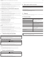 5
5
-
 6
6
-
 7
7
-
 8
8
-
 9
9
-
 10
10
-
 11
11
-
 12
12
-
 13
13
-
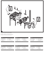 14
14
-
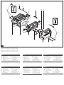 15
15
-
 16
16


AVENTICS Series TC08-TC15 Assembly Instructions
- Typ
- Assembly Instructions
på andra språk
- italiano: AVENTICS Series TC08-TC15
- español: AVENTICS Series TC08-TC15
- Deutsch: AVENTICS Series TC08-TC15
- français: AVENTICS Series TC08-TC15
Relaterade papper
-
AVENTICS LS04 SW Assembly Instructions
-
AVENTICS Series AV Assembly Instructions
-
AVENTICS LS04 SW Bruksanvisning
-
-
-
-
-
-