Blaupunkt TSW 250 Bruksanvisning
- Kategori
- Soundbar-högtalare
- Typ
- Bruksanvisning

TSw 250
TSw 300

– 2 –
Blaupunkt speaker features . . . . . . . . . . . . . . . . . . . . . . . . . . . . . . . . . . . . . . . . . . . . . . . . . . . . . . . . . . . . . . . . . . . . . . . . .4
Safety concerns and installation warnings . . . . . . . . . . . . . . . . . . . . . . . . . . . . . . . . . . . . . . . . . . . . . . . . . . . . . . . . . . . . . .5
Installation tools & guidelines . . . . . . . . . . . . . . . . . . . . . . . . . . . . . . . . . . . . . . . . . . . . . . . . . . . . . . . . . . . . . . . . . . . . . . . .6
System design guidelines . . . . . . . . . . . . . . . . . . . . . . . . . . . . . . . . . . . . . . . . . . . . . . . . . . . . . . . . . . . . . . . . . . . . . . . . . . .7
Subwoofer enclosure types . . . . . . . . . . . . . . . . . . . . . . . . . . . . . . . . . . . . . . . . . . . . . . . . . . . . . . . . . . . . . . . . . . . . . . . . . .8
Active & passive electrical configurations . . . . . . . . . . . . . . . . . . . . . . . . . . . . . . . . . . . . . . . . . . . . . . . . . . . . . . . . . . . . . .9
Basic mathematics for enclosure construction . . . . . . . . . . . . . . . . . . . . . . . . . . . . . . . . . . . . . . . . . . . . . . . . . . . . . . . . . .10
Sample boxes . . . . . . . . . . . . . . . . . . . . . . . . . . . . . . . . . . . . . . . . . . . . . . . . . . . . . . . . . . . . . . . . . . . . . . . . . . . . . . . . . . .11
Final subwoofer enclosure construction . . . . . . . . . . . . . . . . . . . . . . . . . . . . . . . . . . . . . . . . . . . . . . . . . . . . . . . . . . . . . . .12
Additional reference information . . . . . . . . . . . . . . . . . . . . . . . . . . . . . . . . . . . . . . . . . . . . . . . . . . . . . . . . . . . . . . . . . . . . .12
Technical specifications . . . . . . . . . . . . . . . . . . . . . . . . . . . . . . . . . . . . . . . . . . . . . . . . . . . . . . . . . . . . . . . . . . . . . . . . .76-79
Blaupunkt technical support . . . . . . . . . . . . . . . . . . . . . . . . . . . . . . . . . . . . . . . . . . . . . . . . . . . . . . . . . . . . . . . . . . . . . . . .80
Limited warranty information . . . . . . . . . . . . . . . . . . . . . . . . . . . . . . . . . . . . . . . . . . . . . . . . . . . . . . . . . . . . . . . . . . . . .80-81
TABLE OF CONTENTS
Eigenschaften der Blaupunkt-Lautsprecher . . . . . . . . . . . . . . . . . . . . . . . . . . . . . . . . . . . . . . . . . . . . . . . . . . . . . . . . . . . .13
Sicherheitsbelange und Warnungen zur Installation . . . . . . . . . . . . . . . . . . . . . . . . . . . . . . . . . . . . . . . . . . . . . . . . . . . . . .14
Installationswerkzeuge und -anweisungen . . . . . . . . . . . . . . . . . . . . . . . . . . . . . . . . . . . . . . . . . . . . . . . . . . . . . . . . . . . . .15
Richtlinien zur Systemplanung . . . . . . . . . . . . . . . . . . . . . . . . . . . . . . . . . . . . . . . . . . . . . . . . . . . . . . . . . . . . . . . . . . . . . .16
Subwoofer-Gehäusearten . . . . . . . . . . . . . . . . . . . . . . . . . . . . . . . . . . . . . . . . . . . . . . . . . . . . . . . . . . . . . . . . . . . . . . . . . .17
Aktive und passive elektrische Konfigurationen . . . . . . . . . . . . . . . . . . . . . . . . . . . . . . . . . . . . . . . . . . . . . . . . . . . . . . . . .18
Mathematische Grundprinzipien zur Gehäusekonstruktion . . . . . . . . . . . . . . . . . . . . . . . . . . . . . . . . . . . . . . . . . . . . . . . .19
Mustergehäuse . . . . . . . . . . . . . . . . . . . . . . . . . . . . . . . . . . . . . . . . . . . . . . . . . . . . . . . . . . . . . . . . . . . . . . . . . . . . . . . . . .20
Endgültige Konstruktion des Subwoofer-Gehäuses . . . . . . . . . . . . . . . . . . . . . . . . . . . . . . . . . . . . . . . . . . . . . . . . . . . . . .21
Zusätzliche Hinweise . . . . . . . . . . . . . . . . . . . . . . . . . . . . . . . . . . . . . . . . . . . . . . . . . . . . . . . . . . . . . . . . . . . . . . . . . . . . . .21
Technische Daten . . . . . . . . . . . . . . . . . . . . . . . . . . . . . . . . . . . . . . . . . . . . . . . . . . . . . . . . . . . . . . . . . . . . . . . . . . . . . .76-79
Technischer Kundendienst von Blaupunkt . . . . . . . . . . . . . . . . . . . . . . . . . . . . . . . . . . . . . . . . . . . . . . . . . . . . . . . . . . . . .80
Informationen zur beschränkten Garantie . . . . . . . . . . . . . . . . . . . . . . . . . . . . . . . . . . . . . . . . . . . . . . . . . . . . . . . . . . .80-81
INHALTSVERZEICHNIS
Caractéristiques des haut-parleurs Blaupunkt . . . . . . . . . . . . . . . . . . . . . . . . . . . . . . . . . . . . . . . . . . . . . . . . . . . . . . . . . .22
Consignes de sécurité et avertissements relatifs à l’installation . . . . . . . . . . . . . . . . . . . . . . . . . . . . . . . . . . . . . . . . . . . . .23
Directives et outils d’installation . . . . . . . . . . . . . . . . . . . . . . . . . . . . . . . . . . . . . . . . . . . . . . . . . . . . . . . . . . . . . . . . . . . . .24
Directives sur la conception des systèmes . . . . . . . . . . . . . . . . . . . . . . . . . . . . . . . . . . . . . . . . . . . . . . . . . . . . . . . . . . . .25
Types d’enceintes de subwoofers . . . . . . . . . . . . . . . . . . . . . . . . . . . . . . . . . . . . . . . . . . . . . . . . . . . . . . . . . . . . . . . . . . . .26
Configurations électriques actives et passives . . . . . . . . . . . . . . . . . . . . . . . . . . . . . . . . . . . . . . . . . . . . . . . . . . . . . . . . .27
Principes mathématiques de la construction des enceintes . . . . . . . . . . . . . . . . . . . . . . . . . . . . . . . . . . . . . . . . . . . . . . .28
Exemples d’enceintes . . . . . . . . . . . . . . . . . . . . . . . . . . . . . . . . . . . . . . . . . . . . . . . . . . . . . . . . . . . . . . . . . . . . . . . . . . . . .29
Construction finale d’une enceinte de subwoofer . . . . . . . . . . . . . . . . . . . . . . . . . . . . . . . . . . . . . . . . . . . . . . . . . . . . . . .30
Références supplémentaires . . . . . . . . . . . . . . . . . . . . . . . . . . . . . . . . . . . . . . . . . . . . . . . . . . . . . . . . . . . . . . . . . . . . . . . .30
Spécifications techniques . . . . . . . . . . . . . . . . . . . . . . . . . . . . . . . . . . . . . . . . . . . . . . . . . . . . . . . . . . . . . . . . . . . . . . .76-79
Assistance technique de Blaupunkt . . . . . . . . . . . . . . . . . . . . . . . . . . . . . . . . . . . . . . . . . . . . . . . . . . . . . . . . . . . . . . . . . .80
Informations sur la garantie limitée . . . . . . . . . . . . . . . . . . . . . . . . . . . . . . . . . . . . . . . . . . . . . . . . . . . . . . . . . . . . . . . .80-81
ÍNDICE DAS MATÉRIAS
INDICE
Caratteristiche degli altoparlanti Blaupunkt . . . . . . . . . . . . . . . . . . . . . . . . . . . . . . . . . . . . . . . . . . . . . . . . . . . . . . . . . . . .31
Raccomandazioni di sicurezza e avvertenze sull'installazione . . . . . . . . . . . . . . . . . . . . . . . . . . . . . . . . . . . . . . . . . . . . . .32
Attrezzi e istruzioni per l'installazione . . . . . . . . . . . . . . . . . . . . . . . . . . . . . . . . . . . . . . . . . . . . . . . . . . . . . . . . . . . . . . . . .33
Istruzioni per la progettazione dell'impianto . . . . . . . . . . . . . . . . . . . . . . . . . . . . . . . . . . . . . . . . . . . . . . . . . . . . . . . . . . . .34
Tipi di involucri per subwoofer . . . . . . . . . . . . . . . . . . . . . . . . . . . . . . . . . . . . . . . . . . . . . . . . . . . . . . . . . . . . . . . . . . . . . .35
Configurazioni elettriche attive e passive . . . . . . . . . . . . . . . . . . . . . . . . . . . . . . . . . . . . . . . . . . . . . . . . . . . . . . . . . . . . . .36
Calcoli di base per la costruzione dell'involucro . . . . . . . . . . . . . . . . . . . . . . . . . . . . . . . . . . . . . . . . . . . . . . . . . . . . . . . . .37
Scatole campione . . . . . . . . . . . . . . . . . . . . . . . . . . . . . . . . . . . . . . . . . . . . . . . . . . . . . . . . . . . . . . . . . . . . . . . . . . . . . . . .38
Realizzazione finale dell'involucro del subwoofer . . . . . . . . . . . . . . . . . . . . . . . . . . . . . . . . . . . . . . . . . . . . . . . . . . . . . . . .39
Informazioni aggiuntive di riferimento . . . . . . . . . . . . . . . . . . . . . . . . . . . . . . . . . . . . . . . . . . . . . . . . . . . . . . . . . . . . . . . . .39
Specifiche tecniche . . . . . . . . . . . . . . . . . . . . . . . . . . . . . . . . . . . . . . . . . . . . . . . . . . . . . . . . . . . . . . . . . . . . . . . . . . . .76-79
Assistenza tecnica Blaupunkt . . . . . . . . . . . . . . . . . . . . . . . . . . . . . . . . . . . . . . . . . . . . . . . . . . . . . . . . . . . . . . . . . . . . . . .80
Informazioni sulla garanzia limitata . . . . . . . . . . . . . . . . . . . . . . . . . . . . . . . . . . . . . . . . . . . . . . . . . . . . . . . . . . . . . . . .80-81

Características principales de los altavoces de Blaupunkt . . . . . . . . . . . . . . . . . . . . . . . . . . . . . . . . . . . . . . . . . . . . . . . .40
Consideraciones de seguridad y precauciones de instalación . . . . . . . . . . . . . . . . . . . . . . . . . . . . . . . . . . . . . . . . . . . . . .41
Herramientas y guías para la instalación . . . . . . . . . . . . . . . . . . . . . . . . . . . . . . . . . . . . . . . . . . . . . . . . . . . . . . . . . . . . . .42
Guías de diseño para el sistema . . . . . . . . . . . . . . . . . . . . . . . . . . . . . . . . . . . . . . . . . . . . . . . . . . . . . . . . . . . . . . . . . . . . .43
Tipos de caja para subwoofers . . . . . . . . . . . . . . . . . . . . . . . . . . . . . . . . . . . . . . . . . . . . . . . . . . . . . . . . . . . . . . . . . . . . . .44
Configuraciones eléctricas activas y pasivas . . . . . . . . . . . . . . . . . . . . . . . . . . . . . . . . . . . . . . . . . . . . . . . . . . . . . . . . . . .45
Cálculos básicos para la construcción de cajas de altavoces . . . . . . . . . . . . . . . . . . . . . . . . . . . . . . . . . . . . . . . . . . . . . .46
Modelos de cajas . . . . . . . . . . . . . . . . . . . . . . . . . . . . . . . . . . . . . . . . . . . . . . . . . . . . . . . . . . . . . . . . . . . . . . . . . . . . . . . .47
Construcción de la caja del subwoofer . . . . . . . . . . . . . . . . . . . . . . . . . . . . . . . . . . . . . . . . . . . . . . . . . . . . . . . . . . . . . . . .48
Referencias de información adicional . . . . . . . . . . . . . . . . . . . . . . . . . . . . . . . . . . . . . . . . . . . . . . . . . . . . . . . . . . . . . . . . .48
Especificaciones técnicas . . . . . . . . . . . . . . . . . . . . . . . . . . . . . . . . . . . . . . . . . . . . . . . . . . . . . . . . . . . . . . . . . . . . . . .76-79
Apoyo técnico de Blaupunkt . . . . . . . . . . . . . . . . . . . . . . . . . . . . . . . . . . . . . . . . . . . . . . . . . . . . . . . . . . . . . . . . . . . . . . . .80
Información sobre la garantía limitada . . . . . . . . . . . . . . . . . . . . . . . . . . . . . . . . . . . . . . . . . . . . . . . . . . . . . . . . . . . . . .80-81
INDICE
Características do alto-falante Blaupunkt . . . . . . . . . . . . . . . . . . . . . . . . . . . . . . . . . . . . . . . . . . . . . . . . . . . . . . . . . . . . . .49
Medidas de segurança e advertências para a instalação . . . . . . . . . . . . . . . . . . . . . . . . . . . . . . . . . . . . . . . . . . . . . . . . . .50
Ferramentas para a instalação e normas de procedimento . . . . . . . . . . . . . . . . . . . . . . . . . . . . . . . . . . . . . . . . . . . . . . . .51
Princípios do desenho do sistema . . . . . . . . . . . . . . . . . . . . . . . . . . . . . . . . . . . . . . . . . . . . . . . . . . . . . . . . . . . . . . . . . . .52
Tipos de caixa para alto-falante de freqüências graves . . . . . . . . . . . . . . . . . . . . . . . . . . . . . . . . . . . . . . . . . . . . . . . . . . .53
Configurações elétricas ativas e passivas . . . . . . . . . . . . . . . . . . . . . . . . . . . . . . . . . . . . . . . . . . . . . . . . . . . . . . . . . . . . .54
Cálculos básicos matemáticos para a construção da caixa do alto-falante . . . . . . . . . . . . . . . . . . . . . . . . . . . . . . . . . . .55
Exemplos de caixas . . . . . . . . . . . . . . . . . . . . . . . . . . . . . . . . . . . . . . . . . . . . . . . . . . . . . . . . . . . . . . . . . . . . . . . . . . . . . .56
Construção final da caixa do alto-falante de freqüências graves . . . . . . . . . . . . . . . . . . . . . . . . . . . . . . . . . . . . . . . . . . . .57
Informação para referência adicional . . . . . . . . . . . . . . . . . . . . . . . . . . . . . . . . . . . . . . . . . . . . . . . . . . . . . . . . . . . . . . . . .57
Especificações técnicas . . . . . . . . . . . . . . . . . . . . . . . . . . . . . . . . . . . . . . . . . . . . . . . . . . . . . . . . . . . . . . . . . . . . . . . .76-79
Assistência técnica da Blaupunkt . . . . . . . . . . . . . . . . . . . . . . . . . . . . . . . . . . . . . . . . . . . . . . . . . . . . . . . . . . . . . . . . . . . .80
Informação sobre os limites de garantia . . . . . . . . . . . . . . . . . . . . . . . . . . . . . . . . . . . . . . . . . . . . . . . . . . . . . . . . . . . .80-81
ÍNDICE DAS MATÉRIAS
Blaupunkthögtalarens egenskaper . . . . . . . . . . . . . . . . . . . . . . . . . . . . . . . . . . . . . . . . . . . . . . . . . . . . . . . . . . . . . . . . . . .58
Säkerhetsrisker och installationsvarningar . . . . . . . . . . . . . . . . . . . . . . . . . . . . . . . . . . . . . . . . . . . . . . . . . . . . . . . . . . . . .59
Installationsverktyg och riktlinjer . . . . . . . . . . . . . . . . . . . . . . . . . . . . . . . . . . . . . . . . . . . . . . . . . . . . . . . . . . . . . . . . . . . . .60
Riktlinjer för systemkonstruktion . . . . . . . . . . . . . . . . . . . . . . . . . . . . . . . . . . . . . . . . . . . . . . . . . . . . . . . . . . . . . . . . . . . . .61
Typer av subwooferlådor . . . . . . . . . . . . . . . . . . . . . . . . . . . . . . . . . . . . . . . . . . . . . . . . . . . . . . . . . . . . . . . . . . . . . . . . . . .62
Aktiva och passiva elektriska konfigurationer . . . . . . . . . . . . . . . . . . . . . . . . . . . . . . . . . . . . . . . . . . . . . . . . . . . . . . . . . . .63
Grundläggande matematik för lådkonstruktion . . . . . . . . . . . . . . . . . . . . . . . . . . . . . . . . . . . . . . . . . . . . . . . . . . . . . . . . . .64
Modellådor . . . . . . . . . . . . . . . . . . . . . . . . . . . . . . . . . . . . . . . . . . . . . . . . . . . . . . . . . . . . . . . . . . . . . . . . . . . . . . . . . . . . . .65
Slutlig lådkonstruktion för subwoofer . . . . . . . . . . . . . . . . . . . . . . . . . . . . . . . . . . . . . . . . . . . . . . . . . . . . . . . . . . . . . . . . .66
Ytterligare hänvisningsinformation . . . . . . . . . . . . . . . . . . . . . . . . . . . . . . . . . . . . . . . . . . . . . . . . . . . . . . . . . . . . . . . . . . .66
Tekniska specifikationer . . . . . . . . . . . . . . . . . . . . . . . . . . . . . . . . . . . . . . . . . . . . . . . . . . . . . . . . . . . . . . . . . . . . . . . . .76-79
Blaupunkts tekniska support . . . . . . . . . . . . . . . . . . . . . . . . . . . . . . . . . . . . . . . . . . . . . . . . . . . . . . . . . . . . . . . . . . . . . . . .80
Information om begränsad garanti . . . . . . . . . . . . . . . . . . . . . . . . . . . . . . . . . . . . . . . . . . . . . . . . . . . . . . . . . . . . . . . . .80-81
INNEHÅLLSFÖRTECKNING
– 3 –
INHOUDSOPGAVE
Kenmerken Blaupunkt luidsprekers . . . . . . . . . . . . . . . . . . . . . . . . . . . . . . . . . . . . . . . . . . . . . . . . . . . . . . . . . . . . . . . . . .67
Veiligheidsinstructies en installatiewaarschuwingen . . . . . . . . . . . . . . . . . . . . . . . . . . . . . . . . . . . . . . . . . . . . . . . . . . . . . .68
Gereedschappen en richtlijnen voor installatie . . . . . . . . . . . . . . . . . . . . . . . . . . . . . . . . . . . . . . . . . . . . . . . . . . . . . . . . . .69
Richtlijnen voor systeemontwerp . . . . . . . . . . . . . . . . . . . . . . . . . . . . . . . . . . . . . . . . . . . . . . . . . . . . . . . . . . . . . . . . . . . .70
Typen subwooferboxen . . . . . . . . . . . . . . . . . . . . . . . . . . . . . . . . . . . . . . . . . . . . . . . . . . . . . . . . . . . . . . . . . . . . . . . . . . . .71
Actieve & passieve elektrische configuraties . . . . . . . . . . . . . . . . . . . . . . . . . . . . . . . . . . . . . . . . . . . . . . . . . . . . . . . . . . .72
Basisberekeningen voor constructie boxen . . . . . . . . . . . . . . . . . . . . . . . . . . . . . . . . . . . . . . . . . . . . . . . . . . . . . . . . . . . .73
Voorbeeldboxen . . . . . . . . . . . . . . . . . . . . . . . . . . . . . . . . . . . . . . . . . . . . . . . . . . . . . . . . . . . . . . . . . . . . . . . . . . . . . . . . .74
Eindconstructie subwooferboxen . . . . . . . . . . . . . . . . . . . . . . . . . . . . . . . . . . . . . . . . . . . . . . . . . . . . . . . . . . . . . . . . . . . .75
Extra referenties . . . . . . . . . . . . . . . . . . . . . . . . . . . . . . . . . . . . . . . . . . . . . . . . . . . . . . . . . . . . . . . . . . . . . . . . . . . . . . . . .75
Technische specificaties . . . . . . . . . . . . . . . . . . . . . . . . . . . . . . . . . . . . . . . . . . . . . . . . . . . . . . . . . . . . . . . . . . . . . . . .76-79
Technische ondersteuning Blaupunkt . . . . . . . . . . . . . . . . . . . . . . . . . . . . . . . . . . . . . . . . . . . . . . . . . . . . . . . . . . . . . . . . .80
Informatie met betrekking tot de beperkte garantie . . . . . . . . . . . . . . . . . . . . . . . . . . . . . . . . . . . . . . . . . . . . . . . . . . .80-81

THANK YOU FOR CHOOSING BLAUPUNKT!
KEY FEATURES
– 4 –
Congratulations! You are the now the owner of an exceptional loudspeaker from the audio enthusiasts at Blaupunkt. Our
engineering staff has spent considerable time refining our subwoofers in order to introduce great sound to the consumer
at an affordable price. But now, we have evolved the speaker design with a new TPC cone material and the aggressive
TPB baskets.
Not only do we offer you a great product but also a supportive owners manual. Although technically informative, we are
also are very concerned about the end consumer using proper installation techniques for the highest performance
possible from their new loudspeakers. MOST important to us are concerns with safety and the installation process.
Since our Blaupunkt retail dealers have the tools and experience for an optimized and safe installation, we always
recommend they do the final vehicle integration. But, should you choose to install these products yourself, please take
the time to read this manual completely and abide by all precautions.
It has been repeatedly proven that remarkably high audio system performance can be achieved by moderately priced
components. Our subwoofers are designed for HIGH POWER HANDLING LEVELS, HIGH SOUND PRESSURE LEVELS,
and FLEXIBLE INSTALLATION CHOICES.
The focus on our new subwoofers is the TPC cone material offering lighter mass compared to older paper cones but
without the flexing properties common to paper. This gives a much “tighter” bass response without distortions often
found at high listening levels. Below is a good summary comparing old cones with the new technologies. We also
present the incredible TPB basket technology.
In addition to the TPC cones is the expansion of our extended pole program. The extended pole piece of the subwoofer
is lengthened by a few millimeters but the performance results are significant. The non-linear fields around the voice
coil’s gap are greatly reduced thus improved heat dissipation (higher power handling) and increased cone movement
control (higher power but with “cleaner” response).
TPB – TRANSPARENT
POLYCARBONATE BASKET
• ACOUSTICALLY INERT: Unlike metal
baskets, the TPB baskets don’t create
additional sound via sympathetic vibration
with the cone. They also don’t require
sound-dampening coating to reduce the inherent vibration typical of metal
baskets.
•WATER RESISTANT: The Polycarbonate basket also encapsulates the
magnet structure so the speaker is inherently water resistant, allowing
it’s use in outdoor and marine applications.
• INSTALLER FRIENDLY: The TPB baskets are very Installer friendly with
their ability to be easily drilled for additional mounting holes. If there
are slight curves or bumps in the mounting panel the plastic rim will
conform ensuring a good front/rear air seal.
• SEE THROUGH: The TPB baskets allow the user to see the inner
workings of a speaker like never before. Add some back-lighting for a
stunning installation.
TPC – TRANSPARENT POLYMER
CONE
• LIGHTWEIGHT: The TPC injected plastic
cones are lightweight and mechanically rigid,
allowing the speakers to play louder with less
power than conventional paper or poly cones.
• ACOUSTICALLY INERT: The TPC cones move the air in as linear as
possible. This creates an ‘up front’ sound without adding ‘coloration’ to
the original recording.
• ENVIRONMENTALLY RESILIENT: Shape and thickness of the TPC cones
are rigidly controlled in the manufacturing process. This ensures premium
sound accuracy from speaker to speaker and maintains sound accuracy
for many years to come.
• SEE THROUGH: TPC cones allow the user to see inside the speaker.
With simple back-lighting, the visual effects of the TPC cones moving with
the beat of the music are captivating.
“EXP” Extended Pole Design
• Increased cone travel for higher “clean” sound pressure levels
• More symmetrical magnetic operating field for lower distortion
• Better heat dissipation offering higher power handling capability
Conventional Magnetic Pole Design
• Limited linear cone travel (high level distortion at lower volume
levels)
• Uneven magnetic field distribution throughout cone travel (common
distortions)
• Average heat dissipation (therefore only average power handling)

Before disassembling your beautiful new car you need some basic installation knowledge and skill with common hand
and power tools. Following such basic installation tips and warnings will prevent possible damage to the vehicle and
also prevent possible fires.
■
AGAIN...READ THE MANUAL! There is a lot of helpful information in this manual that will
save time and prevent problems later.
■
COVER THE VEHICLE WORK AREAS - Use fender covers or blankets to protect the work
areas from scratches or dings.
■
DISCONNECT THE (-) LEAD ON THE BATTERY - No sparks or fires please!
■
“REVIEW” THE INSTALLATION - Before using any tools or moving vehicle components, take
five minutes to review the installation intentions (e.g., verify that an enclosure will fit in an
area of a car before tearing out all the interior).
■
“REVIEW” THE VEHICLE - Before drilling any holes or cutting into any surfaces, make sure
there are no fuel or hydraulic lines behind the surfaces. Also make sure there are no wires
routed directly behind or near the desired mounting area (remember...screws can often
extend 1-2 inches behind the mounting surface).
■
ENSURE PROPER FIT - Before cutting or drilling, make sure the speaker will physically fit in
its desired location. Check for clearance around rear deck torsion bars or other structural
elements.
■
EVERY CAR IS ASSEMBLED DIFFERENT - Every auto manufacturer uses different assembly techniques. Take care in
removing/modifying all trim panels and mounting surfaces since they often use unique screws or snap fasteners that
are difficult to replace if they are lost or broken.
■
BE CAREFUL WITH CABLE ROUTING - When routing audio cables, make sure RCA and speaker wires are routed
away from high current power lines for audio amplifiers and vehicle systems lines when possible. This will help prevent
noises from creeping into the audio system, plus prevent potential damage to the vehicle wiring itself.
■
BE CARFUL WITH ALL CONNECTIONS - When making connections, make sure each connection is clean and properly
secured. Observe all polarity markings carefully to ensure proper end performance.
■
CAUTION - FUEL TANKS AND FUEL LINES ARE NOW LOCATED DIRECTLY BENEATH THE REAR DECK IN MANY
CARS - CHECK FOR ADEQUATE CLEARANCE BEFORE EVEN CONSIDERING SUCH A MOUNTING LOCATION!
SAFETY CONCERNS
INSTALLATION WARNINGS!
– 5 –
We always recommend you have your Blaupunkt speakers professionally installed but the installation process is often so
easy that the average consumer can achieve success with little trouble. Regardless of the person installing, you should be
sure to review the following points before proceeding with the installation:
■
READ THE MANUAL! Understanding the product and installation limitations before lifting a
screwdriver.
■
WEAR SAFETY GLASSES AT ALL TIMES - Flying debris are always dangerous.
■
PROTECT THE VEHICLE - Always disconnect the negative battery cable before starting
any kind of installation work. This prevents a possible high current electrical short
(potential fires).
■
HEAT - Keep all speakers away from nearby hot components such as amplifiers or vehicle
components that heat up over time such as hoses, high current wires, and braking system
components.
■
GIVE YOURSELF LOTS OF TIME - Rushing to complete an installation nearly always ends
up with problems.
■
DO NOT LISTEN AT HIGH SOUND LEVELS FOR A PROLONGED TIME - If connected to high power amplifiers, these
speakers have the potential to cause permanent hearing loss after listening at maximum volume levels for several hours.

For most installations, simple hand tools are adequate if replacing the factory speakers. If the factory locations, or other
convenient mounting locations are not used, you will need power tools for drilling and cutting plastics and metal. A good
starting list is summarized below:
■
Tape measure and ruler
■
Marking pen and starting punch
■
Phillips and flat blade screwdrivers (small and medium sizes)
■
Nylon wire bundle ties
■
Pliers: standard vice-grip and needle nose styles
■
Light-duty trim pry-bar for removing door trim
■
Cutting shears or nibbling tool for cutting thin and medium gauger metal
■
Wire cutters, wire strippers, electrical tape, crimping pliers and appropriate
crimp-on terminals
■
Power drill with appropriate sized drill bits (1/8", 3/16", and 1/4" to start)
■
Electric jig-saw (sabre saw)
We strongly recommend that you have your Blaupunkt speakers professionally installed. If you choose to do your own
installation please note the following important information:
■
Before cutting any trim or metal make sure your final installation will clear all moving parts, factory cables, wires, and
hoses.
■
Be sure to leave enough slack in the wiring to prevent the need to pull or street wires if service is needed later.
■
Tie down all loose wires with nylon wire ties to prevent them from getting caught in moving parts or shorted out due to
abrasions from moving over time.
■
Never mount speakers in a vehicle’s wheel wells or areas where they may be subjected to moisture or road spray.
■
Proper speaker polarity must be observed. The polarity positive side is marked by a (+) symbol or a red colored dot.
At low frequencies woofers out of phase will acoustically cancel one another thus resulting in little bass output.
■
Although components used in Blaupunkt speakers exceed most production quality standards, speaker frames can still
be twisted by improper installation on uneven surfaces.
■
This can occur when surfaces are heavily padded or carpeted and the screws are unevenly tightened or over
tightened. The results will be a damaged voice coil assembly due to knocking it off center.
■
When installing more than one speaker per amplifier channel be sure that the combined impedance values will not
damage the amplifier should they be too low (i.e., a common minimum impedance value of 2 ohms is common).
■
Speaker wire size should be sufficient to carry the full power of the amplifier (16 gauge or larger is sufficient in about
90% of all audio systems assuming <100 watt amplifiers and wire runs under 20 feet)
■
Speaker wires should be electrically and physically isolated from the vehicle and routed away from any factory wiring
that carries high currents or noises (e.g., ABS brake systems and engine computer signals)
FINAL SYSTEM TEST & TROUBLESHOOTING
Once the system is installed, turn on the total audio system main power switch and SLOWLY turn the volume up using a
music selection with a full range of frequencies. If you experience any of the following problems take corrective action
immediately to prevent damage to the speaker, amplifier, and vehicle.
INSTALLATION TOOLS
INSTALLATION GUIDELINES
– 6 –
NO SOUND AT ALL -or-
VERY LOW SOUND LEVELS
Verify the amplifiers are on and gain controls at mid-position
Verify RCA level signals exist with small test amplifier
Verify power, ground, and RCA cabling to all channels is correct
Verify adequate voltage to the amps (12-14 volts in most vehicles)
Install another outboard speaker at the amp to see if sound comes out
Replace the amplifier
Verify adequate voltage to the amps (12-14 volts in most vehicles)
Check that speaker load impedances are 2 ohms or greater per
channel
Check for a pinched wire or wire shorted to vehicle ground somewhere
Lower input gain to amp - you may be over-driving the input stage
The amp must have adequate ventilation - it may be getting too hot
POWER AMP CYCLES ON/OFF -or-
HIGH DISTORTION LEVELS

SYSTEM DESIGN GUIDELINES
– 7 –
SYSTEM PLANNING
The largest possible impact on any audio system (home or car) is the tonal quality of the loudspeakers, their respective
placement, and their overall efficiency (loudness). A 4x20 watt amplifier and four dual-cone speakers is never going to make
an impressive performance. The first major improvement comes with the addition of a strong low frequency performance
which give the emotional sensation of “strength” to the audio system. Often many newer cars have acceptable coaxial
speakers in acceptable mounting locations. By adding a subwoofer speaker and amplifier, the system, although only
moderate performance, becomes surprisingly pleasant for most listeners. To move to the next step up in performance you
must install some good component speakers for the mids and highs (“satellite” speakers) then add a separate subwoofer
speaker for the lows.
SYSTEM IMPLEMENTATION
Speaker configurations are a common problem in autosound installations. We want to achieve a sound field in front of us
(like a live concert) as compared to sound partly from the front and partly behind us. This dictates good midrange and
tweeter speakers in front, usually mounted in the doors for good left/right balance, with high-pass crossovers set greater than
80-100 Hz. The best stereo image will occur when the front speakers are spaced as far forward as possible attempting to
achieve nearly equal distance from the speakers to the listening position. For deep bass a subwoofer is required but is nearly
always located behind us in a rear trunk or rear hatch area. If the subwoofer crossover is too high in frequency male voices
can be heard “gurgling” out of the subwoofer speaker and therefore pulls the sound-stage to the rear of the car, which is very
unnatural and therefore undesirable.
MULTI-CHANNEL SYSTEMS
Moving up to amplifiers around 4x50 watts on the satellite channels with component speakers is a common and acoustically
rewarding step. The improvements in acoustical left/right balance and stereo imaging are quickly obvious. By adding a
dedicated subwoofer amplifier the perceived “strength” of the system is
often dramatic.
In order to achieve such a multi-channel system a dividing network must
be installed that keeps the low frequencies out of the midrange speakers.
Such a “crossover” network directs the higher and lower frequencies to
their respective drivers. Such a crossover can be “passive” (simple coils
and capacitors) that limit the operating frequencies seen by their
respective speakers. A crossover can also be “active” where an
electronic box must be installed in front of a dedicated amplifier and
process the signal via small signal RCA cables before its amplification. In
general, active crossovers are most common for the low/mid transition
area because they best filter the low frequencies and are physically small
compared to the passive equivalent. Passive crossovers are most often
used where they provide adequate filtering in the mid/high frequency
transition with satellite midranges and their tweeters. Passive crossovers
at these higher frequencies require only small coils and capacitors so
they are easy to install and perform well.
AMPLIFIER POWER
Amplifier choice and power is important but less so compared to speaker choice and placement. Matching the rms
(continuous) power capability to that of the speaker is important but it should be noted that “under-powering” a system can
often damage more tweeters than providing slightly more power than stated by the speakers. If the speakers are rated to 50
watts rms, you can often run 60-80 watt rms amplifiers without concern IF
the amps are not driven into clipping (deep
distortion). IMPEDANCE is the electrical resistance to AC current flow and is typically 4 ohms for most car speakers.
Impedance loads should not fall below the manufacturer’s recommended minimum impedance or the amp will heat up and
sometimes shut down (2 ohms/channel is common).
SOUND QUALITY VS. LOUDNESS
All well designed sound system can provide good sound quality and still play loud. Above about 120 dB (decibels) the sound
isn’t perceived as getting much louder due to the non-linearities of the human ear. A four loudspeaker system with the per-
speaker efficiency rating of 90 dB (1 watt/1 meter) will often achieve about 110-115 dB if driven by 100 watts per speaker
channel. (Although often debated, this is more than enough sound pressure level for most humans to enjoy and can easily
cause hearing loss if listened to at such levels for hours at a time.)
Tuner
Passive X-over Sat Amplifier (4x100 W)
Sub Amplifier (2x100 W) Subwoofers

SUBWOOFER ENCLOSURE TYPES
In the car audio world there are 5 types of subwoofer enclosures commonly used; Infinite Baffle, Sealed Box, Vented
Box, Single-Vented Band-Pass, and Dual-Vented Band-Pass. No single design is superior because each has its own
compromises in performance, power handling, and design/construction complexity. You need to make the choice based
upon personal listening habits and requirements.
Having “Multi-Box” design characteristics, your Blaupunkt subwoofer performs remarkably well in ALL installations, but
is optimized for Sealed, Vented, and Single-Vented Band-Pass configurations due to its moderate Qts values. Below is a
summary of these 5 popular enclosures. More importantly their respective advantages and disadvantages are noted so
an intelligent choice can be made regarding the best box for you.
INFINITE BAFFLE is simply a woofer installed in the back shelf of the car that uses the
trunk as the enclosure. Advantages: simple installation and adequate performance;
Disadvantages: only moderate sound pressure levels and poor power handling.
SEALED BOX (a.k.a. “Closed Box”) offers one of the best compromise in performance
and power handling. Advantages: simple box construction, high power handling,
excellent transient response, and smooth low frequency roll-off. Disadvantages:
moderate to large box sizes, moderate efficiency, moderate sound pressure levels.
VENTED BOX (a.k.a. “Ported Box” and “Bass Reflex”) is simply a sealed box but with a
specifically tuned tube inserted. It extends the low frequency response compared to a
sealed box. Advantages: low cut-off frequency, low distortion in its operating pass-
band, excellent efficiency, good transient response, moderate power handling (in its
pass-band), and small box sizes. Disadvantages: complex design and limited power
handling if driven hard at very low frequencies (below port tuning frequency).
SINGLE-VENTED BAND-PASS (a.k.a. “4th Order Band-Pass”) is one of the best
designs for the car. It is basically a “compromise” between a sealed and vented box in
performance and reliability. Advantages: small box volumes, extended low frequency
performance, and can be used with VERY high power amplifiers. Disadvantages: slight
drops in efficiency compared to a vented box and increased box design and
construction complexity.
DUAL-VENTED BAND-PASS (a.k.a. “6th Order Band-Pass) is unfortunately often used
in the car as an acoustical “fog-horn” - lots of high-SPL but marginal tonal quality if the
enclosure isn’t precisely constructed. Advantages: tr
emendous SPL’s from VERY small
boxes Disadvantages: VERY complex construction and susceptibility to cone over-
excursions for frequencies outside its operating region if a high quality electrical filter is
not used.
– 8 –

– 9 –
At some point, the subwoofer speaker must be electrically connected to an audio amplifier, be it a dedicated bass-only
amp or the amplifier built inside the radio. Clearly, the highest performance level will be from the outboard dedicated amp
due to its typically higher power (e.g., 100 watt amp vs. 20 watts from the radio). To avoid disappointing performance we
recommend power amps with rms power levels exceeding 50 watts if possible. This is NOT
a minimum value; it is simply
a nice power point where you begin to really FEEL the substantial improvements in sound offered by a good
subwoofer/amplifier system.
Now that we have concluded that an outboard dedicated subwoofer amplifier is needed for optimum performance we
must somehow process the signal in order to limit the audio signals to only low frequencies. This must be done via a
“crossover” which can be “active” or “passive”. As stated earlier in this manual, the active system is preferred due to its
small size and better frequency contouring. But it must be placed in front of the amplifier and process the signals via the
RCA cables. This is rarely a problem in most installations.
The passive design is more of a “brute force” process requiring large inductors and capacitors but it is often a “cheap
and dirty” way to get bass response into the car quickly and without noise problems sometimes associated with active
crossovers. Its bigger advantage is when you wish to operate in a combination stereo high-pass/bridged subwoofer
mode common with 2 channel amps. Such configurations are shown in the manuals of most amplifiers. Below is a simple
summary showing how to connect such a passive installation.
ACTIVE AND PASSIVE ELECTRICAL CONFIGURATIONS
A
CTIVE
C
ROSSOVER
S
YSTEM
P
ASSIVE
C
ROSSOVER
S
YSTEM
Active Crossover
Radio Crossover Amp
Radio Amp
Radio Amp
(L)
(L)
(C)
Passive Crossovers
6 db/Octave Crossover
12 db/Octave Crossover
OUTPUT
FREQUENCY
12 db/oct
6 db/oct
Crossover Freq.
(Hz)
80
100
150
200
8.0
6.4
4.2
3.2
Inductor Value (L)
(mH)
Crossover
Freq.
(Hz)
Inductor
Value (L)
(mH)
Capacitor
Value (C)
(uF)
80
100
150
200
350
280
180
140
11.5
9.0
6.0
4.5

– 10 –
AREA AND VOLUME CALCULATIONS
Although many enclosures can now be purchased in prefabricated form, building your own enclosure is often fun,
acoustically rewarding, or even a necessity to properly fit many vehicles. In order to build such a box there MUST be a
basic understanding of mathematic principals or you will wind up wasting incredible amounts of time and money by
making mistakes in the box design and assembly.
BASIC MATHEMATICS FOR ENCLOSURE CONSTRUCTION
The areas of surfaces
or openings are
calculated in square
inches (in2). Such
calculations depend
upon height and width
values or diameters for
circles
d
w
h
w
h
AREAS
circle or a hole rectangular wall or area triangle wall or area
AREA CALCULATIONS
Circle or hole Area = 0.79 x d x d
Rectangular wall or area Area = h x w
Triangle wall or area Area = 0.5 x h x w
The volumes of
assemble shapes are
measured in cubic
inches (in3). Such
calculations depend
upon height, width, and
depth calculations for
rectangular shapes and
a diameter and height
for a tube shape.
AREA AND VOLUME CONVERSIONS
Technical data for speakers are often given in English and Metric unit values (e.g., inches and meters). Also, when
calculating dimensions we must often flip between size formats (e.g., cubic inches and cubic feet). To easily convert
back and forth between two formats you can use the conversion table below.
h
d
h
d
d
w
h
h
d
VOLUMES
tube shape rectangular shape triangular/wedge shape cone shape
d
VOLUME CALCULATIONS
Cylinder (port tube) Volume = 0.79 x d x d x h
Rectangular box Volume = h x w x d
Triangular box Volume = 0.5 x h x w x d
Cone shape Volume = 0.26 x d x d x h
VOLUME AND AREA CONVERSIONS
TO CONVERT YOUR NUMBER FROM: MULTIPLY YOUR NUMBER BY: TO GET A NEW VALUE IN
Inches 0.0254 Meters
Meters 39.37 Inches
Square inches 0.007 Square feet
Square feet 144 Square inches
Cubic inches 0.00058 Cubic feet
Cubic feet 1728 Cubic inches
Liters 0.035 Cubic feet
Cubic feet 28.3 Liters

– 11 –
This page is offered ONLY as a “starting point” for box construction. Although our woofers work well in a wide range of
box volumes, many people try to build boxes too large assuming they will get better bass response with such monstrous
sized boxes. This is NOT acoustically correct and you need to pay attention to the recommended volumes and predicted
performance data when making your box decision. On the other hand, the more common mistake is to jam a big woofer
in an extremely small box and have virtually no low frequency response due to the “choking” effect of an undersized box.
To help understand how large a “cubic foot” really is we have provided the drawings and tables below with some
common relationships for height, width, and depth. These are not “magical” sizes or relationships in any way, just
popular sizes that will fit in most vehicles and perform well.
All dimensions are stated for exterior sizes and are calculated with compensations for box wall thickness using 3/4"
wood. Also, each volume is adjusted for air volume displacements for a woofer (average 0.15 cu ft for 10/12" woofer)
and a mid size port (3" dia. x 7" long). Please be aware of the small impact that box size fluctuations has on the end
sound quality: loudspeaker enclosure interior size deviations of +/- 5% from ideal are rarely heard. In addition, interior
objects such as port volume displacements and cross braces can usually be forgotten about in all but the smallest of
boxes.
BLAUPUNKT SAMPLE ENCLOSURE SIZES
SIMPLE RECTANGULAR BOX (outside dimensions in inches)
Nominal Interior Volume height width depth
(cu. ft.) (h) (w) (d)
0.5 14 15 8
1.0 14 16 12
1.5 16 20 12
2.0 16 26 12
3.0 18 33 12
4.0 18 36 14
SIMPLE “WEDGE” BOX (outside dimensions in inches)
Nominal Interior Volume height width depth depth
(cu. ft.) (h) (w) (d1) (d2)
0.5 14 15 6.5 9.5
1.0 14 16 10.5 13.5
1.5 16 20 10.5 13.5
2.0 16 26 10.5 13.5
3.0 18 33 10.5 13.5
4.0 18 36 12.5 15.5
h
d
w
d
w
d2
d1
h

– 12 –
The following is a list of materials and sources of recommended reading for the person interested in loudspeakers,
acoustics, and audio in general. Subjective comments are noted for each.
■
DESIGNING, BUILDING, AND TESTING YOUR OWN SPEAKER SYSTEM, David Weems, Copyright 1984, TAB Books
#1964, Blue Ridge Summit, PA 17294. (This is an excellent introductory book on designing speakers for the home but is
quite applicable to the car since many concepts are carried over.)
■
LOUDSPEAKER DESIGN COOKBOOK, Vance Dickason, copyright 1991-2002, distributed by Old Colony Sound Lab,
Peterborough, NH, 03458. (A significant technical step up from Weems addressing complex woofer box and crossover
designs. A tremendous reference book useful for all.) ISBN: 1-882580-33-8
■
BLAUBOX WOOFER BOX DESIGN COMPUTER PROGRAM, Thomas Breithaupt, Blaupunkt div. Robert Bosch
Corporation, 2800 S. 25th Avenue, Broadview, IL 60155. (This is a simple to use IBM PC computer program used to
predict the frequency response of a subwoofer in 10 different enclosures including sealed, vented, and bandpass
configurations. Basic passive crossover designs are covered as well. It is provided free of charge as a download from the
Blaupunkt Internet site at: http://www.blaupunkt.com.)
■
TESTING LOUDSPEAKERS, Joseph D’Appolito, copyright 1998, distributed by Old Colony Sound Lab, Peterborough,
NH, 03458, (Outstanding technical reference on measuring loudspeakers-NOT for the feint of heart!) ISBN: 1-882580-17-6
ADDITIONAL REFERENCE INFORMATION
Before final design, wood cutting, and assembly of the enclosure some basic box construction issues need to be
understood. These items are acoustically related, some are construction tips, and some are simply to ensure a long lasting
product for the listener.
■
Infinite baffles are simply a piece of wood holding up the woofer to the back deck of a car. If you chose this installation
(which is generally a poor performer) you must take great care in sealing/caulking all holes that vent into the back seat for
proper bass response.
■
Wedge shaped boxes are simply a triangular box added to a rectangular box.
■
Mathematically add up the volumes of these two boxes and you have the total of a wedge shaped box.
■
When making the calculations, be sure to adjust interior box volumes for port volumes and woofer displacement volumes.
■
All calculations should be made in advanced of cutting wood out. If the final box is off by +/- 5% of optimum values don’t
worry about it; you will rarely be able to hear the difference! This is very important since prefabricated boxes often work
well even if off a little bit. Also, if you do forget to compensate for woofer and port tube volume displacement, it is rarely
acoustically noticed by most people.
■
Very low frequencies simply do not care about the shape of the box. Such wavelengths allow for nearly any reasonable
shape or length but really odd shapes should be avoided so they can be easily cut and glued.
■
Particle board, MDF, or high grade birch plywood are good materials to build boxes with thicknesses of 5/8"-1"
(14-25mm). Solid wood panels should actually be avoided of splitting and warping over time in the car environment.
■
All seams in the box should be glued, screwed, then caulked to prevent panel separation and air leaks over time.
■
Cross bracing of panels is important for large boxes to prevent the panels them selves from radiating sound.
■
Acoustical damping material (e.g., fiberglass batting material 2-4" thick) should cover about 50% of the interior walls.
This helps reduce high frequency resonances and increase the box volume as seen by the woofer by about 10-15%.
■
Spraying the interior walls of the box with a damping material such as tar based automotive undercoating is one of the
best things to help dampen wall resonances.
■
The final box should allow for servicing the woofer at a later time should it be damaged for any reason.
■
5-way binding posts mounted on the box for electrical connections are highly recommended. It is then easy to remove
the box from the vehicle for service or theft protection.
■
Where possible, use the largest diameter port tubes to prevent wind noise. PVC plumbing pipe is inexpensive and is
common in 3, 4, and 5" diameters. PVC “elbow” connectors allow you to make turns inside the box with the average
diameter being along the centerline of the tube.
■
Try to always use active (electronic) crossovers. Today, most power amps have them built in. The mounting distance from
the side of the woofer and the port should be less than 12" or so if possible. Regarding simple vented boxes, you
CANNOT achieve lower frequency response by simply lowering the port tuning frequency from its recommended value.
This severely over-damps the box and results in a very “muddy” sound for the box.
Before gluing and screwing everything together, lightly “tack nail” the sides together and make sure the box fits in the
vehicle. Also, look carefully to see if the woofer magnet has enough depth of clearance from the back wall. There are many
other things to think about when design and building subwoofer boxes but they are too numerous to mention here. But, for
those interested, please refer to some of the related reading for more information on speakers and audio in general.
FINAL SUBWOOFER ENCLOSURE CONSTRUCTION

DANKE, DASS SIE SICH FÜR BLAUPUNKT ENTSCHIEDEN HABEN!
HAUPTFUNKTIONEN
– 13 –
Herzlichen Glückwunsch!! Sie sind nun der Besitzer eines außergewöhnlichen Lautsprechers aus dem Hause der
Audioenthusiasten von Blaupunkt. Unsere Ingenieure haben lange daran gearbeitet, unsere Komponenten zu verfeinern, um
dem Verbraucher großartigen Sound zu erschwinglichen Preisen anbieten zu können. Jetzt haben wir das Lautsprecherdesign
mit einem neuen TPC-Material für Membranen und den offensiven TPB-Körben weiterentwickelt.
Wir bieten Ihnen nicht nur ein großartiges Produkt, sondern auch ein hilfreiches Benutzerhandbuch. Dieses Handbuch kann
als Lehrbuch benutzt werden, da es bündige aber informative Erklärungen über Lautsprecher und Gehäusekonstruktion
bietet, sowie auf andere moderne Literatur und Computerinformationen verweist. Es war uns außerdem sehr wichtig,
Endverbrauchern Installationstechniken zu vermitteln, die aus ihren neuen Lautsprechern die beste Leistung herausholen
können. Am ALLERWICHTIGSTEN für uns waren die Sicherheit und der Installationsvorgang. Da unsere Blaupunkt-Verkäufer
die Werkzeuge und Erfahrung haben, um die Installation optimal und sicher durchzuführen, empfehlen wir immer, dass sie den
endgültigen Einbau in das Fahrzeug übernehmen. Sollten Sie sich aber dafür entscheiden, diese Produkte selbst zu
installieren, nehmen Sie sich bitte die Zeit zum Durchlesen dieses Handbuches und befolgen Sie alle Vorsichtsmassnahmen.
Es ist mehrfach nachgewiesen worden, dass selbst kostengünstige Komponenten erstaunlich hohe Audiosystemleistung
erreichen können. Unsere Subwoofer wurden für HOCHLEISTUNGSPEGEL, HOHE SCHALLDRUCKPEGEL sowie
FLEXIBLE WAHL DER INSTALLATION entwickelt.
Der Kernpunkt unserer neuen Subwoofer ist das TPC- (hochtemperiertes Polycarbonat) Material der Membrane, das
leichter als die älteren Papiermembranen ist, aber nicht die beweglichen Eigenschaften des Papiers nachweist. Dies führt
zu “engerer” Bassresonanz ohne Verzerrungen wie sie normalerweise bei hohen Lautstärken üblich sind. Weiter unten
finden Sie einen guten Vergleich der alten Membranen mit den neuen Technologien. Wir präsentieren Ihnen außerdem die
neue TPB- (hochtemperierte Polycarbonat-Korb) Technologie.
Zusätzlich zu den TPC-Membranen wurde auch das „verlängerte Pole“-Programm erweitert. Der verlängerte Polkern des
Subwoofers wurde nur um einige Millimeter verlängert, aber die Leistungsergebnisse sind erheblich. Die nicht-linearen Felder
um den Spalt um die Schwingspulen wurden außerordentlich reduziert, so dass die Wärmeabführung verbessert wird (höhere
Nennleistung) und die Membranenbewegung besser gesteuert werden kann (höhere Leistung, aber mit „sauberer“ Resonanz).
Verlängertes Poldesign
• Vergrößerte Membranenbewegung für höhere “saubere”
Schalldrucklevels
• Symmetrischeres magnetisches Betriebsfeld für geringere Verzerrung
• Bessere Wärmeabführung, die zu höherer Nennleistung führt
Herkömmliches Magnetpol-Design
• Begrenzte lineare Membranbewegung (hoher Verzerrungsgrad bei
geringerer Lautstärke)
• Unebene Magnetfeldverteilung bei der gesamten
Membranenbewegung (übliche Verzerrung)
• Durchschnittliche Wärmeabführung (daher nur mittlere Nennleistung)
TRANSPARENTE POLYCARBONAT-
LAUTSPRECHERKÖRBE
• AKUSTISCH TRÄGE: Im Gegensatz zu
Metallkörben erzeugen die transparenten
Polycarbonat-Körbe keine zusätzlichen
Geräusche über mit der Membran
mitschwingende Vibrationen. Sie benötigen darüber hinaus keine
schalldämpfende Beschichtung, um die für Metallkörbe typischen
Vibrationen zu verringern.
•WASSERFEST: Der Polycarbonat-Korb umgibt auch die Magnetstruktur,
so dass die Lautsprecher automatisch wasserfest sind, wodurch diese
im Freien und zu Wasser eingesetzt werden können.
• LEICHT EINZUBAUEN: Die transparenten Polycarbonat-
Lautsprecherkörbe sind leicht einzubauen; das Bohren zusätzlicher
Befestigungslöcher ist kein Problem. Geringe Kurven oder Unebenheiten
am Einbauort können durch den flexiblen Kunststoffrand für eine gute
luftdichte Anbringung vorne oder hinten ausgeglichen werden.
• DURCHSICHTIG: Die transparenten Polycarbonat-Lautsprecherkörbe
ermöglichen einen einmaligen Einblick in das Innenleben der
Lautsprecher. Mit etwas Beleuchtung von hinten wird der Lautsprecher
somit zu einem richtigen Blickfang.
TRANSPARENTE POLYMER-MEMBRAN
• GERINGES GEWICHT: Die transparenten
polymerinjizierten Kunststoffmembranen
haben geringes Gewicht und sind mechanisch
sehr träge, wodurch mit den Lautsprechern
eine lautere Wiedergabe mit geringerem
Stromverbrauch als bei herkömmlichen Papier- oder Polycarbonat-
Membranen möglich ist.
• AKUSTISCH TRÄGE: Die transparenten Polymermembranen bringen die
Luft so linear wie möglich herein. Dadurch entsteht der Sound vorne, ohne
die Originalaufnahme zusätzlich zu „färben“.
• UMGEBUNGSUNABHÄNGIG: Form und Dicke der transparenten
Polymermembranen werden bei der Herstellung strengstens kontrolliert.
Dadurch ist beste Klangtreue von Lautsprecher zu Lautsprecher garantiert,
und diese bleibt über viele Jahre hinweg erhalten.
• DURCHSICHTIG: Die transparenten Polymermembranen ermöglichen den
Einblick in die Lautsprecher. Durch eine einfache Beleuchtung von hinten
sind die optischen Effekte der im Rhythmus mit der Musik bewegten
transparenten Polymermembranen ein faszinierender Anblick.

– 14 –
Vor dem Zerlegen Ihres schönen neuen Fahrzeugs sollten Sie über grundlegende Kenntnisse und Fertigkeiten zum
Einbau sowie über die wichtigsten Werkzeuge für manuellen und elektrischen Betrieb verfügen. Wenn Sie diese
grundlegenden Tipps und die Warnungen zum Einbau beachten, können Sie Beschädigungen Ihres Wagens verhindern
sowie eine Brandgefahr vermeiden.
■
NOCH EINMAL – LESEN SIE DAS HANDBUCH! Dieses enthält eine Vielzahl an nützlichen
Informationen, die Ihnen Zeit und spätere Probleme ersparen.
■
DECKEN SIE DEN ARBEITSBEREICH DES FAHRZEUGS AB. Um Kratzer oder Dellen im
Arbeitsbereich zu vermeiden, sollten Sie Abdeckungen oder Decken zum Schutz
verwenden.
■
SCHLIESSEN SIE DEN (-)-POL DER BATTERIE AB. Bitte keine Funken oder Feuer!
■
“ÜBERPRÜFEN” SIE DIE EINBAUHINWEISE. Ehe Sie Werkzeug zur Hand nehmen oder
Fahrzeugteile bewegen, nehmen Sie sich 5 Minuten Zeit, um die Einbauhinweise zu
überprüfen. (Stellen Sie etwa sicher, dass ein Gehäuse in einen bestimmten Teil des Wagens
passt, ehe Sie mit dem Zerlegen des Wagens beginnen.)
■
“ÜBERPRÜFEN” SIE DAS FAHRZEUG. Bevor Sie Löcher bohren oder Schnitte in der
Oberfläche vornehmen, sollten Sie sicherstellen, dass sich dahinter keine Benzinleitungen
oder hydraulische Leitungen befinden. Darüber hinaus sollten Sie sicherstellen, dass direkt
dahinter oder in der Nähe des Einbauorts keine Drähte verlaufen. (Bedenken Sie, dass
Schrauben oft 2-5 cm hinter der Befestigung hinausragen.)
■
ÜBERPRÜFEN SIE, OB AUSREICHEND PLATZ VORHANDEN IST. Ehe Sie zu schneiden oder bohren beginnen, sollten
Sie sicherstellen, dass der Lautsprecher physisch an den gewünschten Einbauort passt. Überprüfen Sie, ob angesichts
von Balken oder anderen Elementen rund herum ausreichend Platz vorhanden ist.
■
JEDES FAHRZEUG IST ANDERS ZUSAMMENGEBAUT. Die Bauweise variiert von Autohersteller zu Autohersteller.
Gehen Sie beim Entfernen/Verändern von Panelen und Befestigungsflächen sorgfältig vor, da dabei oft spezielle
Schrauben oder Schnappverschlüsse verwendet werden, die bei Verlust oder Beschädigung nur schwer
wiederzubeschaffen sind.
■
ACHTEN SIE AUF DEN KABELVERLAUF. Beim Verlegen der Audiokabel sollten die RCA- und Lautsprecherdrähte nach
Möglichkeit nicht nahe der Hochstromleitungen für Audioverstärker und Fahrzeug-Systemleitungen verlaufen. Dies
verhindert, dass Geräusche in das Audiosystem kriechen, und eine mögliche Beschädigung der Verkabelung des
Wagens selbst wird vermieden.
■
ACHTEN SIE AUF DIE ANSCHLÜSSE. Wenn Sie Anschlüsse verbinden, sollten Sie darauf achten, dass diese sauber
und ordnungsgemäß gesichert sind. Achten Sie auf alle Pol-Markierungen, um die entsprechende Endleistung
sicherzustellen.
■
VORSICHT - BENZINTANKS UND BENZINLEITUNGEN BEFINDEN SICH IN VIELEN FAHRZEUGEN HEUTE DIREKT
UNTER DER HINTEREN ABDECKUNG – FÜR EINEN SOLCHEN EINBAUORT MÜSSEN SIE UNBEDINGT ZUERST
SICHERSTELLEN, DASS AUSREICHEND PLATZ FÜR DEN EINBAU GEGEBEN IST!
SICHERHEITSHINWEISE
WARNUNGEN ZUM EINBAU
Wir empfehlen, die Blaupunkt-Lautsprecher von Experten einbauen zu lassen, doch oft ist der Einbau so einfach, dass
der durchschnittliche Konsument dies auch selbst ohne größere Probleme bewerkstelligen kann. Ungeachtet der Frage,
wer den Einbau übernimmt, gilt es, vor dem Einbau die folgenden Hinweise sorgfältig zu lesen:
■
LESEN SIE DAS HANDBUCH! Ehe Sie einen Schraubenzieher zur Hand nehmen, sollten Sie
das Produkt und die Hinweise zum Einbau verstanden haben.
■
TRAGEN SIE BEIM EINBAU EINE SCHUTZBRILLE. Wegfliegende Teile können gefährlich
sein.
■
SCHÜTZEN SIE DAS FAHRZEUG. Schließen Sie das negative Batteriekabel immer ab, ehe
Sie mit dem Einbau beginnen. Dadurch verhindern Sie einen möglichen Hochstrom-
Kurzschluss (und einen möglichen Brand).
■
VERMEIDEN SIE HITZE. Alle Lautsprecher sollten sich in sicherem Abstand zu heißen
Teilen, wie Verstärkern oder Fahrzeugteilen, die sich mit der Zeit erhitzen, wie Schläuchen,
Hochstromdrähten und Bremssystemteilen befinden.
■
NEHMEN SIE SICH ZEIT FÜR DEN EINBAU. Wenn man den Einbau in Eile vornimmt, sind die Probleme fast schon
vorprogrammiert.
■
HÖREN SIE NICHT ZU LANGE BEI SEHR HOHER LAUTSTÄRKE MUSIK. In Verbindung mit Hochstromverstärkern
können diese Lautsprecher einen permanenten Gehörverlust verursachen, wenn man mehrere Stunden bei maximaler
Lautstärke Musik hört.

– 15 –
Für die meisten Installationen sind einfache Handwerkzeuge ausreichend, wenn Sie die werkseitigen Lautsprecher
ersetzen möchten. Falls Sie nicht die werkseitigen oder andere angebrachte Standorte benutzen möchten, benötigen Sie
elektrische Geräte zum Bohren und Schneiden von Plastik und Metall. Im Anschluss finden Sie eine Zusammenfassung
einiger Werkzeuge, die Sie gut gebrauchen können:
■
Maßband und Lineal
■
Markierungsstift und Stanzwerkzeug
■
Kreuzschlitz- und normale Schraubenzieher (klein und mittelgroß)
■
Nylonkabelbinder
■
Standard Rund- und Spitzzangen
■
Leichte Brechstange zum Entfernen der Türverkleidung
■
Blechschneider oder Blechschere zum Schneiden von geeichtem dünnen oder mitteldicken
Metall
■
Kabelschneider, Kabelstripper, Elektroklebeband, Quetschzangen und passende
Quetschendstücke
■
Handbohrmaschine mit Bohrern in passenden Größen (Für den Anfang sind die Größen 4, 5
und 6 ausreichend)
■
Elektrische Stichsäge
Wir empfehlen dringend, die Blaupunkt-Subwoofer von Experten einbauen zu lassen. Wenn Sie den Einbau selbst vornehmen,
beachten Sie bitte folgende wichtige Informationen:
■
Ehe Sie Abdeckungen oder Metall zerschneiden, stellen Sie sicher, dass nach dem Einbau ausreichend Platz für alle
beweglichen Teile, Werkskabel, Drähte und Schläuche bleibt.
■
Lassen Sie bei der Verkabelung ausreichend Spielraum, so dass man für einen eventuellen späteren Service nicht an den
Kabeln ziehen oder diese dehnen muss.
■
Binden Sie alle lockeren Drähte mit Nylondrahtfaden zusammen, damit diese nicht in bewegliche Teile geraten oder aufgrund
von Reibung im Lauf der Zeit einen Kurzschluss verursachen können.
■
Bringen Sie Lautsprecher niemals im Radkasten des Fahrzeugs oder in Bereichen an, wo diese Feuchtigkeit oder
Straßenschmutz ausgesetzt sind.
■
Achten Sie auf die Polarität der Lautsprecher. Die positive Seite ist durch das (+) Symbol oder einen roten Punkt
gekennzeichnet. Bei geringer Frequenz eliminieren sich nicht synchrone Woofer gegenseitig akustisch, wodurch nur geringe
Bässe zu hören sind.
■
Obwohl die für Blaupunkt-Lautsprecher verwendeten Teile die meisten Produktions-Qualitätsstandards übertreffen, können
sich die Lautsprecherrahmen bei unsachgemäßem Einbau oder unebenen Flächen dennoch verbiegen.
■
Dies ist bei stark gepolsterten oder mit Teppich verkleideten Flächen oder bei ungleichmäßig angezogenen oder zu stark
angezogenen Schrauben möglich. Dies beschädigt die Schwingspulenmontage, da diese dann nicht mehr zentriert ist.
■
Wenn Sie mehr als einen Lautsprecher pro Verstärkerkanal anschließen, darf die gesamte Impedanz nicht unter den
empfohlenen Mindestwert für die Lautsprecher-belastung des Verstärkers fallen (die meisten Verstärker überhitzen sich mit
der Zeit und schalten sich bei einer Belastung von weniger als 2 Ohm eventuell aus).
■
Die Kabelstärke der Lautsprecher sollte ausreichend sein, um die gesamte Leistung des Verstärkers übertragen zu können
(1,29 mm oder mehr reicht bei 90% aller Audiosysteme bei Verstärkern mit <100 Watt und einer Kabellänge von weniger als
60 cm).
■
Die Lautsprecherkabel sollten elektrisch und physisch vom Fahrzeug isoliert sein und abseits von allen Werksverkabelungen
mit Hochstrom oder Geräuschen geführt werden (z.B. ABS-Bremssysteme und Motorcomputersignale).
ABSCHLIESSENDER SYSTEMTEST & PROBLEMBEHEBUNG
Nach dem Einbau des Systems schalten Sie den Hauptschalter für das Audiosystem ein und steigern Sie die Lautstärke
LANGSAM. Verwenden Sie dafür Musik mit einer breiten Palette an Frequenzen. Sollten Probleme auftreten, leiten Sie
unverzüglich Maßnahmen zu deren Behebung ein, um eine Beschädigung der Lautsprecher, des Verstärkers oder des
Fahrzeugs zu verhindern.
INSTALLATIONSWERKZEUGE
HINWEISE ZUM EINBAU
ÜBERHAUPT KEIN KLANG oder
SEHR GERINGER KLANG
Überprüfen Sie, ob die Verstärker an sind und stellen Sie die Regler auf mittlere Position ein.
Überprüfen Sie mit einem kleinen Testverstärker die RCA-Level-Signale.
Überprüfen Sie, ob die Strom-, Erd-, und RCA-Anschlüsse zu allen Kanälen richtig sind.
Überprüfen Sie, ob die Spannung zu den Verstärkern (in den meisten Fahrzeugen 12 – 14 Volt)
passend ist.
Installieren Sie einen anderen Außenbordlautsprecher am Verstärker, um zu sehen, ob Klang
abgegeben wird.
Ersetzen Sie den Verstärker.
Überprüfen Sie, ob die Spannung zu den Verstärkern (in den meisten Fahrzeugen 12 – 14 Volt)
passend ist.
Prüfen Sie, ob die Lastimpedanz der Lautsprecher mindestens 2 Ohm per Kanal beträgt.
Prüfen Sie, ob sich irgendwo ein eingeklemmtes oder kurzgeschlossenes Kabel befindet.
Verringern Sie den Verstärkerinput – die Eingangsphase könnte überlastet sein.
Der Verstärker muss passend belüftet sein – er könnte zu heiß werden.
VERSTÄRKER GEHT AN UND AUS
oder HOHE VERZERRUNG

– 16 –
RICHTLINIEN FÜR DAS SYSTEMDESIGN
SYSTEMPLANUNG
Die wichtigsten Faktoren eines Audiosystems (zuhause oder im Auto) sind die tonale Qualität der Lautsprecher, ihre
entsprechende Platzierung und ihre allgemeine Effizienz (Lautstärke). Ein Verstärker mit 4 x 20 Watt und vier Dual-Cone-
Lautsprechern wird niemals eine eindrucksvolle Leistung hervorbringen. Die primäre und hauptsächliche Verbesserung wird
durch zusätzliche starke Niedrigfrequenzleistung erreicht, die dem System seine „Kraft“ vermittelt. Viele neuere Autos haben
oft akzeptable und passend angebrachte Koaxial-Lautsprecher. Durch das Hinzufügen von Subwoofer-Lautsprechern und
–Verstärkern wirkt das System für die meisten Zuhörer überraschend angenehm. Um die nächste Leistungsstufe zu erreichen,
müssen Sie für die Mittel- und Hochtöne gute Komponentenlautsprecher („Satelliten“-Lautsprecher) installieren und einen
separaten Subwooferlautsprecher für die Bässe hinzufügen.
SYSTEMIMPLEMENTIERUNG
Die Konfiguration der Lautsprecher ist oft ein Problem bei der Installation von Autoklangsystemen. Wünschenswert ist es, ein
Klangfeld vor uns (wie in einem Livekonzert) statt teilweise von vorne und teilweise von hinten zu haben. Dies bedarf guter,
üblicherweise in den Fordertüren montierter, mittlerer und Tweeter-Lautsprecher für einen guten Links-/Rechtsausgleich, mit
High-Pass-Frequenzweichen, die auf Werte größer als 80-110 Hz. eingestellt sind. Das beste Stereo-Bild wird erreicht, wenn
die vorderen Lautsprecher mit so viel Abstand aufgestellt werden wie möglich, damit der Abstand von den Lautsprechern zur
Hörposition fast gleich ist. Für tiefe Bässe wird ein Subwoofer benötigt, der aber meist hinten im Kofferraum oder hinteren
Fahrzeugbereich lokalisiert ist. Wenn die Subwoofer-Frequenzweiche zu hohe Frequenzen hat, „gurgeln“ männliche Stimmen
aus dem Lautsprecher des Subwoofers und ziehen das Klanggerüst nach hinten an das Ende des Fahrzeugs, was sehr
unnatürlich und daher unerwünscht ist.
MULTIKANALSYSTEME
Auf Verstärker mit ungefähr 4 x 50 Watt auf den Satellitenkanälen bei Komponentenlautsprechern aufzurüsten, ist ein üblicher
und lohnender Schritt in Bezug auf das Hörvergnügen. Die
Verbesserungen bei der akustischen Ausgewogenheit zwischen Links
und Rechts und beim Stereo-Imaging sind leicht erkennbar. Das
Hinzufügen eines Subwoofer-Verstärkers führt oft dazu, dass die „Kraft“
des Systems spürbar verbessert wahrgenommen wird.
Um solch ein Multikanalsystem zu erhalten, muss ein teilendes Netzwerk
installiert werden, das die niedrigen Frequenzen aus den
Mittelfrequenzlautsprechern heraushält. Solch ein “Frequenzweichen”-
Netzwerk leitet die höheren und niedrigeren Frequenzen an ihre
entsprechenden Treiber. Eine solche Frequenzweiche kann „passiv“
(einfache Spulen und Kondensatoren) sein, um die betriebenen
Frequenzen auf ihre dazugehörenden Lautsprecher zu begrenzen. Eine
Frequenzweiche kann auch „aktiv“ sein. In diesem Fall muss ein
elektronisches Gehäuse vor dem zugeordneten Verstärker installiert
werden und das Signal über kleine RCA-Signalkabel verarbeitet werden,
bevor es verstärkt wird. Im allgemeinen sind aktive Frequenzweichen am
üblichsten für den Tief-/Mittelton-Übergangsbereich, weil sie die
niedrigen Frequenzen am besten herausfiltern und im Vergleich zu
passiven Weichen relative klein sind. Passive Frequenzweichen für die
höheren Frequenzen benötigen nur kleine Spulen und Kondensatoren, sind daher leicht zu installieren und erbringen gute
Leistung.
VERSTÄRKERLEISTUNG
Die Auswahl und Leistung eines Verstärkers ist wichtig, aber nicht so wichtig wie die Auswahl des Lautsprechers und dessen
Platzierung. Die durchgehende RMS-Leistung mit der Leistung der Lautsprecher abzustimmen ist wichtig, aber es sollte dazu
angemerkt werden, dass das „unterpowern“ eines Systems für Tweeter schädlicher ist als das Einstellen einer etwas höheren
Leistung als für die Lautsprecher vorgesehen. 50 Watt RMS-Leistung Lautsprecher können oft mit RMS-Verstärker mit 60 bis
80 Watt laufen, SOLANGE der Verstärker nicht zum Clipping (starke Verzerrung) gezwungen wird. Die IMPEDANZ oder der
Nennscheinwiderstand ist der elektrische Widerstand zum Wechselstromfluss und beträgt normalerweise 4 Ohm für die
meisten Autolautsprecher. Impedanzlasten sollten nicht unter die vom Hersteller empfohlenen Minimumimpedanzen fallen,
da sich sonst der Verstärker aufheizt und manchmal selbst ausschaltet (2 Ohm pro Kanal ist der übliche Wert).
KLANGQUALITÄT ODER LAUTSTÄRKE?
Alle gut konstruierten Klangsysteme können selbst bei hoher Lautstärke gute Klangqualität liefern. Alles über 120 dB (Dezibel)
kann vom menschlichen Ohr wegen seiner Nicht-Linearität nicht wahrgenommen werden. Ein System mit vier Lautsprechern
und einer Leistungsbewertung von 90 dB (1 Watt/1 Meter) pro Lautsprecher wird oft etwa 110 bis 115 dB erreichen, wenn es
von 100 Watt pro Lautsprecherkanal angetrieben wird. (Obwohl oft diskutiert, ist dies mehr als die meisten Menschen
genießen können, und kann bei einer Hördauer von mehreren Stunden hintereinander leicht zu Hörverlust führen).
Radio
Passive
Frequenzweiche
Satelliten-Verstärker
(4x100 W)
Sub-Verstärker
(2x100 W)
Subwoofer

SUBWOOFER-GEHÄUSETYPEN
In der Audiowelt für Autos werden allgemein 5 Arten Subwoofer-Gehäusen benutzt: Infinite Baffle, geschlossene Gehäuse,
ventilierte Gehäuse, einfach-ventilierte Band-Pass, und doppelt-ventilierte Band-Pass. Kein Design ist besser als ein
anderes, da jedes für sich seine eigenen Kompromisse hinsichtlich Leistung und Design-/Konstruktionskomplexität hat.
Sie müssen die Ihren persönlichen Hörgewohnheiten und -erfordernissen entsprechende Art aussuchen.
Da Ihr Blaupunkt-Subwoofer “Multi-Gehäuse” (oder Multi-Box)-Eigenschaften hat, arbeitet er in ALLEN Installationen
erstaunlich gut, ist aber wegen seiner moderaten Qts-Werte für versiegelte, gelüftete und einfach-gelüftete Band-Pass-
Konfigurationen optimiert. Im Anschluss finden Sie eine Zusammenfassung dieser 5 beliebten Gehäusetypen. Noch
wichtiger: Die entsprechenden Vor- und Nachteile sind so aufgeführt, damit Sie die beste Gehäuseart für sich ermitteln
können.
INFINITE BAFFLE Einfach ein Woofer, der auf der Hutablage eines Autos angebracht
wurde und den Kofferraum als Gehäuse benutzt. Vorteile: Einfache Installation und
adäquate Leistung; Nachteile: nur moderate Schalldrucklevels und wenig Nennleistung.
GESCHLOSSENE GEHÄUSE (auch “Geschlossenes Gehäuse” genannt): Bietet einen
der besten Kompromisse zwischen Leistung und Nennleistung. Vorteile: Einfache
Gehäusekonstruktion, hohe Nennleistung, ausgezeichnete Transientenresonanz, und
ruhiges Ausrollen der niedrigen Frequenzen; Nachteile: Mittelgroße bis große Gehäuse,
moderate Effizienz, moderate Schalldrucklevel.
VENTILIERTES GEHÄUSE (auch “Ported Box” und “Bassreflex” genannt): Einfach ein
versiegeltes Gehäuse, das aber innen mit einer extra getunten Röhre versehen ist. Dies
erweitert die Niedrigfrequenzresonanz im Vergleich zu einem versiegelten Gehäuse.
Vorteile: Niedrige Cut-Off-Frequenz, geringe Verzerrung des operierenden Pass-Bands,
ausgezeichnete Effizienz, gute Transientenresonanz, moderate Leistung (im Pass-
Band), und kleine Gehäusegrößen; Nachteile: komplexes Design und begrenzte
Nennleistung wenn es bei sehr niedrigen Frequenzen (niedriger als die Port-Tuning-
Frequenz) stark belastet wird.
EINFACH-VENTILIERTES BAND-PASS-GEHÄUSE (auch “Band-Pass der vierten
Ordnung” genannt): Eines der besten Designs für das Auto. Es ist im Grunde
genommen ein „Kompromiss“ in Sachen Leistung und Verlässlichkeit zwischen einem
versiegelten und einem gelüfteten Gehäuse. Vorteile: geringes Gehäusevolumen,
erweiterte Niedrigfrequenzleistung, und es kann mit SEHR leistungsstarken Verstärkern
betrieben werden; Nachteile: etwas weniger Effizienz im Vergleich zu einem gelüfteten
Gehäuse und komplexere Gehäusedesign- und Konstruktion.
DOPPPELT-VENTILIERTES BAND-PASS-GEHÄUSE (auch Band-Pass der sechsten
Ordnung genannt): Wird leider oft im Auto als “akustisches Nebelhorn” benutzt –
massenhaft hohes SPL, aber marginale tonale Qualität, wenn das Gehäuse nicht präzise
konstruiert ist. Vorteile: Enormes SPL aus SEHR kleinen Gehäusen; Nachteile: SEHR
komplexe Konstruktion und empfindlich für Over-Excursion der Membran bei Frequenzen
außerhalb des Betriebsbereiches, wenn kein hochwertiger elektrischer Filter verwendet
wird.
– 17 –

– 18 –
Irgendwann muss ein Subwoofer-Lautsprecher elektrisch mit einem Verstärker verbunden werden, sei es ein Nur-Bass-
Verstärker oder der Verstärker, der im Radio eingebaut ist. Selbstverständlich wird der höchste Leistungsniveau dann
erreicht, wenn der Anschluss an ein gesondertes Gerät erfolgt, da diese meist höhere Leistungen bringen (z.B. 100
Wattampere kontra 20 Watt vom Radio). Damit die Leistung nicht enttäuscht empfehlen wir Power-Verstärker mit einer
RMS-Leistung von mehr als 50 Watt, falls vorhanden. Dies ist kein MINIMALER Wert; es ist lediglich ein guter
Leistungsmesser, an dem Sie wirklich die wesentlichen Klangverbesserungen eines guten Subwoofer/Verstärker-Systems
FÜHLEN können.
Da wir nun also zu dem Schluss gekommen sind, dass ein gesonderter Subwoofer-Verstärker für optimale Leistung
benötigt wird, müssen wir irgendwie das Signal verarbeiten, damit die Audiosignale nur auf niedrige Frequenzen limitiert
werden. Dies muss über eine „Frequenzweiche“ geschehen, die „aktiv“ oder „passiv“ sein kann. Wie schon etwas weiter
vorne im Handbuch erwähnt, wird das aktive System bevorzugt, weil es kleiner ist und bessere Frequenzkonturen
hervorbringt. Es muss aber vor dem Verstärker angebracht werden und die Signale per RCA-Kabel verarbeiten, was bei
den meisten Installationen selten ein Problem ist.
Das passive Design hat mehr “rohe Gewalt” und benötigt große Spulen und Kondensatoren, ist aber oft die einfachste
und billigste Art, rasch Bassresonanz ins Auto zu bekommen ohne die Störgeräuschprobleme, die manchmal bei aktiven
Frequenzweichen vorkommen. Sein großer Vorteil zeigt sich dann, wenn Sie den für Zwei-Kanal-Verstärker üblichen
kombinierten Stereo-High-Pass/Bridged Subwoofer-Modus benutzen. Weiter unten finden Sie eine Zusammenfassung
darüber, wie man eine solche passive Installation anschließt.
AKTIVE UND PASSIVE ELEKTRISCHE KONFIGURATIONEN
AKTIVES FREQUENZWEICHENSYSTEM
PASSIVES FREQUENZWEICHENSYSTEM
Aktive Frequenzweiche
Radio Frequenzweiche Verstärker
Radio Verstärker
Radio Verstärker
(L)
(L)
(C)
Passives
Frequenzweichensystem
6 dB/Oktave-Frequenzweiche
12 dB/Oktave-Frequenzweiche
Ausgang
Frequenz
12 db/oct
6 db/oct
Frequenzweichen-Frequenz
(Hz)
80
100
150
200
8.0
6.4
4.2
3.2
Induktionsspulenwert (L)
(mH)
Frequenzweichen-
Frequenz
(Hz)
Induktionsspulenwert
(L)
(mH)
Kondensatorwert
(C)
(uF)
80
100
150
200
350
280
180
140
11.5
9.0
6.0
4.5

– 19 –
FLÄCHEN- UND VOLUMENBERECHNUNGEN
Obwohl viele Gehäuse heutzutage bereits vorgefertigt gekauft werden können, macht es doch oft Spaß, Ihr eigenes Gehäuse
zu bauen und belohnt Sie mit großartiger Akustik. Manchmal ist es aber auch unerlässlich, damit es zum entsprechenden
Fahrzeug passt. Um eine solche Box bauen zu können, MÜSSEN Sie einige mathematische Prinzipien verstehen, damit Sie
nicht unglaublich viel Zeit und Geld mit Fehlern beim Design und beim Zusammenbau der Box verlieren.
MATHEMATISCHE GRUNDPRINZIPIEN ZUR GEHÄUSEKONSTRUKTION
Die Oberflächen von
Öffnungen werden in
Quadrat-Zoll (in) oder -
Zentimeter (cm)
berechnet. Solche
Berechnungen hängen
von den Werten für
Höhe und Breite oder
vom Kreisdurchmesser
ab.
d
w
h
w
h
FLÄCHEN
Kreis oder Loch Rechteckige Wand oder Fläche Dreieckige Wand oder Fläche
FLÄCHENBERECHNUNGEN
Kreis oder Loch Fläche = 0.79 x d x d
Rechteckige Wand oder Fläche Fläche = h x w
Dreieckige Wand oder Fläche Fläche = 0.5 x h x w
Die Volumina der
Einbauformen werden in
Kubik-Zoll (in) oder -
Zentimeter (cm)
gemessen. Solche
Berechnungen hängen
bei rechteckigen
Formen von Höhe,
Breite und Tiefe, und bei
Röhren vom
Durchmesser und Höhe
ab.
UMRECHNUNG VON FLÄCHEN UND VOLUMINA
Technische Daten für Lautsprecher werden oft in englischen und metrischen Einheiten angegeben (z.B. Zoll und Meter).
Wenn Sie also Abmessungen ausrechnen möchten, muss oft zwischen Größenangaben (z.B. Kubikzoll und Kubikfuß) hin-
und hergewechselt werden. Zur einfachen Umrechnung zwischen den beiden Formaten benutzen Sie bitte die
nachfolgende Umrechnungstabelle.
h
d
h
d
d
w
h
h
d
VOLUMEN
Röhre Rechteck Dreieck/Keil Kegel
d
VOLUMENBERECHNUNGEN
Zylinder (Port-Röhre) Volumen = 0.79 x d x d x h
Rechteckiger Kasten Volumen = h x w x d
Dreieckiger Kasten Volumen = 0.5 x h x w x d
Kegel Volumen = 0.26 x d x d x h
UMRECHNUNG VON VOLUMEN UND FLÄCHE
ZUR UMRECHNUNG IHRER ZAHL VON: MULTIPLIZIEREN SIE IHRE ZAHL MIT: UM DEN NEUEN WERT IN DER
FOLGENDEN EINHEIT ZU ERHALTEN:
Zoll 0.0254 Meters
Meter 39.37 Zoll
Quadratzoll 0.007 Quadratfuß
Quadratfuß 144 Quadratzoll
Kubikzoll 0.00058 Kubikfuß
Kubikfuß 1728 Kubikzoll
Liters 0.035 Kubikfuß
Kubikfuß 28.3 Liters

– 20 –
Diese Seite enthält NUR "Ansätze" für eine Gehäusekonstruktion. Obwohl unsere Woofer gut mit einer großen Auswahl an
Gehäusevolumina arbeiten, versuchen viele Menschen, zu große Gehäuse zu bauen, in der Annahme, dass sie mit solchen
monströsen Gehäusen bessere Bassresonanz erzeugen. Dies ist aus akustischer Sicht NICHT korrekt, und Sie sollten bei
der Auswahl Ihres Gehäuses auf die empfohlenen Volumina und die damit zu erwartenden Leistungsdaten achten.
Andererseits ist es ein noch weiter verbreiteter Fehler, einen großen Woofer in eine extrem kleine Box zu zwängen, welches
wegen des „erstickenden“ Effekts eines zu kleinen Gehäuses praktisch keine Frequenzresonanz erzeugt.
Um Ihnen dabei zu helfen, zu verstehen, wie groß ein „Kubikfuß“ tatsächlich ist, bieten wir Ihnen Zeichnungen und Tabellen
mit einigen Bezugsdaten für Höhe, Breite und Tiefe (siehe unten). Es handelt sich hier nicht um irgendwelche „magischen“
Größen oder Verhältnisse, sondern um beliebte Größen, die in die meisten Fahrzeuge passen und gute Leistung erbringen.
Alle Abmessungen beziehen sich auf Außenmasse inklusive einem Ausgleich für die Stärke einer Gerätewand mit _-Zoll (ca.
20mm) Holz. Außerdem ist jedes Volumen so angepasst, dass es an die Luftvolumenverdrängung eines Woofers
(Durchschnitt: 0,15 Kubikfuß für einen 10/12-Zoll-Woofer) und für einen mittelgroßen Port (3 Zoll Durchmesser x 7 Zoll lang)
angepasst ist . Bitte seien Sie sich des geringen Einflusses bewusst, den Fluktuationen der Gehäusegröße auf die
endgültige Klangqualität haben: Abweichungen der Innenmaße des Lautsprechergehäuses von +/- 5 Prozent sind kaum
wahrnehmbar. Zusätzlich machen in allen, bis auf die allerkleinsten, Gehäusen Internas wie Druckausgleichsverschiebungen
und Stabtraversen keinen wesentlichen Unterschied aus.
BEISPIELE FÜR BLAUPUNKT-GEHÄUSEGRÖßEN
EINFACHES RECHTECKIGES GEHÄUSE( Außenabmessungen in Zoll)
Nennvolumen innen Höhe Breite Tiefe
(Kubikfuß) (h) (w) (d)
0.5 14 15 8
1.0 14 16 12
1.5 16 20 12
2.0 16 26 12
3.0 18 33 12
4.0 18 36 14
EINFACHES “KEIL“-GEHÄUSE (Außenabmessungen in Zoll)
Nennvolumen innen Höhe Breite Tiefe Tiefe
(Kubikfuß) (h) (w) (d1) (d2)
0.5 14 15 6.5 9.5
1.0 14 16 10.5 13.5
1.5 16 20 10.5 13.5
2.0 16 26 10.5 13.5
3.0 18 33 10.5 13.5
4.0 18 36 12.5 15.5
h
d
w
d
w
d2
d1
h
Sidan laddas ...
Sidan laddas ...
Sidan laddas ...
Sidan laddas ...
Sidan laddas ...
Sidan laddas ...
Sidan laddas ...
Sidan laddas ...
Sidan laddas ...
Sidan laddas ...
Sidan laddas ...
Sidan laddas ...
Sidan laddas ...
Sidan laddas ...
Sidan laddas ...
Sidan laddas ...
Sidan laddas ...
Sidan laddas ...
Sidan laddas ...
Sidan laddas ...
Sidan laddas ...
Sidan laddas ...
Sidan laddas ...
Sidan laddas ...
Sidan laddas ...
Sidan laddas ...
Sidan laddas ...
Sidan laddas ...
Sidan laddas ...
Sidan laddas ...
Sidan laddas ...
Sidan laddas ...
Sidan laddas ...
Sidan laddas ...
Sidan laddas ...
Sidan laddas ...
Sidan laddas ...
Sidan laddas ...
Sidan laddas ...
Sidan laddas ...
Sidan laddas ...
Sidan laddas ...
Sidan laddas ...
Sidan laddas ...
Sidan laddas ...
Sidan laddas ...
Sidan laddas ...
Sidan laddas ...
Sidan laddas ...
Sidan laddas ...
Sidan laddas ...
Sidan laddas ...
Sidan laddas ...
Sidan laddas ...
Sidan laddas ...
Sidan laddas ...
Sidan laddas ...
Sidan laddas ...
Sidan laddas ...
Sidan laddas ...
Sidan laddas ...
Sidan laddas ...
Sidan laddas ...
Sidan laddas ...
Sidan laddas ...
Sidan laddas ...
-
 1
1
-
 2
2
-
 3
3
-
 4
4
-
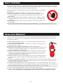 5
5
-
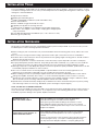 6
6
-
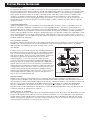 7
7
-
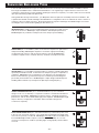 8
8
-
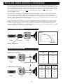 9
9
-
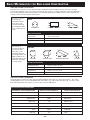 10
10
-
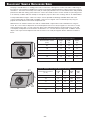 11
11
-
 12
12
-
 13
13
-
 14
14
-
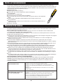 15
15
-
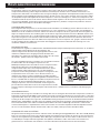 16
16
-
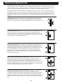 17
17
-
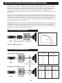 18
18
-
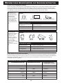 19
19
-
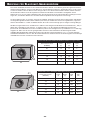 20
20
-
 21
21
-
 22
22
-
 23
23
-
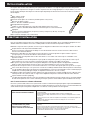 24
24
-
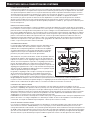 25
25
-
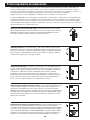 26
26
-
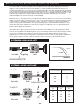 27
27
-
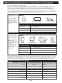 28
28
-
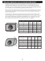 29
29
-
 30
30
-
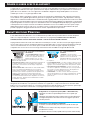 31
31
-
 32
32
-
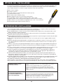 33
33
-
 34
34
-
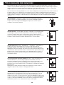 35
35
-
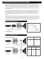 36
36
-
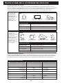 37
37
-
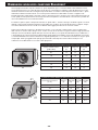 38
38
-
 39
39
-
 40
40
-
 41
41
-
 42
42
-
 43
43
-
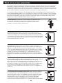 44
44
-
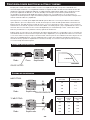 45
45
-
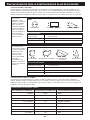 46
46
-
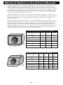 47
47
-
 48
48
-
 49
49
-
 50
50
-
 51
51
-
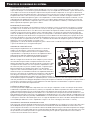 52
52
-
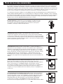 53
53
-
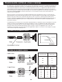 54
54
-
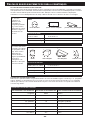 55
55
-
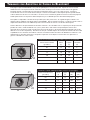 56
56
-
 57
57
-
 58
58
-
 59
59
-
 60
60
-
 61
61
-
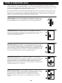 62
62
-
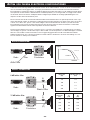 63
63
-
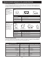 64
64
-
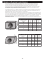 65
65
-
 66
66
-
 67
67
-
 68
68
-
 69
69
-
 70
70
-
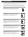 71
71
-
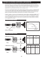 72
72
-
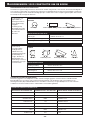 73
73
-
 74
74
-
 75
75
-
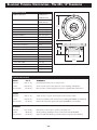 76
76
-
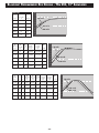 77
77
-
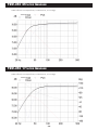 78
78
-
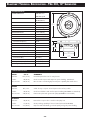 79
79
-
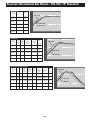 80
80
-
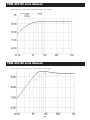 81
81
-
 82
82
-
 83
83
-
 84
84
-
 85
85
-
 86
86


Blaupunkt TSW 250 Bruksanvisning
- Kategori
- Soundbar-högtalare
- Typ
- Bruksanvisning
på andra språk
- italiano: Blaupunkt TSW 250 Manuale del proprietario
- español: Blaupunkt TSW 250 El manual del propietario
- Deutsch: Blaupunkt TSW 250 Bedienungsanleitung
- português: Blaupunkt TSW 250 Manual do proprietário
- français: Blaupunkt TSW 250 Le manuel du propriétaire
- English: Blaupunkt TSW 250 Owner's manual
- Nederlands: Blaupunkt TSW 250 de handleiding
Relaterade papper
Andra dokument
-
Carrera Formula cup Bruksanvisning
-
Celexon 525-W aktywne głośniki 2-drożne Bruksanvisning
-
Yamaha P2075 Bruksanvisning
-
-
Sony XS-HF167 Användarmanual
-
JBL STAGE 1010 Bruksanvisning
-
Infinity REF1000S Bruksanvisning
-
Sony XS-L830 Bruksanvisningar
-
-
Harman Infinity Kappa Serie Bruksanvisning