CTC Union EcoAir 115 Exchange Instruction
- Typ
- Exchange Instruction

CTC EcoAir 115-125 (v.3) - elektronisk avfrostning
Utbytesinstruktion, displaykort
!
Omkoppling av kablar måste utföras av behörig installatör.
Se till att strömmen till anläggningen (faser och nolla) är bruten innan arbetet påbörjas.
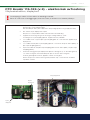
1. Börja med att flytta kablar från gamla displaykortet till det nya.
Börja från G1 och byt kabel för kabel.
När alla kablar på denna plint är bytta finns det fyra lediga positioner högst upp (G17-G20).
2. Gör samma sak på displaykortets F-plint.
Börja från F1 och byt kabel för kabel. Plint F9 kommer då att bli ledig.
3. Koppla bort avfrostningsuret genom att avlägsna samtliga kablar (1-4) från
anslutningar 19-21 på inkopplingsplint X1. Koppla även bort jordkabeln.
4. Lossa kabel 25 från L1 (ej från plint 7) på inkopplingsplint X1 och montera den på plint F9 på
displaykortet.
5. Lossa kabel 106 från plint 21 på inkopplingsplint X1 och montera den på en aktiv nollplint (t ex
plint 19 på inkopplingsplinten).
6. Flytta även kabel 105 från plint 20 på inkopplingsplint X1 till en aktiv nollplint (t ex plint 19 på
inkopplingsplinten).
7. Anslut avfrostningsgivarna på displaykortets plint G17-G18 (givare 1) och G19-G20 (givare 2)
och sedan i förångaren. Använd medföljande clips för att fästa dem i förångaren.
Se till att givarkropparna hamnar, djupledes, i mitten av förångaren.
Givarna ska placeras 250 mm från högerkant (framifrån sett) och 250 mm från underkant
respektive ovankant.
G-plint,
displaykort
F-plint,
displaykort
Displaykort
Ellåda
Inkopplingsplint X1
162 401 58-1 2017-11-28

CTC EcoAir 115-125 (v.3) - electronic defrosting
Exchange instruction, display card
!
The connection of cables must be performed by an authorized installation technician.
Make sure to disconnect the power supply to the unit (phases and ground connections) be-
fore starting to work.
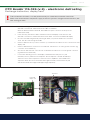
1. Start by transferring the cables from the old display card to the new card.
Start with connection G1 and then transfer all cables of terminal G.
When all cables have been transferred, there will be four spare connections at the top of the
terminal (G17-G20).
2. In the same way, transfer the cables of terminal F from the old display card to the new card.
Start with connection F1 and then transfer the other cables. Connection F9 will then be empty.
3. Disconnect the defrosting device by removing all cables (1-4) from the terminal X1 connections
19-21. Also disconnect the ground cable.
4. Remove cable 25 from L1 (not from connection 7) on terminal X1 and attach it to the connection F9 of the
display card.
5. Remove cable 106 from connection 21 on terminal X1 and attach it to an active ground connection (eg
connection 19 on terminal X1).
6. Also remove cable 105 from connection 20 on terminal X1 and attach it to an active ground connection
(eg terminal 19 on terminal X1).
7. Connect the defrosting sensors to the display card terminal G17-G18 (sensor 1) and
G19-G20 (sensor 2) and then in the evaporator. Use the clips that come with the delivery to
attach the sensors in the evaporator. Position the sensors, depthwise, in the middle of the
evaporator. Attach the sensors 250 mm from the right hand side (seen from the front) and
250mm from the bottom edge and the upper edge respectively.
162 401 58-1 2017-11-28
Terminal G,
display card
Terminal F,
display card
Display card
Connection box
Terminal X1
-
 1
1
-
 2
2


CTC Union EcoAir 115 Exchange Instruction
- Typ
- Exchange Instruction
på andra språk
- English: CTC Union EcoAir 115
