
INSTRUCTION MANUAL
ORIGINAL INSTRUCTIONS/TRANSLATION OF ORIGINAL INSTRUCTIONS
READ AND UNDERSTAND THIS MANUAL PRIOR TO OPERATING OR SERVICING THIS
PRODUCT
Macerator
TA3P-10
IB-401 R03 (03/2016)

Recreational Craft Directive 94/25/EEC
ISO 8846: 1990/Electrical devices - Protection against ignition of surrounding flammable gases
ISO 10133: 1994/Electrical systems - Extra low-voltage DC installations
Electromagnetic Compatibility Directive 89/336/EEC
EN55014: 1993/Radio Disturbance
Made in USA
Garanti 1 år
Warranty 1 year
Garantie 1 Jahr
Garantie 1 an
Garantía 1 año
Garanzia 1 anno
Index - Indice
Svenska .....................................................................................................................................3
English ....................................................................................................................................... 5
Deutsch .....................................................................................................................................7
Français ..................................................................................................................................... 9
Español ................................................................................................................................... 11
Italiano ................................................................................................................................... 13
Fig. ........................................................................................................................................... 15
Besök www.johnson-pump.com för mer information om vår världsomspännande organisation, våra godkännanden, certifieringar och lokala representanter. SPX FLOW,
Inc. förbehåller sig rätten att ändra design och material utan föregående avisering. Designelement, konstruktionsmaterial och dimensioner som beskrivs i denna bulletin
gäller endast som information och skall alltid bekräftas skriftligt för att vara gällande.
For more information about our worldwide locations, approvals, certifications, and local representatives, please visit www.johnson-pump.com. SPX FLOW, Inc. reserves
the right to incorporate our latest design and material changes without notice or obligation. Design features, materials of construction and dimensional data, as descri-
bed in this bulletin, are provided for your information only and should not be relied upon unless confirmed in writing.
Für weitere Informationen über unsere weltweiten Standorte, Zulassungen, Zertifizierungen und unsere Vertreter vor Ort, besuchen Sie bitte unsere Webseite:
www.johnson-pump.com. Die SPX FLOW, Inc. behält sich das Recht vor, die neuesten Konstruktions- und Werkstoffänderungen ohne vorherige Ankündigung und
ohne Verpflichtung hierzu einfließen zu lassen. Konstruktive Ausgestaltungen, Werkstoffe sowie Maßangaben, wie sie in dieser Mitteilung beschrieben sind, sind nur
zur Information. Alle Angaben sind unverbindlich, es sei denn, sie wurden schriftlich bestätigt.
Pour plus d’information sur nos succursales internationales, nos approbations, nos certifications et nos représentants locaux, veuillez consulter notre site Internet au
www.johnson-pump.com. SPX FLOW, Inc. se réserve le droit d’incorporer nos plus récents concepts ainsi que tout autre modification importante sans préavis ou obli-
gation. Les éléments décoratifs, matériaux de construction et les données dimensionnelles, tels qu’énoncés dans ce communiqué, sont fournis pour votre information
seulement et ne doivent pas être considérés comme officiels à moins d’avis contraire par écrit.
Para más información sobre nuestras oficinas a nivel mundial, aprobaciones, certificaciones y representantes locales, por favor visite www.johnson-pump.com. SPX
FLOW, Inc. se reserva el derecho de incorporar nuestro diseño más reciente y cambios materiales sin necesidad de notificación previa u obligación de ningún tipo.
Características de diseño, materiales de construcción y dimensiones, tal y como están descritas en este boletín, son proporcionadas sólo con fines informativos y no
deben ser usados como referencia a menos que sean confirmados por escrito.
Per ottenere maggiori informazioni sulle nostre sedi nel mondo, autorizzazioni, certificazioni, e rappresentanti locali, potete visitare il sito www.johnson-pump.com.
La SPX FLOW, Inc. si riserva il diritto di apportare cambiamenti ai propri design e materiali senza preavviso o vincolo. Le caratteristiche del design, i materiali di
costruzione e i dati dimensionali, così come descritti nel presente bollettino, sono forniti solo per vostra informazione e non saranno oggetto di obbligazione salvo
autorizzazione confermata per iscritto.

3
Översättning av originalinstruktionerna
> Svenska
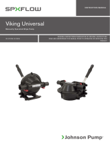
Maceratorpump
Den perfekta toalettpumpen för
båtar och husvagnar
SPX FLOW Johnson Pump toalettpump TA3P10-19
tar hand om toalettavfallet. En roterande kniv sönder-
delar avfallet innan det pumpas ut genom avlopps-
slangen. Pump kan anslutas direkt till WC-utloppet
eller septiktanken.
Obs! Endast oblekt toalettpapper får användas.
Pumpen får ej köras torr. Får ej användas för konti-
nuerlig drift.
Teknisk beskrivning
Pumphus: Fenolplast (PF)
Impeller: Nitril
Kvarnhus: Termoplastisk polyester (PET)
Axel: Rostfritt stål
Tätning: Läpptätning, nitril
Anslutning: Inlopp: 38 mm (1.1/2") slang
eller 1.1/2" rörgänga
Utlopp: 25,4 mm (1") slang
Motor: 0,12kW likströmsmotor,
12/24 V
Motorn är gnistskyddad enligt ISO 8846 (Båtar - El-
komponenter - Skydd mot antändning av omgivande
brännbara gaser)
Modellspecifikation
Typ Art. Nr.
TA3P10-19 12 V 10-24453-04
TA3P10-19 24 V 10-24453-05
Tryck- och kapacitetsdata
(se sid. 15)
Installationsanvisningar
Installation
Pumpen kan monteras i vilket läge som helst
utan effektförlust. Emellertid rekommenderas att
pumphuvudet vänds nedåt vid vertikal montering.
Pumpen måste placeras under septiktank eller
WC-utlopp. Montera motorn så nära kraftkällan
som möjligt för att erhålla full spänning.
Obs! Före installation med elektriskt styrsystem
kontrollera att utrustningen som ska användas
har tillräcklig effekt för motorns strömstyrka. Låg
spänning kan medföra att motorn överhettas.
Elektrisk installation
Pumpen ska installeras i enlighet med ISO 10133
(Båtar - Elektriska system - Klenspänningsinstal-
lationer för likström). Obs! Säkringen ska vara av
gnistskyddad typ. Säkringen utgör ett överström-
skydd och skyddar motorn vid överbelastning och
ev. blockerad rotation.
Felaktig säkringsstorlek kan innebära brandfara.
Om pumpen ansluts med separat jordnings-
kabel ska denna vara gul/grön och anslutas
till motorns fot.
Se kopplingsschema för rätt installation. Negativ
ledare ska vara svart.
Välj kabeldimension efter total kabellängd enligt
tabell.
Obs! Före installation med elektriskt styr-
system kontrollera att utrustningen som ska
användas har tillräcklig effekt för motorns ström-
styrka. Låg spänning kan medföra att motorn
överhettas.

4Översättning av originalinstruktionerna
> Svenska
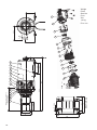
Serviceinstruktioner
(se sid 16-17)
Demontering
1. Tag bort mutter, bricka samt kvarnhuset.
2. Skruva bort kniven. Använd en 7 mm
fast skruvnyckel för att hålla fast axeln
bakom kniven. Vrid kniven moturs.
3. Tag bort slitbrickan, O-ringen och
packningen.
4. Tag ur impellern.
5. Lossa skruv (10).
6. Drag bort pumphuset från motorn.
7. Tag bort skruv (13) och läpptätningen.
Montering
1. Montera läpptätningen i pumphuset och
sätt i skruv (13). Obs! Fjädern i tätningen
ska vara riktad mot impellern.
2. Montera pumphuset på motorn.
3. Skruva i skruv (10).
4. Smörj impellern med vaselin för att
undvika torrkörning och montera med
en roterande rörelse i impellerns
rotationsriktning (medurs).
5. Montera packningen och slitbrickan.*
6. Montera kniven på motoraxeln.
Använd en 7 mm fast skruvnyckel för
att hålla axeln och vrid kniven medurs.
7. Montera O-ringen i kvarnhuset.
8. Montera kvarnhuset, bricka och mutter.*
* Obs! Se till att inloppskanalen på
packningen, slitbrickan och kvarnhuset
kommer i rätt läge på pumphuset.
Avfallshantering/
materialåtervinning
Vid avfallshantering ska produkten lämnas för
destruktion/återvinning enligt gällande lagstift-
ning. Vid tillämpliga fall demonteras och sorteras
produkten i ingående materialfraktioner.
Kopplingsschema
(se sid 18-19)
Kabelarea
(baserat på 3% spänningsfall)
Kabelarea Max kabellängd*
12 V 24 V
1,5 mm2 #16AWG 2,5 m 11,0 m
2,5 mm2 #14AWG 4,2 m 18,3 m
4 mm2 #12AWG 6,8 m 29,3 m
6 mm2 #10AWG 10,1 m
10 mm2 #6AWG 16,9 m
16 mm2 #4AWG 27,0 m
* Kabellängden är det totala avståndet från
batteriet till pumpen och tillbaka till batteriet.
Torrkörning
Kör inte pumpen torr mer än högst 30 sekunder.
Torrkörning bränner upp impellern och skadar
tätningarna.
Varning
Pumpa inte bensin, lösningsmedel, thinner eller
andra lättantändliga vätskor. Om korrosiva vätskor
måste pumpas, skölj pumpen med vatten efter
varje användning.
Temperatur
Max omgivningstemeratur +60˚C.
Pumpen kan ej köras kontinuerligt.
Motorn har ett termiskt överbelastningskydd som
skyddar motorn från överhettning. Skyddet åter-
ställs automatiskt då motorn svalnat.
Minusgrader
Glykol kan användas som frostskyddsmedel men
använd inte petroleumprodukter.
Packning
Använd standardpackning. En tjockare packning
minskar sugförmågan. En tunnare orsakar att
impellern kärvar.

5
Original instructions
> English
Macerator Pump
Installation recommendations
Installation
Pump may be mounted in any position with-out
loss of efficiency; however, it is suggested that
the pump head be down if vertical mounting is
desired. The pump must be installed below the
holding tank or bowl discharge outlet. Mount
motor as close as possible to power source to
obtain full voltage.
Note: Before installation with electrical control
systems, check that equipment to be used is of
sufficient rated capacity to accept ampere draw of
motor. Low voltage will cause motor to overheat.
Electrical installation
The pump must be installed according to
ISO 10133 (Small craft - Electrical system - Extra
low voltage DC installation for continuous cur-
rent). Note: The fuse must be ignition protected.
The fuse works as over-current protection, and
protects the motor from overloading and rotation.
Incorrect fuse size may cause fire.
If the pump is connected with separate earth lead,
this should be yellow/green and connected to the
motor base.
See the wiring scheme for correct installation.
Negative wire must be black.
Choose wire size in accordance with total
wire length (see table).
Note: Before installation with electrical control
systems, check that equipment to be used is of
sufficient rated capacity to accept ampere draw of
motor. Low voltage will cause motor to overheat.
The perfect disposer for the
lavatory unit in boats and
recreational vehicles
The SPX FLOW Johnson Pump macerator pump
TA3P10-19 takes care of toilet waste.
A rotary cutter shreds waste before it is pumped out
through the discharge hose.
The pump can be connected directly to the bowl
discharge outlet or holding tank.
Note: Use unbleached lavatory paper only. Do not
run pump dry. Must not be used for continuous duty.
Design features
Body: Phenol plastic (PF)
Impeller: Nitrile
Housing: Thermoplastic polyester
(PET)
Shaft: Stainless steel
Seal: Lip seal, nitrile
Connection: Inlet: 38 mm (1.1/2") hose,
1.1/2" BSP thread or
1.1/2"-11.1/2" NPTF thread
Outlet: 25,4 mm (1") hose.
Motor: 0,12 kW, 12/24 V DC
The motor is ignition protected according to ISO
8846 (Small craft - Electrical devices - Protection
against ignition of surrounding flammable gases).
Type designation
Type Part No.
TA3P10-19 12 V 10-24453-04
TA3P10-19 24 V 10-24453-05
Pressure and capacity data
(see page 15)

6Original instructions
> English
Service instructions
(see page 16-17)
Disassembly
1. Remove nut, washer and housing.
2. Remove cutter. Use a 7 mm open-ended
spanner to hold shaft behind cutter.
Turn cutter anti-clockwise.
3. Remove the wear plate, the O-ring and
the gasket.
4. Withdraw impeller.
5. Remove screw (10) .
6. Separate body from motor.
7. Remove screw (13) and lip seal.
Assembly
1. Fit lip seal and screw (13) in the body.
Note! The spring of the seal must face
towards the impeller.
2. Fit body to motor.
3. Fit screw (10).
4. Lubricate the impeller with vaseline to
avoid dry running and fit it with a
rotating movement in the intended
direction of the impeller rotation
(clockwise).
5. Fit the gasket and wear plate.*
6. Mount cutter on motor shaft. Use a 7 mm
open-ended spanner to hold shaft and
turn cutter clockwise.
7. Mount the O-ring in the housing.
8. Mount housing, washer and nut.*
* Note! Check that the inlet passage of the
gasket, wear plate and housing are seated
properly on the body.
Waste handling
material recycling
At the products end of life, please dispose of
the product according to applicable law. Where
applicable, please disassemble the product and
recycle the parts material.
Wiring scheme
(see page 18- 19)
Wiring table
(based on 3 % voltage drop)
Wire Max wire length*
size 12 V 24 V
1,5 mm2 #16AWG 2,5 m 11,0 m
2,5 mm2 #14AWG 4,2 m 18,3 m
4 mm2 #12AWG 6,8 m 29,3 m
6 mm2 #10AWG 10,1 m
10 mm2 #6AWG 16,9 m
16 mm2 #4AWG 27,0 m
* The wire length is the total distance from the
battery to the pump and back to the battery.
Dry running
Do not run dry for more than 30 seconds. Lack of
liquid will burn the impeller and damage the seals.
Caution
Do not pump gasoline, solvents, thinners, highly
concentrated or organic acids. If corrosive fluids
must be handled, pump life will be prolonged if
flushed with water after each use or after each
work day.
Temperature
Max ambient temperature + 60°C.
The pump can not be run continuously.
The motor is equipped with built in thermal
protection to prevent the motor from overheating.
The protection is automatically restored when the
motor is cooled.
Freezing weather
Glycol based anti-freezes can be used but do not
use petroleum based anti-freeze compounds.
Gasket
Use standard gasket. A thicker gasket will reduce
priming ability. A thinner gasket will cause impeller
to bind.

7
Übersetzung der Original-Betriebanleitungen
> Deutsch
Fäkalienpumpe
Die perfekte Lösung für die
Abwasserbeseitigung von Toiletten
an Bord oder in Wohnwagen
Die SPX FLOW Johnson Pump TA3P10-19 ist für die
Entsorgung von Fäkalien konstruiert. Ein Schneide-
messer zerkleinert die Fäkalien,
bevor sie abgepumpt werden. Die Pumpe
kann direkt an den Toiletten-Abfluß oder an den
Fäkalientank angeschlossen werden.
Vermerk: Nur ungebleichtes Toiletten-papier (kein
Tissue) verwenden. Die Pumpe darf nicht trocken-
laufen. und nicht für den Dauerbetrieb eingesetzt
werden.
Technische Daten
Pumpen-
gehäuse: Phenolplast (PF)
Impeller: Nitril
Gehäuse: Thermoplastisches
Polyester (PET)
Welle: Rostfreier Stahl
Dichtung: Lippendichtung Nitril
Anschluß: Einlaß: 38 mm (1.1/2")
Schlauch oder 1.1/2" BSP
Auslaß: 25,4 mm (1")
Schlauch
Motor: 0,12kW, 12/24 V GS
Der Elektromotor ist nach ISO 8846 funkenge-
schützt (Elektrische Geräte für
kleine Boote - Funkenschutz)
Modell-Varianten
Typ Artikel Nr.
TA3P10-19 12 V 10-24453-04
TA3P10-19 24 V 10-24453-05
Druck- und Leistungsdaten
(Siehe Seite 15)
Betriebsanleitungen
Montage
Die Pumpe kann in jeder Lage ohne Beein-trächti-
gung der Leistung eingebaut werden.
Es wird jedoch bei stehender Montage
empfohlen, die Pumpe mit Pumpenkopf
nach unten zu montieren. Die Pumpe muß
unter den Abfluß oder dem Fäkalientank
intsalliert werden. Um Spannungsverluste zu
vermeiden, sollte die Pumpe möglichst nahe
an der Batterie installiert werden. Anmerkung: Bei
der Installationen mit elektrischem Kontroll-/Steu-
ersystem ist sicherzustellen, daß die Pumpenmo-
tor aus-reichend mit Strom versogt wird. Bei zu
niedriger Spannung können Überhirzungs-
schäden am Motor aufreten
Elektrische Installation
Die Pumpe muß nach den Bestimmungen
ISO 10133 (Elektrisches System für kleine
Boote/Gleichstrom-Installation für Dauer-
strom) installiert werden. Vermerk: Der
Sich.-Automat muß funkengeschützt sein. Diese
Sicherung arbeite wie ein ÜberlastSchutzautomat
und schützt den Motor vor Überlast und zu
hoher Drehzahl. Falsche Sicherungen können
einen Brand verursachen.
Wenn die Pumpe mit einem separaten Masse-
Kabel angeschlossen wird, sollte dieses ein
gelb/grünes Kabel sein und mit der Motorbasis
verbunden werden.
Beachten Sie bitte den Schaltplan. Das Minus-
Kabel muß schwarz sein. Die kabelstärke
sollte entsprechend der Kabel-Gesamtlänge
ausgewählt werden (siehe Tabelle).
Vermerk: Bevor Sie elektrische Kontroll-
systeme installieren, prüfen Sie, ob das Zu-
behör ausreichend dimensioniert ist, um die
Leistungsaufnahme des Motor zu gewähr-
leisten. Niedrige Spannung verursaucht Über-
hitzungen des Motors.

8Übersetzung der Original-Betriebanleitungen
> Deutsch
Wartungsanleitungen
(siehe Seite 16-17)
Demontage
1. Mutter losschrauben, Unterlegscheibe und
Gehäuse entfernen.
2. Schneidemesser entfernen. Die Welle hinter
dem Schneidemesser mit einem 7 mm
Schraubenschlüssel halten. Das
Schneidemesser entgegen dem Uhr-
zeigersinn losschrauben.
3. Verschleißscheibe, O-Ring und Dichtung
entfernen.
4. Impeller herausziehen.
5. Schrauben entfernen (10).
6. Das Pumpengehäuse vom Motor trennen.
7. Schrauben (13) und Lippendichtung
entfernen.
Montage
1. Die neue Lippendichtung und Schrauben
(13) im Pumpengehäuse einführen.
Anmerkung: Die Feder der Dichtung
muß in Richtung Impeller weisen.
2. Pumpengehäuse und Motor zusammen-
setzen.
3. Schrauben (10) anziehen.
4. Der Impeller mit Vaselin schmieren
und so einsetzen, daß die Drehbe-
wegung der vorgesehenen Pumpen-
drehbewegung entspricht (im Uhrzeigersinn
drehen).
5. Dichtung und Verschleißscheibe einsetzen.*
6. Schneidemesser auf der Welle schrauben.
Dabei die Welle mit einem 7 mm
Schraubenschlüssel festhalten und das
Schneidemesser im Uhrzeigersinn
festziehen.
7. Den O-Ring in Gehäuse einsetzen.
8. Das Gehäuse, die Unterlegscheibe und die
Mutter montieren.*
* Anmerkung: Überprüfen Sie, daß der
Einlaßkanal der Dichtung, der
Verschleißscheibe und des Gehäuses gut
ausgerichtet sind.
Entsorgung/Recycling
Nach Lebensdauerende entsorgen Sie die Pumpe
nach den örtlichen Vorschriften.
Nach Möglichkeit demontieren Sie Teile der Pum-
pe um sie dem Recycling-Process zuzuführen.
Schaltplan
(siehe Seite 18-19)
Tabelle Kabelanschlüsse
(Basierend auf 3% Spannungsverlust)
Kabel- Max Kabellänge*
querschnitt 12 V 24 V
1,5 mm2 #16AWG 2,5 m 11,0 m
2,5 mm2 #14AWG 4,2 m 18,3 m
4 mm2 #12AWG 6,8 m 29,3 m
6 mm2 #10AWG 10,1 m
10 mm2 #6AWG 16,9 m
16 mm2 #4AWG 27,0 m
* Die Kabellänge ist die komplette Länge von der
Batterie zur Pumpe und zurück zur Batterie
Trockenlaufen
Nicht länger als 30 Sekunden trockenlaufen las-
sen, da sonst der Impeller und die Dich-tungen
durch Überhitzen beschädigt werden.
Achtung
Kein Benzin, keine Lösungsmittel, Verdünnungs-
mittel, organische oder hochkonzentrierte Säuren
pumpen. Wenn ätzende Flüssigkeiten gepumpt
werden müssen, kann die Standzeit der Pumpe
dadurch verlängert werden, daß sie nach
dem Gebrauch oder mindestens einmal pro Tag
mit Wasser durchgespült wird.
Temperatur
Max. Umgebungs-Temperatur +60ºC.
Die Pumpe ist nicht für Dauerlauf geeignet.
Der Motor hat einen thermischen Überlastungs-
schutz. Wenn die Überlastungstemperatur wieder
zum normalen Niveau abgesunken ist, schaltet der
Überlastschutz automatisch wieder ab. Der Motor
kan wieder gestartet werden.
Bei Frostgefahr
Bei Frostgefarhe können Ethylenglykol-basierte
Frostschutzmittel verwendet werden. Frostschutz-
mittel auf Mineralöl-basis dürfen keine Verwen-
dung finden.
Dichtung
Verwenden Sie nur Original-Dichtungen. Stärkere
Dichtungen vermindern das Ansaugvermögen,
dünnere Dichtungen verursachen ein Blockieren
des Impellers.

9
Traduction du manuel d'instruction d'origine
> Français
Instructions d’installation
Installation
La pompe peut être montée dans toutes les
positions sans pour autant affecter son efficacité;
cependant, nous recommandons d’installer la
pompe la tête en bas si une fixation verticale est
désirée. La pompe doit être installée en dessous
de la cuve ou de la sortie d'écoulements de la
cuvette. Monter le moteur aussi près que possible
de la source d’alimentation afin d’obtenir une
pleine tension.
Important: Avant toute installation avec un
système de commande électrique, vérifier
que le matériel qui va être utilisé, peut supporter
le courant demandé par le moteur. Une basse
tension entraînera une surchauffe du moteur.
Installation électrique
La pompe doit être installée suivant les recom-
mandations ISO 10133 (Petits bateaux, système
électrique, installation à courant continu de très
basse tension).
Nota: Le fusible doit être ”anti-deflagrant”. Ce
fusible apporte une protection contre la surinten-
sité, et protège le moteur en cas de surcharge en
rotation.
Un fusible de calibre incorrect peut provoquer in
incendie.
Choisir la section du fil en fontion de sa longueur
totale (voir tableau).
Nota: Avant toute installation avec un système de
commande électrique, vérifier que le matériel qui
va être utilisé, peut supporter le courant demandé
par le moteur. Un basse tension entraînera un
surchauffe du moteur.
Pompe macératice
Le broyeur parfait pour les
toilettes dans les bateaux et les
véhicles de loisir
La pompe SPX FLOW Johnson Pump TA3P10-19
traite les eaux usées de vos toilettes. Un cou-
teau circulaire déchiquette les déchets qui sont
ensuite pompés vers l’extérieur à travers un tuyau
d’écoulement. La MP 1000 peut être connectée
directement à la sortie d’écoulement de la cuvette
ou à la cuve.
Important: Utiliser uniquement du papier de
toilette non blanchi. Ne pas faire fonctionner la
pompe à vide.
Ne pas utiliser en service continu.
Caractéristiques techniques
Corps: Phénoplaste (PF)
Rotor: Nitrile
Boîtier: Polyester thermoplastique
(PET)
Arbre: Acier inoxydable
Joint: Joint à lèvre, Nitrile
Moteur: 12/24 V CC
Raccords: Arrivée: tuyau de 38 mm
(1.1/2") ou 1.1/2" BSP
Sortie: tuyau de 25,4 mm (1")
Moteur: 0,12 kW, 12/24 V CC
Le moteur est ”antidéflagrant” suivant la norme
ISO 8846 (Equipement électrique de petits ba-
teaux dans un environnement de gaz inflammable)
Spécifications du modèle
Modèle Référence
TA3P10-19 12 V 10-24453-04
TA3P10-19 24 V 10-24453-05
Caractéristiques de pression et
débit
(voir page 15)

10 Traduction du manuel d'instruction d'origine
> Français
Schéma électrique
(voir page 18-19)
Section des fils
(basé sur une chute den tension de 3%)
Section Longueur maxi*
12 V 24 V
1,5 mm2 #16AWG 2,5 m 11,0 m
2,5 mm2 #14AWG 4,2 m 18,3 m
4 mm2 #12AWG 6,8 m 29,3 m
6 mm2 #10AWG 10,1 m
10 mm2 #6AWG 16,9 m
16 mm2 #4AWG 27,0 m
* La longueur totale correspond à la distance de
la batterie à la pompe et du retour de la pompe à
la batterie.
Fonctionnement à vide
Ne pas faire fonctionner la pompe à vide plus que
30 secondes. Une absence de liquide brûlera le
rotor et endommagera les joints.
Attention
Ne pas pomper d’essence. de solvants, de
diluants, d’acides organique ou très concentrés.
Dans le cas d´un fonction-nement avec des
liquides corrosifs un rinçage à l´eau après chaque
utilisation ou après chaque journée de travail
prolongera sa durée de vie.
Temperature
Températures ambiante: maxi +60ºC
La pompe ne peut pas fonctionner en utilisation
continue.
Le moteur est équipé d’une protection thermique
intégrée afin de le protéger contre les surchauf-
fes. La protection est automatiquement réarmée
dès que le moteur a refroidi.
Températures ambiantes en
dessous de 0ºC
Des antigels à base de glycol peuvent être utili-
sés. Ne pas utiliser d’antigel à base de pétrole.
Joint
Utiliser un joint standard. Un joint plus épais
réduirait le pouvoir de succion. Un joint plus fin
entraînerait le grippage du rotor.
Instructions d’entretien
(voir page 16-17)
Démontage
1. Retirer l'ecrou, la rondelle et le boîtier.
2. Retirer le couteau. Utiliser une clé plate
de 7 mm pour tenir l’arbre à l’arrière du
couteau et tourner ce dernier dans le sens
contraire des aiguilles d’une montre.
3. Retirer la plaque d’usure, le joint torique
et le joint d’étanchéité.
4. Sortir le rotor.
5. Enlever la vis (10).
6. Séparer le moteur du corps.
7. Enlever la vis (13) et le joint à lèvre.
Montage
1. Ajuster le joint à lèvre et la vis (13) sur le
corps. Important: le ressort du joint doit
faire face au rotor.
2. Ajuster le corps et le moteur.
3. Mettre la vis (10).
4. Lubrifier le rotor avec de la vaseline afin
d’éviter le fonctionnement à vide et
l’ajuster à l’aide d’un mouvement
tournant allant dans la direction voulue
de sa rotation (dans le sens des aiguilles
d’une montre).
5. Ajuster le joint et la plaque d’usure.*
6. Monter le couteau sur l’arbre moteur.
Utiliser une clé plate de 7 mm pour tenir
l’arbre et, tourner le couteau dans le sens
des aiguilles d’une montre.
7. Monter le joint torique sur le boîtier.
8. Monter le boîtier, la rondelle, et l’ecrou.*
* Important: Vérifier que le passage
d’arrivée du joint, de la plaque d’usure et
du boîtier soient montés correctement sur
le corps.
Gestion des déchets/recyclage
des matériaux
Lorsque le matériel arrivera en fin de vie, veuillez
le mettre au rebut en fonction des lois applica-
bles. Lorsque c'est possible, veuillez démonter le
matériel et recycler les pièces pouvant l'être

11
Traducción de instrucciones originales
> Español
Bomba trituradora
La bomba ideal para evacuar
los residuos de inodoros en
embarcaciones y caravanas
La trituradora TA3P10-19 de SPX Johnson
Pump se encarga de los desechos del
retrete. Una cuchilla giratoria deshace los resíduos
entes de evacuarlos. La TA3P10-19 puede conec-
tarse al racord de salida o al depósito séptico.
Aviso: Emplear solamente papel higiénico.
No debe funcionar en seco. No utilizar de forma
contínua.
Características técnicas
Cuerpo: Fenol plástico (PF)
Propulsor: Nitrilo
Bastidor: Termoplástico de poliéster
(PET)
Eje: Acero inoxidable
Junta: Labial
Empalmes: Entrada 38 mm (1.1/2")
ó 1.1/2" BSP
Salida 25,4 mm (1")
Motor: 0,12 kW, 12/24 V CC
Motor con protección de encendido según
ISO 8846 (Pequeñas embarcaciones -
Artículos eléctricos - Antideflagantes en ambientes
de gases inflamables)
Modelo
Tipo Pieza No
TA3P10-19 12 V 10-24453-04
TA3P10-19 24 V 10-24453-05
Presiones y caudales
(ver página 15)
Instrucciones de instalación
Instalación
La bomba puede montarse en cualquier
posición sin que su eficacia se vea afectada,
pero si se instala en posición vertical, se reco-
mienda poner el cabezal en la posición inferior.
La bomba debe ser instalada debajo del tanque
acumulador a la salida del desagüe. Montar el
motor lo más cerca que sea posible de la fuente
de alimentación para aprovechar al máximo la
tensión.
Nota: Antes de instalar sistemas eléctricos de
control, comprobar que el equipo a utilizar
tiene la capacidad nominal necesaria para aco-
modar el amperaje del motor. Una tensión baja
provoca el recalentamiento del motor.
Instalación eléctrica
La bomba debe instalarse según ISO 10133
(Pequeñas embarcaciones - Equipos
eléctricos - Instalciones de bajo voltaje en
corriente contínua). Nota: El fusible deber
ser antideflagante. El fusible protege una excesiva
intensidad y evita una sobrecarga del motor. Un
fusible incorrecto puede provocar fuego. Elegir
el cable del grosor adecuado al largo de cada
instalación.
Nota: Antes de instal sistemas eléctricos de
control, comprobar que el equipo a utilizar
tiene la capacidad nominal necesaria para aco-
modar el amperaje del motor. Una tensión baja
provoca el recalentamiento del motor.

12 Traducción de instrucciones originales
> Español
Instrucciones de mantenimiento
(ver página 16-17)
Desmontaje
1. Quitar tuerca, arandela y bastidor.
2. Separar la cuchilla. Emplear una llave de
7 mm para sujetar el eje por detrás de la
cuchilla. Girar a izquierdas.
3. Sacar la placa de defensa, la junta tórica y
la junta.
4. Quitar el propulsor.
5. Separar tornillos (10).
6. Separar el alojamiento del motor.
7. Quitar tornillos (13) y junta de labio.
Montaje
1. Instalar junta de labio y tornillos (13) en
el bastidor. Aviso: El muelle de la junta
debe mirar al propulsor.
2. Instalar el bastidor del motor.
3. Montar tornillos (10).
4. Lubricar el propulsor con vaselina para
evitar que funcione en seco y montarlo
con un movimiento giratorio en el mismo
sentido que la rotación del propulsor (a
derechas).
5. Instalar la junta y placa de defensa.*
6. Montar la cuchilla en el eje del motor.
Emplear una llave de 7 mm para sujetar
el eje y hacer girar a derechas.
7. Montar la junta tórica en el bastidor.
8. Montar alojamiento, arandela y tuerca.*
* Aviso: Comprobar que el pasaje de
entrada de la junta, plancha de
defensa y alojamiento están bien
montados en el bastidor.
Desguace/Reciclado
Al final de la vida del equipo disponga de este
de acuerdo a la ley. Donde sea de aplicación
desmonte el equipo y recicle los diferentes
materiales.
Esquema eléctrico
(ver página 18-19)
Tabla de cables
(basada en caida de voltaje 3%)
Sección Largo max. del cable*
cable 12 V 24 V
1,5 mm2 #16AWG 2,5 m 11,0 m
2,5 mm2 #14AWG 4,2 m 18,3 m
4 mm2 #12AWG 6,8 m 29,3 m
6 mm2 #10AWG 10,1 m
10 mm2 #6AWG 16,9 m
16 mm2 #4AWG 27,0 m
* El largo del cable, es la distancia totale desde la
bateria a la bomba y regreso a la bateria.
Funcionamiento en seco
No debe funcionar en seco más de 30 segundos.
Las juntas y el impulsor se queman por falta de
líquido.
Advertencia
No bombear gasolina, disolventes y diluyentes de
concentración elevada o ácidos orgánicos. Si es
necesario bombear fluidos corrosivos, se alarga
la vida de la bomba, bombeando agua potable
después de cada uso o de cada día.
Temperatura
Máxima temeratura ambiente +60ºC.
La bomba no debe funcionar continuamente.
El motor tiene un dispositivo para evitar el sobre-
calentamiento. Su funcionamiento se restablece
automáticamente cuando el motor se enfria.
Heladas
Se pueden emplear anticongelantes a base
de glicol, pero no anticongelantes a base de
petróleo.
Junta
Usar juntas estandar. Una junta más gruesa
reduce la capacidad de succión. Con una junta
delgada, el impulsor se agarrota.

13
Traduzione delle istruzioni originali
> Italiano
Pompa di macerazione
Il perfetto maceratore di rifiuti per
la toilette in imbarcazioni e veicoli
di ricreazione
Il Johnson Pump TA3P10-19 si prende cura del
liquame della toilette. Una taglierina rotante taglia
gli scarti prima che questi siano pompati fuori
attraverso il tubo di scarico. Il modello TA3P10-19
può essere collegato direttamente alla mandata di
scarico della tazza o al serbatoio di tenuta.
Nota: Usare soltanto carta igienica non clorinata.
Non far operare la pompa a secco. Non impiegare
in servizio continuo.
Caratteristiche tecniche
Corpo: Plastica al Fenolo (PF)
Girante: Nitrile
Alloggiamento: Poliestere termoplastico
(PET)
Albero: Acciaio inossidabile
Guarnizione: Guarnizione a becco,
nitrile
Motore: 0,12 kW, 12/24 V DC
Collegamento: Tubo di aspirazione
38 mm (1.1/2") o
1.1/2" BSP
Tubo di mandata
25,4 mm (1")
L’accensione del motore è conforme alla norma
ISO 8846 (piccolo impianti - dispositivi elettrici),
dotata di protezione anticendio provocato da gas
o liquidi inflammabili.
Specifica del tipo
Tipo Art. No.
TA3P10-19 12 V 10-24453-04
TA3P10-19 24 V 10-24453-05
Specifiche di pressione e portata
(vedi página 15)
Istruzioni di funzionamento
Installazione
La pompa può essere montata in qualsiasi posi-
zione senza perdita di efficienza;
comunque, si suggerisce di posizionare la
pompa con la testa verso il basso se si
desidera il montaggio verticale. La pompa
deve essere installata inferiormente al
serbatoio di tenuta o alla mandata di scarico
della tazza. Montare il motore il più vicino possi-
bile alla fonte di alimentazione per ottenere il mas-
simo del voltaggio. Nota: Prima dell’installazione
con i sistemi di controllo elettrici, controllare che
l’attrezzatura da usare sia di capacità sufficiente
da accettare il consumo di ampere del motore.
Non usare cavi elettrici di sezione inferiore a
quella suggerita. Il basso voltaggio può causare il
surriscaldamento del motore.
Installazione elettrica
La pompa è construita secondo le norme
ISO 10133 (funzionamento in corrente
continua per piccolo circuiti).
Nota! Si consiglia di proteggere l’accensione
con fusibile. Questo fusibile protegge il motore
della pompa in caso si verificassero violenti
cambiamenti di tensione. Un fusibile
diverso potrebbe causare incendi. Scegliete la
grandezza del cavo tenendo conto della lung-
hezza totale del cavo (vedere tabella) La
pompa non può lavorare senza interruzione.
Nota: Prima dell’installazione con i sistemi di
controllo elettrici, controllare che l’attrezza-
tura da usare sia di capacità sufficiente da
accettare il consumo di ampere del motore.
Non usare cavi elettrici di sezione inferiore a
quella suggerita. Il basso voltaggio può
causare il surriscaldamento del motore.

14 Traduzione delle istruzioni originali
> Italiano
Istruzioni per la manutenzione
(vedi página 16-17)
Smontaggio
1. Rimuovere il bullone, la rondella e
l’alloggiamento.
2. Rimuovere la taglierina. Usare una chiave
aperta da 7 mm per tenere l’albero dietro
alla taglierina. Girare la taglierina in senso
antiorario.
3. Rimouvere la piastra di usura, l’O-ring e
la guarnizione.
4. Ritirare la girante.
5. Rimuovere le viti (10).
6. Separare il corpo dal motore.
7. Rimuovere la vite (13) e la guarnizione a
becco.
Montaggio
1. Sistemare la guarnizione a becco e la vite
(13) nel corpo. Nota! La molla della
guarnizione deve guardare verso la
girante.
2. Sistemare il corpo al motore.
3. Sistemare la vite (10).
4. Lubrificare la girante con vaselina per
evitare funzionamento a secco e sistemarlo
con un movimento rotatorio nella intesa
direzione di rotazione del girante (in senso
orario).
5. Sistemare la guarnizione e la piastra di
usura.*
6. Montare la taglierina sull'albero del
motore. Usare una chiave aperta da 7 mm
per tenere l’albero e girare la taglierina in
senso orario.
7. Montare l’O-ring sulla cassa.
8. Montare l’alloggiamento, la rondella e il
dado.*
* Nota! Controllare che il passaggio
di aspirazione delle guarnizione,
piastra di usura e alloggiamento
siano correttamente posizionate
sul corpo.
Gestione dei rifiuti/
riciclaggio dei materiali
Al termine della vita del prodotto si prega di
smaltire il prodotto secondo le leggi in vigore
per queste operazioni. Quando possibile, si
raccomanda di smontare il prodotto e riciclare i
materiali dei componenti.
Schema elettrico
(vedi página 18-19)
Tabella inform. per la scelta sezione cavi
(Variazione = 3%V)
Sezione Max lunghezza del filo*
del filo 12 V 24 V
1,5 mm2 #16AWG 2,5 m 11,0 m
2,5 mm2 #14AWG 4,2 m 18,3 m
4 mm2 #12AWG 6,8 m 29,3 m
6 mm2 #10AWG 10,1 m
10 mm2 #6AWG 16,9 m
16 mm2 #4AWG 27,0 m
* La lunghezza del filo si trova calcolando la
dixtanza dalla batteria alla pompa e ritorno
Funzionamento a secco
Non far funzionare a secco per più di 30 secondi.
La mancanza di liquido brucerà la girante e dan-
neggerà le guarnizioni.
Cautela
Non pompare benzina, solventi, diluenti, acidi al-
tamente concentrati od organici. Se è necessario
trattare fluidi corrosivi, la durata della pompa potrà
essere prolungata sciacquandola con acqua dopo
ciasun uso o dopo ogni giorno di lavoro.
Temperatura
Tempertura ambiente max +60ºC.
La pompa non può funzionare in modo continuo.
Il motore è dotato di protezione termica contro
il surriscaldamento. La protezione termica si
ripristina automaticamente non appena il motore
si raffredda.
Condizioni atmosferiche di gelo
Si possono usare liquidi anti-gelo a base di gli-
cole, ma non si possono usare composti anti-gelo
a base di petrolio.
Guarnizione
Usare guarnizione standard. Una guarnizione più
spessa ridurrebbe la capacità di adescamento.
Una guarnizione più sottile potrebbe causare il
frenamento della girante.

15
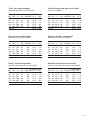
Tryck- och kapacitetsdata
(baserade på vatten vid 20°C/68ºF)
Strömförbrukn.
Bar kPa ft l/min USGPM 12 V 24 V
0,2 20 6,7 37 10,0 13 A 7 A
0,4 40 13,4 34 9,0 14 A 7 A
0,6 60 20,1 30 8,0 14 A 7 A
0,8 80 26,8 28 7,5 15 A 8 A
1,0 100 33,5 22 6,0 15 A 8 A
Säkring 20 A 12 A
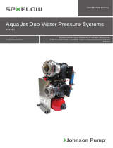
Pressure and capacity data
(based on water at 20°C/68ºF)
Ampere draw
Bar kPa ft l/min USGPM 12 V 24 V
0,2 20 6,7 37 10,0 13 A 7 A
0,4 40 13,4 34 9,0 14 A 7 A
0,6 60 20,1 30 8,0 14 A 7 A
0,8 80 26,8 28 7,5 15 A 8 A
1,0 100 33,5 22 6,0 15 A 8 A
Fuse 20 A 12 A
Druck- und Leistungsdaten
(bei Wassertemperatur von 20°C/68ºF)
Stromaufnahme
Bar kPa ft l/min USGPM 12 V 24 V
0,2 20 6,7 37 10,0 13 A 7 A
0,4 40 13,4 34 9,0 14 A 7 A
0,6 60 20,1 30 8,0 14 A 7 A
0,8 80 26,8 28 7,5 15 A 8 A
1,0 100 33,5 22 6,0 15 A 8 A
Sicherung 20 A 12 A
Caractéristiques de pression et débit
(l'eau à 20°C/68ºF)
Intensité
Bar kPa ft l/min USGPM 12 V 24 V
0,2 20 6,7 37 10,0 13 A 7 A
0,4 40 13,4 34 9,0 14 A 7 A
0,6 60 20,1 30 8,0 14 A 7 A
0,8 80 26,8 28 7,5 15 A 8 A
1,0 100 33,5 22 6,0 15 A 8 A
Fusible 20 A 12 A
Datos de presión y capacidad
(basados en agua a 20°C/68ºF)
Amperaje
Bar kPa ft l/min USGPM 12 V 24 V
0,2 20 6,7 37 10,0 13 A 7 A
0,4 40 13,4 34 9,0 14 A 7 A
0,6 60 20,1 30 8,0 14 A 7 A
0,8 80 26,8 28 7,5 15 A 8 A
1,0 100 33,5 22 6,0 15 A 8 A
Fusible 20 A 12 A
Specifiche di pressione e portata
(basate sulla temp. dell’acqua a 20°C/68ºF)
Amperaggio
Bar kPa ft l/min USGPM 12 V 24 V
0,2 20 6,7 37 10,0 13 A 7 A
0,4 40 13,4 34 9,0 14 A 7 A
0,6 60 20,1 30 8,0 14 A 7 A
0,8 80 26,8 28 7,5 15 A 8 A
1,0 100 33,5 22 6,0 15 A 8 A
Fusibile 20 A 12 A

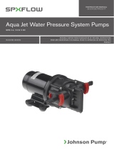
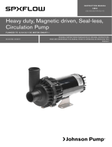
16
AA
SECTION A-A
102
76
7
4
2
9
65
8
12
11
3
13
7
2
12
11
10
6
4
5
8
9
3
42
44,7
Ø25,4
68,3
O38
G
40
256
86 88
51
12,5(12,5)
14
14
178,2 51
10 1
Ø5(4x)
45
111,7Meassure to outlet
Mått till utlopp
1
16 15
Weight
Poids
Gewicht
Peso
Vikt
1,9 kg
Dim. mm

17
Pos Nos No Description Descrizione Descripción
1 1 01-24466-01 Moteur 12V Motore 12V Motor 12V
1 01-24466-02 Moteur 24V Motore 24V Motor 24V
2 1 01-35719-1 Corps Corpo Cuerpo
3 1 01-35275-2 Boîtier Alloggiamento Bastidor
4* 1 09-1052S-9 Rotor Girante Propulsor
5 1 37-3206221 Plaque d'usure Piastra di usura Placa de defen-
sa
6* 1 37-3206217 Joint d'étanchéité Guarnizione Junta
7* 1 05-29-135 Joint à lèvre Guarnizione a becco Junta de labio
8* 1 05-06-583 Joint torique O-ring Junta tórica
9 1 37-3206218 Couteau Taglierina Cuchilla
10 4 05-04-577 Vis Vite Tornillo
11* 3 05-05-511 Ecrou Dado Tuerca
12 3 05-01-520 Rondelle Rondella Arandela
13 3 05-04-643 Vis Vite Tornillo
14 1 05-17-535 Fusible 15A, 12V Fusible 15A, 12V Fusible 15A, 12V
1 05-17-550 Fusible 10A, 24V Fusible 10A, 24V Fusible 10A, 24V
* 1 09-45595 Kit d´entretien Kit di servizio Juego mantenimiento
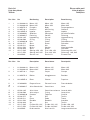
Parts list
Liste des pièces
Teilliste
Pos Nos No Benämning Description Bezeichnung
1 1 01-24466-01 Motor 12V Motor 12V Motor 12V
1 01-24466-02 Motor 24V Motor 24V Motor 24V
2 1 01-35275-2 Pumphus Body Pumpengehäuse
3 1 01-35719-1 Kvarnhus Mill housing Gehäuse
4* 1 09-1052S-9 Impeller Impeller Impeller
5 1 37-3206221 Slitbricka Wear plate Verschleißscheibe
6* 1 37-3206217 Packning Gasket Dichtung
7* 1 05-29-135 Läpptätning Lip seal Lippendichtung
8* 1 05-06-583 O-ring O-ring O-Ring
9 1 37-3206218 Kniv Cutter Schneidemesser
10 4 05-04-577 Skruv Screw Schraube
11* 3 05-05-511 Mutter Nut Mutter
12 3 05-01-520 Bricka Washer Unterlegscheibe
13 3 05-04-643 Skruv Screw Schraube
14 1 05-17-535 Säkring 15A, 12V Fuse 15A, 12V Sicherung 15A, 12V
1 05-17-550 Säkring 10A, 24V Fuse 10A, 24V Sicherung 10A, 24V
* 1 09-45595 Service sats Service kit Erstatzeilsatz
Elenco delle parti
Lista de piezas
Detaljlista

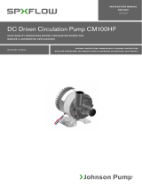
18
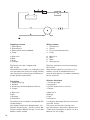
Kopplingsschema
1 Säkringsbox
2 Strömbrytare
3 Säkring (överströmsskyddad)
4 Pump
A Max 0,2 m
B Röd
C Svart
D Grön/gul
Elinstallation ska ske i enlighet med
ISO 10133.
Andra elektriska styrdon, t ex nivåbrytare, tryck-
och vakuumbrytare, reläer och övriga strömbry-
tare ska placeras mellan pump och batteriets
pluspol (på den röda kabeln).
Schaltplan
1 Hauptsicherung
2 Schalter
3 Sicherungs-Automat (Überlast-Schutz)
4 Pumpe
A Max 0,2 m
B Rot
C Schwarz
D Gelb/Grün
Die elektronische Installation muß gemäß ISO
10133 erfolgen.
Alle anderen elektrischen Komponenten, wie
Schalter, Sicherung etc., müssen zwichen der
Pumpe und dem Batterie-Pluspol (+) am roten
Kabel installiert werden.
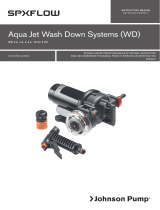
Wiring scheme
1 Terminal fuse
2 Switch
3 Fuse (overload protection)
4 Pump
A Max 0,2 m
B Red
C Black
D Green/yellow
Electrical installation must be according to
ISO 10133.
Other electrical devices, eg switch, circuit
breaker, must be installed between the
pump and the positive (+) lead on the battery
(on the red wire).
Schéma électrique
1 Fusible principal
2 Interrupteur
3 Fusible (protection sur tension)
4 Pompe
A Max 0,2 m
B Rouge
C Noir
D Vert/jaune
L´installation électrique doit être en accord
avec ISO 10133 .
Pour autres accessoires électrique tels
que interrupteurs, disjoncteurs doivent être
installé entre la pompe et le positif (+) de la
batterie (sur le fil rouge).

19
Esquema elétrico
1 Fusible
2 Interruptor
3 Fusible (protección sobrecarga)
4 Bomba
A Max 0,2 m
B Rojo
C Negro
D Verde/amarillo
La installación elétrica debe se según ISO
10133. Los demás dispositivos eléctricos
(interruptor, disyuntor) deben instalarse
entre la bomba y el positivo de la battería
(cable rojo).
Schema elettrico
1 Fusible principal
2 Interruttore
3 Fusible (di protezione sovracarico)
4 Pompa
A Max 0,2 m
B Rosso
C Nero
D Verde/giallo
La pompa è costruita secondo le norme ISO
10133 (funzionamento in corrente continua
per piccolo circuiti). Altre installazioni elett-
riche p.es. interruttori ecc, devono essere
montate tra la pompa e il positivo (+) della
batteria (filo rosso).

SPX FLOW TECHNOLOGY SWEDEN AB
Nastagatan 19, P.O. Box 1436
SE-701 14 Örebro, Sweden
P: +46 (0)19 21 83 00
F: +46 (0)19 27 23 77
E: johnson-pump.marine@spxflow.com
SPX FLOW, Inc. reserves the right to incorporate our latest design and
material changes without notice or obligation. Design features, materials
of construction and dimensionals data, as described in this bulletin, are
provided for your information only and should not be relied upon unless
confirmed in writing.
Please contact your local sales representative for product availability in
your region. For more information visit www.spxflow.com.
ISSUED 03/2016 IB-401/R03
COPYRIGHT ©2016 SPX FLOW, Inc.
Macerator
TA3P-10
-
 1
1
-
 2
2
-
 3
3
-
 4
4
-
 5
5
-
 6
6
-
 7
7
-
 8
8
-
 9
9
-
 10
10
-
 11
11
-
 12
12
-
 13
13
-
 14
14
-
 15
15
-
 16
16
-
 17
17
-
 18
18
-
 19
19
-
 20
20


på andra språk
- italiano: SPX FLOW Macerator Pump Manuale utente
- español: SPX FLOW Macerator Pump Manual de usuario
- Deutsch: SPX FLOW Macerator Pump Benutzerhandbuch
- français: SPX FLOW Macerator Pump Manuel utilisateur
Relaterade papper
-
 SPX FLOW Bilge, Deck Wash and Refueling pump Användarmanual
-
 SPX FLOW Bilge Pump Float Switche Användarguide
-
 SPX FLOW Aqua Jet Användarmanual
-
 SPX FLOW Aqua jet WPS Användarmanual
-
 SPX FLOW Aqua Jet WD Pump Användarmanual
-
 SPX FLOW Vacuum Switch Användarmanual
-
 SPX FLOW Viking Compact Användarmanual
-
 SPX FLOW Viking Universal Användarmanual
-
 SPX FLOW CM90 Användarmanual
-
 SPX FLOW CM100HF Användarmanual


