Sidan laddas...

INSTRUCTION MANUAL
CM100HF
(SE/EN)
ORIGINAL INSTRUCTIONS/TRANSLATION OF ORIGINAL INSTRUCTIONS
READ AND UNDERSTAND THIS MANUAL PRIOR TO OPERATING OR SERVICING THIS PRODUCT
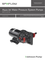
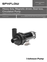
DC Driven Circulation Pump CM100HF
HIGH QUALITY BRUSHLESS MOTOR CIRCULATION PUMPS FOR
MARINE & AUTOMOTIVE APPLICATIONS
IB-308 R03 (10/2018)

Index - Indice
Svenska .................................................................................................................................3
English .................................................................................................................................10
SE: Besök www.spxflow.com för mer information om vår världsomspännande organisation, våra godkännanden,
certifieringar och lokala representanter. SPX FLOW, Inc. förbehåller sig rätten att ändra design och material utan
föregående avisering. Designelement, konstruktionsmaterial och dimensioner som beskrivs i denna bulletin gäller endast
som information och skall alltid bekräftas skriftligt för att vara gällande.
EN: For more information about our worldwide locations, approvals, certifications, and local representatives, please visit
www.spxflow.com. SPX FLOW, Inc. reserves the right to incorporate our latest design and material changes without notice
or obligation. Design features, materials of construction and dimensional data, as described in this bulletin,
are provided for your information only and should not be relied upon unless confirmed in writing.
DE: Für weitere Informationen über unsere weltweiten Standorte, Zulassungen, Zertifizierungen und unsere Vertreter vor
Ort, besuchen Sie bitte unsere Webseite: www.spxflow.com. Die SPX FLOW, Inc. behält sich das Recht vor, die neuesten
Konstruktions- und Werkstoffänderungen ohne vorherige Ankündigung und ohne Verpflichtung hierzu einfließen zu lassen.
Konstruktive Ausgestaltungen, Werkstoffe sowie Maßangaben, wie sie in dieser Mitteilung beschrieben sind, sind nur zur
Information. Alle Angaben sind unverbindlich, es sei denn, sie wurden schriftlich bestätigt.
FR: Pour plus d’information sur nos succursales internationales, nos approbations, nos certifications et nos représentants
locaux, veuillez consulter notre site Internet au www.spxflow.com. SPX FLOW, Inc. se réserve le droit d’incorporer nos
plus récents concepts ainsi que tout autre modification importante sans préavis ou obligation. Les éléments décoratifs,
matériaux de construction et les données dimensionnelles, tels qu’énoncés dans ce communiqué, sont fournis pour votre
information seulement et ne doivent pas être considérés comme officiels à moins d’avis contraire par écrit.
ES: Para más información sobre nuestras oficinas a nivel mundial, aprobaciones, certificaciones y representantes locales,
por favor visite www.spxflow.com. SPX FLOW, Inc. se reserva el derecho de incorporar nuestro diseño más reciente y
cambios materiales sin necesidad de notificación previa u obligación de ningún tipo. Características de diseño, materiales
de construcción y dimensiones, tal y como están descritas en este boletín, son proporcionadas sólo con fines informativos
y no deben ser usados como referencia a menos que sean confirmados por escrito.
IT: Per ottenere maggiori informazioni sulle nostre sedi nel mondo, autorizzazioni, certificazioni, e rappresentanti locali,
potete visitare il sito www.spxflow.com. La SPX FLOW, Inc. si riserva il diritto di apportare cambiamenti ai propri design e
materiali senza preavviso o vincolo. Le caratteristiche del design, i materiali di costruzione e i dati dimensionali, così come
descritti nel presente bollettino, sono forniti solo per vostra informazione e non saranno oggetto di obbligazione salvo
autorizzazione confermata per iscritto.
Made by SPX FLOW Johnson Pump®

Översättning av originalinstruktionerna IB-308
> Svenska
Cirkulationspump CM100HF
Typiska användningsområden
Cirkulation i värme- och kylsystem för
bussar, tåg och större båtar etc. Allround-
pump där självsugningsförmåga ej krävs.
Egenskaper
• Centrifugalpump (kräver tillrinning)
• Magnetdrivning (ingen axeltätning)
• Borstlös motor
• Lång livslängd
• Konstruerad för kontinuerlig drift
• Stort temperaturområde
• Inbyggt termiskt överbelastningsskydd
• Derating, automatisk varvtalsreglering i
samband med överhettning
• Varvtalsreglering
• Utgående signal för registrering av varvtal
• Skydd mot felaktig polaritetsanslutning
• Skydd vid last rotor
• Strömbegränsning
• Lågspänningsskydd
• Automatiskt torrkörningsskydd
Radioavstörningsgodkänd (EMC) enligt
UN ECE R10 rev. 5, med referenser till
CISPR 12, CISPR 25, ISO 11452-2, -3, -4,
-5 och ISO 7637.
EN61000-6-3:2007 + A1:2011, +AC:2012
Class B.
EN 61000-6-2:2005 + AC: 2005 Industrial
EN 60945:2002 Marine, Chapter 9 and 10.
EN 55014-1:2006 + A1:2009 + A2: 2011
EN55014-2:1997 + A1:2001 + A2: 2008
+ AC: 1997
Teknisk beskrivning
Vätskeberörda delar
Pumphus: Aluminium, svart
anodiserat
Pumphjul: PPS GF
Mellandel: PPA GF
Lagerbussning: Hartsbundet kol
Axel: Rostfritt stål, härdad
Impeller magnet: PA12-bunden ferrit
Magnethus: Rostfritt stål
O-ringar: EPDM, peroxid-vulkade
Skruv: Rostfritt stål
Drivenhet inkl. motor
Drivmagnet: Ferrit segment
Skruvar: Stål, ytbehandling
Zink/ Nickel med svart
försegling + vax
Motor: Permanentmagnetiserad
borstlös motor med
kullager och inbyggd
elektronik
Motorhus: Aluminium, svart
anodiserad
Motorfäste: Rostfritt stål
Skyddsform: IP6K9K, IP67
(ISO 20653)
Anslutningar: 38 mm (1½") slang
Modellspecifikation
Tryck och flöde: Se Figur 1 och Figur 6
sid. 16
Reservdelar Se Figur 5, sid. 18
Reservdelssatser:
Hydrualdelar: 09-47650
Pumphus: 09-47655
Fäste, komplett 09-47661
Varningar
• Pumpen skall vara ansluten till ett SELV
(Safety Extra Low Voltage) system.
• Spänning >35V kan förorsaka skador
på elektroniken. Max tillåten spänning
mellan hus och motorns svarta (-) kabel
är 50V. Kapacitans mellan hus och
motorns svarta kabel (-) är 440 nF.
• Varma ytor: Motorhuset kan bli varmt
och förorsaka brännskador.
• Använd inte pumpen för hantering av
sjö- eller havsvatten, brännbara eller
frätande vätskor.
• Vätska med föroreningar försämrar
livslängden hos pumpen.
Art.nr Benämning Nominell
spänning Anslutning
10-13578-02 CM100HF AL-1BL 27,2V D38 27,2V 38 mm/1½"
3

Översättning av originalinstruktionerna IB-308
> Svenska
Installation
• CM-pumpar är normalsugande
centrifugalpumpar och skall monteras
så att den alltid är fylld med vätska.
• I ett slutet system placeras pumpen
lågt.
• Pumpen skall ej köras torr, även om den
tål en kortare tids torrkörning.
• Max torrkörning 25 min. Efter 25 min.
utan vätska slår pumpen ifrån.
• Vid torrkörning kan oljud förekomma.
• Undvik torrkörning då det alltid medför
ökat slitage.
• Använd alltid full slangdiameter på
inloppssidan. Reducerad slangdiameter
på inloppet innebär lägre prestanda
och risk för kavitation, vilket kan skada
pumpen.
• Pumpen har medurs rotationsriktning,
sett framifrån mot pumphuset
(se flödespil, Figur 3, sid 17).
• Pumpen bör installeras på plant
underlag, horisontellt eller vertikalt.
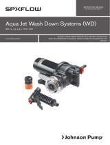
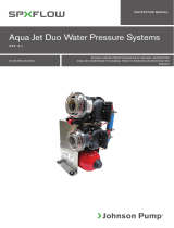
• För att undvika luftblåsor vid horisontellt
montage bör utloppet vara vänt uppåt
eller så att det befinner sig på övre
sidan av pumphuset (se Figur 2).
Utloppsslangen efter pumpen måste
vara horisontell, eller vara riktad uppåt
för att evakuera luft.
• Pumpen kan vridas till lämpligt läge i
dess klamma/fot.
• Pumpen bör ej utsättas för
värmestrålning.
• Max 60 % glykol vid
vatten-glykolblandning.
• Pumpen bör ej användas för sjö-,
havsvatten eller andra starkt förorenade
vätskor, vilket förkortar livslängden på
pumpen.
• Pumpen är konstruerad för kontinuerlig
drift.
Specifikationer
Kapslingsgrad
IP6K9K; IP67 enligt ISO 20653.
Dammtäthet IP6KX testad enligt
ISO 16750-4; punkt 5.10 med damm
blandning bestående av kalksten och
flygaska.
Brandklass
Utvändiga polymera material möter kraven
enl. UL94 klass V0.
Vikt: 4,0 kg
Temperaturer
Den totala max temperaturen är en funktion
av omgivningstemperaturens och vätskans
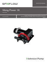
temperatur. Se diagram Figur nr 4, sid. 9.
Vätsketemperatur
-40 °C till +102 °C vid max +70 °C
omgivningstemperatur
Omgivningstemperatur vid drift
-40 °C till +105 °C vid vätsketemperatur
max +93 °C
Ovanstående värden gäller för nominell
spänning (27,2V) och 0,4 bar arbetstryck.
Lagringstemperatur,
omgivningstemperatur vid stillastående
(ej i drift)
-40 °C till +125 °C
• Motorn har en inbyggd
temperaturbegränsning som
reducerar varvtalet då temperaturen
överstiger rekommenderad nivå,
men återgår automatiskt till fullt
varvtal då temperaturen sjunkit till/
under rekommenderad nivå. Motorn
slår automatiskt ifrån då den uppnår
skadlig temperatur. Pumpen startar
åter då temperaturen har sjunkit till
återstartsnivå.
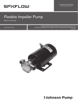
Se Figur 4. sid. 9 Temperaturbegränsningar före
automatisk varvtalsbegränsning startar.
90˚
90˚
Figur 2
4

Översättning av originalinstruktionerna IB-308
> Svenska
Systemtryck
-0,2 till 2,5 bar vid +100 °C.
Livslängd
Motorn är konstruerad för en livslängd
40.000 h vid nominell spänning
och med en omgivningstemperatur på
+40 °C.
Elektrisk installation
Nominell spänning 27,2V DC, mätt vid
motorns kabelanslutning.
Spänningsintervall: 16 – 32 V
Motorn klarar förhöjd spänning eller
förhöjd omgivningstemperatur inom
ovan angivna gränser men båda
påverkar livslängden negativt.
Startström
• Vid anslutning av huvudmatningen,
röd kabel + och svart kabel -,
laddas kondensatorerna.
Ca. 300A under 1,3 ms.
• Motorn har en strömbegränsning
om 17,5A.
Säkring
Rekommenderad storlek 25-30 Amp.
Kabelanslutningar
• Röd kabel ansluts till plus (+) pol
(kabelarea 4 mm).
• Svart kabel ansluts till
minus (-) pol (kabelarea 4 mm) .
• Vit kabel, varvtalsreglering,
Vin 0-10V eller PWM
(se ytterligare info under
varvtalsreglering) (kabelarea 1 mm).
• Blå kabel, varvtalssignal, utsignal
12 ppr (pulser per varv), 0 – 5V,
används för att registrera pumpens
varvtal (kabelarea 1mm).
Motor och elektronik har ett inbyggt skydd
mot anslutning till felaktig polaritet.
För att starta pumpen matas nominell
spänning på röd (+) och svart (-) kabel samt
på vit kabel >2V – 32V.
Spänningsområde för huvudmatning,
(röd + och svart – kabel) 16 – 32V DC.
Obs! Före installation med elektriskt
styrsystem, kontrollera att utrustningen
som skall användas har tillräcklig kapacitet
för motorns strömförbrukning som är
max. 17,5A.
Obs! Spänning >35V kan förorsaka skador
på elektroniken.
Obs! Användandet av relä för Start/stopp
funktion rekommenderas ej.
Obs! För att vid montage uppnå brandklass
UL94 Class V0 får de enskilda ledarna ej
vara öppet exponerade.
5

Översättning av originalinstruktionerna IB-308
> Svenska
Tre anslutningsalternativ
1. Trekabelanslutning
• Anslut röd och vit kabel till plus pol (+).
• Anslut svart kabel till minus pol (-).
• Varvtalssignal är tillgänglig i blå kabel
12 ppr (pulser per varv), 0 – 5V.
• Pumpen kommer ständigt att gå med fullt
varvtal.
• Varvtalsstyrning endast möjlig genom
variation av inspänningen, 16 – 32V.
2. Fyrakabelanslutning/Sleep mode/
Varvtalsreglering
• Se Bild 3, sid 6.
• Vid detta anslutningsalternativ har man
ständigt full spänning på röd (+) och svart
(-) kablarna.
• Pumpen startas då styrspänningen Vin
mellan svart kabel (-) och vit kontrollkabel
är >2V. Vid spänningen <2V stoppar
motorn och går till sleep mode.
Strömförbrukningen vid sleep mode
är 6,5 mA.
• Motorns varvtal kan varieras via Vin med
spänningar >2V och upp till 10V på den
vita kontrollkabeln.
• Vid Vin >10V på vit kontrollkabel kommer
motorn att gå med fullt varvtal.
• Max tillåten spänning för Vin = 32V,
på vit kontrollkabel.
• Varvtalssignal är tillgänglig i blå kabel
12 ppr (pulser per varv), 0 – 5V.
3. Anslutning via extern styrenhet/
processor
• Se Bild 4, sid 6.
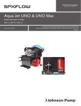
Bild 3. Fyrakabelanslutning/Sleep mode/ Varvtalsreglering
Bild 4. Anslutning via extern styrenhet/processor
6

Översättning av originalinstruktionerna IB-308
> Svenska
Varvtalsreglering
• För att starta pumpen matas nominell
spänning på röd (+) och svart (-)
kabel samt >2 V – 32V på vit kabel.
Analog varvtalsreglering
• Vin, Vit styrkabel. Vin 0-10V DC.
• 0 till <2V: Ingen funktion, sleep mode.
• ≥2 till 9,5V: Pumpen arbetar med
konstant varvtal, 2500 – 5750 rpm.
Exempel:
6 Vin; 400*4 (6-2)+2500=4100 rpm
• 10 till 32V, pumpen arbetar med
fullt varvtal.
• Styreffekt via Vin ca 400 rpm/V.
(se Figur 7, Speed Map, sid. 19)
Varvtalsreglering med PWM
(Puls Width Modulation)
• Vit styrkabel.
• PWM amplitud x PWM pulslängd =
aktuellt varvtal.
Exempel:
• PWM frekvens 100Hz -20 kHz.
Mjukvarans funktioner
Temperaturbegränsning
Den maximala temperaturen är en funktion
av omgivningstemperaturens och vätskans
temperatur. Se diagram, Fig. nr 4. sid 9.
Övre temperaturgräns utgörs av
omgivningstemperatur +80°C,
vätsketemperatur +100°C vid nominell
spänning 27,2V och arbetstrycket 0,4 bar
utan att varvtalsreduktionen startar. Lägre
vätsketemperatur innebär högre tillåten
omgivningstemperatur och omvänt.
Motorn har en inbyggd
temperaturbegränsning, som registrerar
temperaturen hos elektroniken, och
som reducerar varvtalet (derating) då
temperaturen överstiger fastställd nivå,
men återgår automatiskt till fullt varvtal då
temperaturen sjunkit under den fastställda
nivån.
Motorn slår automatiskt ifrån då den uppnår
skadlig temperatur. Pumpen startar åter
då temperaturen har sjunkit till acceptabel
temperaturnivå.
Temperaturen på motorytan är normalt ca
4 °C högre än vätsketemperaturen.
Lågspänningsskydd
Motorn stängs av då spänningen är lägre
än 13V, och återstartar automatiskt då
spänningen stiger till 15V.
Polaritetsskydd
Motor och elektronik har ett inbyggt skydd
mot anslutning till felaktig polaritet.
OBS! Om motorn har anslutits till felaktig
polaritet som sedan brutits, får den ej
återanslutas till korrekt polaritet inom
80 sekunder, ej heller får kortslutning
mellan röd och svart kabel ske inom denna
tidsperiod. Detta kan medföra skador på
motorn.
Torrkörningsskydd
Då pumpen körs utan vätska stängs den av
efter 25 min.
Detta sker genom att elektroniken mäter
pumpens momentbehov var minut.
Har pumpens momentbehov (utan vätska)
ej överstigit den förutbestämda nivån efter
25 minuter, stängs pumpen av.
För återstart måste all elförsörjning
(kablarna för + plus, röd, - minus, svart
och Vin, vit) göras helt spänningsfria under
5 minuter.
Spänningstransienter
Elektroniken har ett inbyggt skydd mot
spänningstransienter, i enlighet med EMC
standarder.
Notera att spänningar över 35V kan skada
elektroniken.
Strömbegränsning
Motorn har en inbyggd strömbegränsning,
17,5 Ampere, vilket ger en maximal
effektförbrukning om 475W, vid nominell
spänning.
Låst rotor
Motorn har ett inbyggt skydd för att
förhindra överhettning då rotorn är låst.
14V*50%=7V, 400*5 (7-2)+2500=4500 rpm
7

Översättning av originalinstruktionerna IB-308
> Svenska
Genomförda verifikationstester
• Pump/motorenhet vibrationstestad enl.
ISO 16750-3; punkt 4.1.2.7 Test VII
”Commercial vehicle, sprung masses”.
• Pump/motorenhet testad för mekanisk
chock enl. ISO 16750-3; punkt 4.2.2
“Test for devices on rigid points on
body and on frame”.
• Pump/motorenhet med fot möter
vibrations kraven enl.
ISO 16750-3; punkt 4.1.2.7 Test VII
”Commercial vehicle, sprung masses”.
• Salt spray test enl.
IEC 60068-2-52, Serverity 5 enl.
ISO 16750-4, Annex A Kod E;
“Mounting under body/weel housing,
sprung masses”. 28 dygn.
• EMC (se Radioavstörning sid. 3)
• Kapslingsgrad IP6K9K testad enligt
standard ISO 16750-4; Item 5.10.2
med referenser till ISO 20653 och
IEC 60068-2-68.
• Dammtest, IP6KX, utförd med 50 %
kalkstenspulver och 50 % flygaska.
• Gnistskydd enl. ISO 8846.
Klimattester
• Låg temperatur test enl.
ISO 16750-4; Item 5.1.1.
Omgivningstemperatur
-40 °C / 24 tim.
• Hög temperatur test enl.
ISO 16750-4; Item 5.1.2.
Omgivningstemperatur
+80 °C, vätsketemperatur
+100 °C / 96 tim.
• Temperatur steg test, enl
ISO 16750-4; Item 5.2.
Omgivningstemperaturen justerad i
steg om 5 °C, från +20 °C ned till
-40 °C och sedan upp till +80 °C.
• Cyklisk temperatur test, enl.
ISO 16750-4; Item 5.3.
Omgivningstemperaturen cyklad från
+20 °C, ned till -40 °C (pumpen
startas), upp till 80 °C (pumpen
stoppas) och åter till +20 °C.
Cykeln upprepas 30 ggr.
• Ice water shock test, enl.
ISO 16750-4; item 5.4.3.
”Submersion test”. Tmax=80 °C,
Is vatten temp 0 - +4 °C.
Dränktid 5 min.
• ”Damp heat, steady test” enl. ISO
16750-4; item 5.7 and IEC 60068-2-
78.
• “Composite temperature/humidity
cyclic test” enl.
ISO 16750-4; Item 5.6.2.3 och
IEC 60068-2-38 test Z/AD
• “Dewing test” enl. ISO 16750-4;
Item 5.6.2.4 och
IEC 60068-2-30, test Db.
Avfallshantering/Materialåtervinning
Vid avfallshantering skall produkten lämnas för
destruktion/återvinning enligt gällande lagstiftning.
Vid tillämpliga fall demonteras och sorteras
produkten i ingående materialfraktioner.
8

Översättning av originalinstruktionerna IB-308
> Svenska
Figur 4. Temperaturbegränsningar före automatisk varvtalsbegränsning startar
9

Original instructions IB-308
> English
Typical applications
Circulation in heating- and cooling system
for buses, trains and boats, etc. All-around
pump wherever self- priming is not essential.
Features
• Centrifugal pump (must be primed)
• Magnetic drive (no shaft seal/
mechanical seal)
• Brushless motor
• Long service life
• Designed for continuous duty
• Wide temperature range
• Built-in thermal overload protection
• Derating, automatic speed control at
overheating
• Speed control
• Tacho out signal
• Locked rotor protection
• Reversed polarity protection
• Current limitation
• Low voltage protection
• Dry run protection
EMC approved according to:
UN ECE R10 rev. 5, with references to
CISPR 12, CISPR 25, ISO 11452-2, -3,
-4, -5 and ISO 7637.
EN61000-6-3:2007 + A1:2011, +AC:2012
Class B.
EN 61000-6-2:2005 + AC: 2005 Industrial
EN 60945:2002 Marine, Chapter 9 and 10.
EN 55014-1:2006 + A1:2009 + A2: 2011
EN55014-2:1997 + A1:2001 + A2: 2008
+ AC: 1997
Technical description
Parts in contact with liquid
Pump housing: Aluminum, black
anodized
Impeller: PA12 GF
Intermediate part: PPA GF
Bushing: Resin bonded carbon
Shaft: Stainless steel,
hardened
Impeller magnet: PA12 bonded ferrite
Magnet housing: Stainless steel
O-rings: EPDM, peroxide cured
Screw: Stainless steel
Driving unit incl motor
Drive magnet: Ferrite segments
Screws Steel, surface treatment
Zn/Ni with sealer and wax
Motor: Permanent magnet
brushless motor with ball
bearings and electronics
included
Motor housing: Aluminum, black
anodized
Bracket: Stainless steel
Degree of protection:
IP6K9K; IP67 (ISO 20653)
Connections:
38 mm (1½") hose
Type specification
Pressure and capacity data:
See Figure 1 and Figure X, page 16
Spare parts:
See Figure 5, page 18
Service kits:
Hydraulic kit: 09-47650
Pumphousing kit: 09-47655
Bracket kit 09-47661
Warnings
• The pump should be connected to
a SELV (Safety Extra Low Voltage)
system.
• Voltage >35V may cause damage to
the electronics.
• Maximum allowed voltage between
housing and motor ground (black wire -)
is 50V. Capacitance between housing
and motor ground is 440 nF.
• Pump and motor surfaces may be hot.
Do not touch. Risk for injuries.
• Do not use the pump with lake water,
seawater, flammable or corrosive
liquids.
• Soiled liquids reduce service life of the
pump.
Circulation Pump CM100HF
Part. No Designation Voltage Connection
10-13578-02 CM100HF Al-1Bl 27,2V D38 27,2V 38 mm/1½"
10

Original instructions IB-308
> English
Installation recommendations
• The CM-series pumps are normal-
priming centrifugal pumps and should
be mounted in a manner that ensures
that they are always flooded or else
they should be primed before being
switched on. In a closed system the
pump should be placed at a low point.
• The pump should not be run dry, even
if it withstands a shorter time of dry
running. Max dry running 25 minutes. If
the pump is run dry, noise may occur.
• Avoid dry running because it will always
cause increased wear.
• Use full hose diameter at the pump
inlet. Reduced hose diameter at inlet
gives reduced performance and a risk of
cavitation, which can damage the pump.
• The direction of rotation is clock-wise,
viewed from the body (see direction of
flow arrow, Fig. 3, page 17).
• The pump can be installed horizontally
or vertically, on a flat surface.
• To avoid airlocks when mounted
horizontally, the body should be turned
in such a way that the outlet is directed
upwards or is placed on the upper
side of the pump body (see sketch).
The outlet hose after the pump must
be horizontal or directed upwards to
evacuate air.
• The pump can be turned within the
bracket to a suitable position.
• The pump should not be exposed to
thermal radiation.
• Max 60% glycol/water mixture should
be used.
• The pump should not be used with lake
water, sea water or other soiled liquids,
which reduce service life of the pump.
• The pump is designed for continuous
duty.
Specifications
Enclosure
IP6K9K; IP67 according to ISO 20653.
Ingression of dust IP6KX tested according
ISO 16750-4; Item 5.10 with dust mixture
consisting of limestone and fly ash.
Flammability
External polymer materials meet
requirements according to UL94 Class V0.
Weight: 4.0 kg (8.8 lb)
Temperatures
The total temperature limits are a function of
ambient temperature vs liquid temperature.
See graph Figure 4, page 15.
Liquid temperature
-40°C to +102°C at max ambient
temperature +70°C
(-40°F to + 216°F at max ambient
temperature +158°F)
Ambient temperature in operation
-40°C to +105°C at liquid temperature
max +93°C
(-40°F to +221°F at liquid temp +199°F).
Above values valid at 27.2V rated voltage and
0,4 bar (5,8 PSI) operating pressure.
Storage ambient temperature
(not in operation)
-40°C to +125°C (-40°F to +257°F).
• The motor has a built in temperature
limitation. The speed will be reduced
when the temperature reaches the top
limit. The speed will return to full speed
when temperature has cooled down to
recommended limit.
• The motor will automatically shut off when
it reaches the damaging limit. The motor
will start again when it has cooled down
to an acceptable level.
System pressure
-0,2 to 2,5 bar at +100°C (+212°F).
Service Life
The motors are designed for a service life
of 40.000 hours at nominal voltage and
ambient temperature of +40°C (+104°F).
90˚
90˚
Figure 2
11

Original instructions IB-308
> English
Electric Installation
Nominal voltage 27,2V DC, measured at the
cable connections of the motor.
Voltage range: 16 – 32V DC
The motor can withstand excessive voltage
or excessive ambient temperature as long as
they are within the given ranges. However,
both excessive voltage and ambient
temperature will have a negative impact on
the service life of the pump.
In rush current
• When connecting the main power
supply, red lead to positive (+) terminal
and black lead to negative (-) terminal
the capacitors will become charged.
Approx. 300A during 1,3 ms.
• Current is limited electronically to 17,5A.
Fuse: Recommended fuse size 25 – 30A.
Cable connections
• Red to positive terminal (+),
wire size AWG 12.
• Black to negative terminal (-),
wire size AWG 12.
• White, control cable, Vin 0-10V or PWM
(see item Speed control below),
wire size AWG 16.
• Blue, speed signal, Tacho out,
12 ppr (pulses per revolution) 0 – 5V
used to register pump speed,
wire size AWG 16.
The motor has a built in polarity protection to
avoid damage if wrongly connected.
In order to start pump, supply nominal voltage
at main power supply, red cable + and black
cable - and >2V – 32V at white control cable.
Voltage range for main power supply
(red + and black – cable) 16 – 32V DC.
Use of a relay for start/stop function is not
recommended.
Note! Before installation with electrical control
systems, check that equipment to be used is
of sufficiently rated capacity to accept ampere
draw of motor, 17,5 Amp.
Note! Voltage >35V may cause damage to the
electronics.
Note! In order to obtain flammability according
to UL94 Class V0, the separate wires must not
be exposed.
Three Connection Alternatives
1. Three wire connection
• Connect red and white wire to plus
terminal (+).
• Connect black wire to negative
terminal (-).
• Tacho out signal is available at
blue wire, 12 ppr (pulses per revolution),
0 – 5V.
• The pump will operate at full speed.
• Speed control only available by variation
of supply voltage, 16- 32V.
2. Four wire connection/sleep mode/
speed control
• See image 3, page 13.
• Using this alternative, full voltage is
required at main power supply (red (+)
terminal and black (-) negative terminal).
• The pump starts up at voltage at white,
control wire, >2V. At voltage <2V pump
stops and goes into sleep mode. Power
consumption at sleep mode is 6,5 mA.
• Pump speed can be controlled by
Vin >2V and <10V at the white control wire.
At voltage >10V at the control wire pump
runs at full speed.
PWM signal into white cable is also useful
in order to control speed.
• Tacho out signal is available at blue wire,
12 ppr (pulses per revolution), 0 – 5V.
• Max Voltage for Vin = 32V on white control
wire.
3. Connection/control via an external
Micro controller
• See Image 4, page 13.
Speed control
• In order to start up the pump, supply
nominal voltage at main power supply, red
(+) and black (-) and >2V – 32V at white
wire.
Analogue speed control
• White control wire.
• Vin 0 – 10V DC.
• 0 - <2V, no operation, sleep mode.
• >2V – 9,5V, pump operates with Constant
speed, 2500 – 5750 rpm.
Example:
6 Vin; 400*4 (6-2) + 2500 =4100 rpm
(see Figure 7, Speed Map, Page 19)
• 10 to 32V, pump operates at full speed
• Speed control by Vin, approx.
400 rpm/V.
12

Original instructions IB-308
> English
Speed control via PWM
(Puls Width Modulation)
• White control wire
• PWM amplitude x PWM duty cycle =
speed
Example:
Software functions
Temperature limitations
The maximum temperatures are a function of
ambient temperature vs liquid temperature. (See
graph, Figure. 4, page 15).
Nominal upper temperature limit is ambient temp.
+80°C, and liquid temp. +100°C at nominal
voltage 27,2V and operating pressure 0,4 bar,
Image 4. Connection/control via an external Micro controller
Image 3. Four wire connection/sleep mode/speed control
without any derating. Lower liquid temperature
means higher ambient temperature and vice
versa.
The motor has a built-in temperature limitation
function, which senses the temperature at
the circuit board and reduces the speed at
temperatures above the set level. The speed
returns to full speed when the temperature
has decreased below the set level.
The motor will shut off when temperature
reaches a critical level, but will restart
automatically at the acceptable level.
The temperature at motor surface is approx.
4°C higher than the liquid temperature.
14V*50%=7V, 400*5 (7-2)+2500=4500 rpm
13

Original instructions IB-308
> English
Low voltage protection
Motor shuts off at main power supply <13V, and
restarts automatically when voltage reaches 15V.
Reverse polarity protection
Motor and electronics include a reverse polarity
protection in order to protect from faulty polarity
connections.
Note! If the wires have been connected
incorrectly, a minimum of 80 seconds must pass
before reconnecting. Short circuiting the red and
black wires within 80 seconds will also cause
damage to the motor.
Dry run protection
When the pump runs with no liquid, it will shut off
after 25 minutes.
The electronics sense torque requirement of the
pump every minute. If the torque requirement
has not exceeded the stipulated level after 25
minutes, the pump will shut off.
In order to restart, all power supply must be
disconnected for 5 minutes (red + cable, black –
cable and white control cable).
Voltage transients
The pump includes a protection for voltage
transients in accordance with EMC standard
Note! Voltage over 35 volt may damage the
electronics.
Current limitation
The motor has an internal current limitation, 17,5
Ampere, which gives a max power consumption
of 410W at nominal voltage.
Locked rotor protection
The motor has a built in protection if the rotor
is locked, which protects the motor from
overheating.
Verification tests
• Vibration test of pump/motor unit according
to ISO 16750-3; Item 4.1.2.7 Test VII
Commercial vehicle, sprung masses.
• Mechanical shock test of pump/motor unit
according to ISO 16750-3; Item 4.2.2 Test
for devices on rigid points on body and on
frame.
• Pump/motor unit including bracket meets
vibrations requirements according to ISO
16750-3; Item 4.1.2.7 Test VII ”Commercial
vehicle, sprung masses”.
• Salt spray test according to
IEC 60068-2-52, Severity 5 enl.
ISO 16750-4, Annex A Cod E; Mounting
under body/wheel housing, sprung masses.
28 days.
• EMC, see tests, page 10.
• Enclosure IP6K9K tested according to
standard ISO 16750-4; Item 5.10.2 with
reference to ISO 20653 and
IEC 60068-2-68. Dust test IP6KX tested
with 50% limestone and 50% fly ash.
• Protection against ignition of surrounding
flammable gases, according to ISO 8846.
Environment tests
• Low temperature test, according to ISO
16750-4; Item 5.1.1. Ambient temperature
-40°C / 24 hours
• High temperature test, according to ISO
16750-4; Item 5.1.2. Ambient temperature
+80°C, liquid temperature +100° / 96
hours
• Temperature step test, according to
ISO 16750-4; Item 5.2. Ambient
temperature in steps of 5°C, from +20°C
down to -40°C and up to +80°C.
• Cyclic temperature test, in reference to ISO
16750-4; Item 5.3. Ambient temperature
cycled from +20°C,
down to -40°C (pump start),
up to +80°C (pump stopped)
and cool down to +20°C. This cycle
repeated 30 times.
• Ice water shock test, in reference to
ISO 16750-4; item 5.4.3. Submersion test.
Tmax=80°C, Ice water temp
0 - +4°C. immersion time 5 min.
• Damp heat, steady test” according to
ISO 16750-4; item 5.7 and
IEC 60068-2-78.
• “Composite temperature/humidity cyclic
test” according to ISO 16750-4; Item
5.6.2.3 and IEC 60068-2-38 test Z/AD
• “Dewing test” according to
ISO 16750-4; Item 5.6.2.4 and
IEC 60068-2-30, test Db.
Waste management/Recycling
Dispose of the product in accordance with
existing regulations. Where appropriate,
dismantle and sort the product by its materials.
14

Original instructions IB-308
> English
Figure 4. Temperature limits before start of derating
15

Pressure and capacity data
Figure 1.
Performance for pump type
CM100HF AL-1BL 27,2V D38
Tryck och flöde
Figur 1.
Prestanda för pumptyp
CM100HF AL-1BL 27,2V D38
0102030405060708090 100 110 120 130 140 150 160 170 180 190 200
0,0
0,2
0,4
0,6
0,8
1,0
1,2
1,4
1,6
1,8
Flow resistance
Flow
Current
P.tot (bar)
Flow (l/min)
p.tot (bar) CM100 HF38
P.tot (bar) Vin 27,2V
Speed
0
1
2
3
4
5
6
7
8
9
10
11
12
13
14
15
16
17
18
19
20
Amperage (A) Vin 27,2V
Amperage (A)
2400
2600
2800
3000
3200
3400
3600
3800
4000
4200
4400
4600
4800
5000
5200
5400
5600
5800
6000
6200
6400
n (r/min) Vin 27,2V
n (r/min)
0102030405060708090 100 110 120 130 140 150 160 170
0,0
0,1
0,2
0,3
0,4
0,5
0,6
0,7
0,8
0,9
1,0
1,1
1,2
1,3
p.tot (bar)
Flow (l/min)
(Vin 3,0V) p.tot (bar)
(Vin 4,0V) p.tot (bar)
(Vin 5,0V) p.tot (bar)
(Vin 6,0V) p.tot (bar)
(Vin 7,0V) p.tot (bar)
(Vin 8,0V) p.tot (bar)
(Vin 9,0V) p.tot (bar)
(Vin 10,0V) p.tot (bar)
2
3
4
5
6
7
8
9
10
11
12
13
14
15
(Vin 3,0V) Amperage (A)
(Vin 4,0V) Amperage (A)
(Vin 5,0V) Amperage (A)
(Vin 6,0V) Amperage (A)
(Vin 7,0V) Amperage (A)
(Vin 8,0V) Amperage (A)
(Vin 9,0V) Amperage (A)
(Vin 10,0V) Amperage (A)
Amperage (A)
1800
2100
2400
2700
3000
3300
3600
3900
4200
4500
4800
5100
5400
5700
(Vin 3,0V) n (r/min)
(Vin 4,0V) n (r/min)
(Vin 5,0V) n (r/min)
(Vin 6,0V) n (r/min)
(Vin 7,0V) n (r/min)
(Vin 8,0V) n (r/min)
(Vin 9,0V) n (r/min)
(Vin 10,0V) n (r/min)
n (r/min)
EN SE
EN SE
Figure 6 Figur 6
16

Dimensions
Figure 3.
Dimensions Pump type
CM100HF AL-1BL D38
Dimensioner
Figur 3.
Dimensioner pumptyp
CM100HF AL-1BL D38
+Red
-Black
ControlWhite
Blue tachoout
Cablelenght 500u10
Ø38
Ø39,9
Ø38
Ø39,9
87
Ø126
179
191
37,5
22
110
115
Ø9(4x)Ø7(4x)
40
60
85
45
35,3
23
60,7
+Red
-Black
ControlWhite
Blue tachoout
Cablelenght 500u10
Ø38
Ø39,9
Ø38
Ø39,9
87
Ø126
179
191
37,5
22
110
115
Ø9(4x)Ø7(4x)
40
60
85
45
35,3
23
60,7
EN SE
17

Figure 5.
Split view
x/ included in spare part kit 09-47650
y/ included in spare part kit 09-47655
Figur 5.
Sprängskiss
x/ Ingår i reservdelssats 09-47650
y/ Ingår i reservdelssats 09-47655
EN SE
1
2
3x
4x
5x
6x
7y
8x,y
9x
13z
10y
EN: Components
Pos Nos Description Comment
1 1 Motor 27,2V Incl. drive magnet
2 1 Magnet housing
3 1 Impeller magnet
4 1 Intermediate part
5 1 Impeller
6 1 Screw M4x10 Left threaded
7 1 Pump housing Ø 38 mm/1½" CM100HF dia 38
8 1 O-ring 91,67x3,53 EPDM
9 1 O-ring 91x2,5 EPDM
10 7 Screw, thread forming M5x25
13 1 Bracket complete
SE: Ingående delar
Pos Ant Benämning Anm.
1 1 Motor 27,2V Inkl. drivmagnet
2 1 Magnethus
3 1 I mpeller magnet
4 1 Mellanfläns
5 1 Pumphjul
6 1 Skruv M4x10 Vänstergängad
7 1 Pumphus Ø 38 mm/1½" CM100HF Ø 38
8 1 O-ring 91,67x3,53 EPDM
9 1 O-ring 91x2,5 EPDM
10 7 Skruv, självgängande M5x25
13 1 Fäste komplett
18

Figure 7
Speed Map
Figur 7
Speed Map
EN SE
1
2
3x
4x
5x
6x
7y
8x,y
9x
13z
10y
012345678910 24 28 32
0
1000
2000
3000
4000
5000
6000
n (r/min)
Vin control voltage (V)
n (r/min)
Full speed
EN: Components
Pos Nos Description Comment
1 1 Motor 27,2V Incl. drive magnet
2 1 Magnet housing
3 1 Impeller magnet
4 1 Intermediate part
5 1 Impeller
6 1 Screw M4x10 Left threaded
7 1 Pump housing Ø 38 mm/1½" CM100HF dia 38
8 1 O-ring 91,67x3,53 EPDM
9 1 O-ring 91x2,5 EPDM
10 7 Screw, thread forming M5x25
13 1 Bracket complete
SE: Ingående delar
Pos Ant Benämning Anm.
1 1 Motor 27,2V Inkl. drivmagnet
2 1 Magnethus
3 1 I mpeller magnet
4 1 Mellanfläns
5 1 Pumphjul
6 1 Skruv M4x10 Vänstergängad
7 1 Pumphus Ø 38 mm/1½" CM100HF Ø 38
8 1 O-ring 91,67x3,53 EPDM
9 1 O-ring 91x2,5 EPDM
10 7 Skruv, självgängande M5x25
13 1 Fäste komplett 19

CM100HF
HIGH QUALITY BRUSHLESS
MOTOR CIRCULATION PUMPS
FOR MARINE & AUTOMOTIVE
APPLICATIONS
IB-308/R03 ISSUED 10/2018
COPYRIGHT © 2018 SPX FLOW INC.
SPX FLOW, Inc. reserves the right to incorporate our latest design and material changes without notice or obligation.
Design features, materials of construction and dimensional data, as described in this bulletin, are provided for your information only and
should not be relied upon unless confirmed in writing. Please contact your local sales representative for product availability in your region.
For more information visit www.spxflow.com.
The green “
”
and “
” are trademarks of SPX FLOW, Inc.
Customer Service & Support - Johnson Pump Marine
SE +46 19 21 83 10
johnson-pump.marine@spxflow.com
US +1 847 671-7867
jp-customerservice@spxflow.com
AUS +61 03 9589 9222
ft.aus.cs@spxflow.com
For more information about our worldwide locations, approvals, certifications, and local representatives,
please visit Johnson Pump - Marine at www.spxflow.com/johnson-pump-marine
1/20