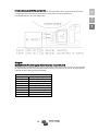
Victron energy 12-250 Användarmanual
- Kategori
- Nätadaptrar
- Typ
- Användarmanual

Manual
EN
Håndbok
NO
Handbok
SV
Phoenix Inverter VE.Direct
12 | 250 12 | 375 12 | 500 12 | 800 12 | 1200
24 | 250 24 | 375 24 | 500 24 | 800 24 | 1200
48 | 250 48 | 375 48 | 500 48 | 800 48 | 1200

1
EN NO SV
1. IMPORTANT SAFETY INSTRUCTIONS – SAVE THESE
INSTRUCTIONS!
In general
Please read the documentation supplied with this product first, so that you are familiar with the safety
signs en directions before using the product.
This product is designed and tested in accordance with international standards. The equipment should
be used for the designated application only.
Warning – These servicing instructions are for use by qualified
personnel only. To reduce the risk of electric shock, do not perform
any servicing other than that specified in the operating instructions
unless you are qualified to do so.
WARNING: ELECTRIC SHOCK HAZARD
The product is used in conjunction with a permanent energy source (battery). Input and/or output
terminals may still be dangerously energized, even when the equipment is switched off. Always
disconnect the battery before carrying out maintenance or servicing the product.
The product has no internal user-serviceable components. Do not remove the front plate or operate the
product if any panels have been removed. All servicing must be undertaken by qualified personnel.
Please read the installation instructions in the installation manual before installing the equipment.
This is a Safety Class I product (supplied with a protective grounding terminal). The chassis must be
grounded. A grounding point is located on the outside of the product. Whenever it is likely that the
grounding protection has been damaged, the product must be turned off and secured against
unintended operation; please contact qualified service staff.
The AC output is isolated from the DC input and the chassis unless the unit is equipped with a Ground
Fault Circuit Interrupter (GFCI). Units with a GFCI have AC output neutral connected to chassis
inside the device by default. A qualified installer should check this connection since it is necessary
for the GFCI to function properly. Local regulations may require a true neutral. In this case one of the
AC output wires must be connected to the chassis, and the chassis must be connected to a reliable
ground. Please note that a true neutral is needed to ensure correct operation of an earth leakage circuit
breaker.
Ensure that the equipment is used under the correct ambient conditions.
Never operate the product in a wet or dusty environment.
Never use the product where there is a risk of gas or dust explosions.
Ensure there is adequate free space (10 cm) for ventilation around the product and check that the
ventilation vents are not blocked.
This appliance is not intended for use by persons (including children) with reduced physical,
sensory or mental capabilities, or lack of experience and knowledge, unless they have been
given supervision or instruction concerning use of the appliance by a person responsible for
their safety.
Children should be supervised to ensure that they do not play with the appliance.
Use of an attachment not recommended or sold by the marine unit manufacturer may result in a risk of
fire, electric shock, or injury to persons.

2
2. Description
VE.Direct communication port
The VE.Direct port can be connected to:
• A computer (VE.Direct to USB interface cable needed)
• Apple and Android smartphones, tablets and other devices (VE.Direct to Bluetooth Smart dongle
needed)
Fully configurable
• Low battery voltage alarm trip and reset levels
• Low battery voltage cut-off and restart levels, or Dynamic Cut-off
• Output voltage 210 - 245 V
• Frequency 50 Hz or 60 Hz
• ECO mode on/off and ECO mode sense level
Monitoring
Battery voltage, AC Output voltage, load indicator, alarms
Proven reliability
The full bridge with toroidal transformer topology has proven its reliability over many years.
The inverters are short circuit proof and protected against overheating, whether due to overload or high
ambient temperature.
High start-up power
Needed to start loads such as power converters for LED lamps, filament lamps or electric tools.
ECO mode
When in ECO mode, the inverter will switch to standby when the load decreases below a preset value. It
will switch on and check every few seconds, adjustable, if the load has increased again.
Remote on/off connector
A remote on/off switch can be connected to a two pole connector or between battery plus and the left
hand contact of the two pole connector.
LED diagnosis
A red and a green LED indicate inverter operation and status of the different protections.
To transfer the load to another AC source: the automatic transfer switch
For our low power inverters we recommend our Filax Automatic Transfer Switch. The Filax features a
very short switchover time (less than 20 milliseconds) so that computers and other electronic equipment
will continue to operate without disruption.
Available with different output sockets
Schuko, UK (BS-1363), AU/NZ (3112) or IEC-320 (male plug included)

3
EN NO SV
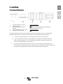
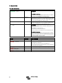
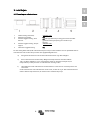
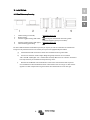
3. Installation
3.1 Location of the inverter
1
Ceiling mounting (inverted).
Not recommended
2.
Base mounting.
OK
3
Vertical wall mounting, fan at
bottom.
OK (beware of small objects falling through the
ventilation openings on top).
4
Vertical wall mounting, fan on top.
Not recommended
5
Horizontal wall mounting.
OK
For best operating results, the inverter should be placed on a flat surface. To ensure a trouble-free
operation of the inverter, it must be used in locations that meet the following requirements:
a) Avoid any contact with water. Do not expose the inverter to rain or moisture.
b) Do not place the unit in direct sunlight. Ambient air temperature should be between
-20 °C and 40 °C (humidity < 95% non-condensing). Note that in extreme situations the
inverter’s case temperature can exceed 70 °C.
c) Do not obstruct the airflow around the inverter. Leave at least 10 centimetres clearance
around the inverter. When the inverter is running too hot, it will shut down. When the inverter
has reached a safe temperature level the unit will automatically restart again.

4
3.2 Connection to the battery
In order to utilize the full capacity of the product, batteries with sufficient capacity and battery cables
with sufficient cross section should be used. See table:
12/250
24/250
48/250
12/375
24/375
48/375
Minimum battery cap.
30 Ah
20 Ah
10 Ah
40 Ah
30 Ah
15 Ah
Internal DC fuse 2 x 30 A 30 A 25 A 2 x 40 A 40 A 25 A
Fuse type (Mfr.:
Littelfuse)
ATOF
32 V
ATOF
32 V
FKS
80 V
ATOF
32 V
ATOF
32 V
FKS
80 V
Fuse replaceble no no no no no no
Recommended DC cable cross-section (mm2)
0 – 1.5 m
4 mm²
2.5 mm²
1.5 mm²
6 mm²
4 mm²
2.5 mm²
1.5 – 3 m
6 mm²
4 mm²
2.5 mm²
10 mm²
6 mm²
4 mm²
12/500
24/500
48/500
12/800
24/800
48/800
Minimum battery cap.
60 Ah
40 Ah
20 Ah
100 Ah
50 Ah
30 Ah
Internal DC fuse
3 x 35 A
2 x 25 A
30 A
125 A
2 x 40 A
2 x 20 A
Fuse type (Mfr.:
Littelfuse)
ATOF
32 V
ATOF
32 V
FKS
80 V
MIDI
32 V
ATOF
32 V
FKS
80 V
Fuse replaceble
no
no
no
yes
no
no
Recommended DC cable cross-section (mm2)
0 – 1.5 m
6 mm²
6 mm²
4 mm²
16 mm²
6 mm²
4 mm²
1.5 -3 m
10 mm²
10 mm²
6 mm²
25 mm²
10 mm²
6 mm²
12/1200
24/1200
48/1200
Minimum battery cap.
150 Ah
60 Ah
30 Ah
Internal DC fuse
200 A
100 A
50 A
Fuse type (Mfr.:
Littelfuse)
MIDI
32 V
MIDI
32 V
MIDI 58V
Fuse replaceble
yes
yes
yes
0 – 1.5 m
25 mm²
10 mm²
6 mm²
1.5 -3 m
35 mm²
16 mm²
10 mm²
The inverters are fitted with an internal DC fuse (see table above for rating). If the DC cable length is
increased to more than 1,5m, an additional fuse or DC circuit breaker must be inserted close to the
battery. Important note: for UL certified (NEMA GFCI) inverters it is mandatory to install a fuse or DC
circuit breaker close to the battery, even if the cable length is less than 1,5m.
Reverse polarity connection of the battery wires will blow the internal fuse and can damage the inverter.
The internal fuse is not always replaceble (see table above).
3.3 Wire size for connecting the inverter chassis to ground
The earth conductor from the earth lug on the chassis to ground should have at least half the cross-
section of the conductors used for the battery connection: see Appendix B.
3.4 Connection to the load
Never connect the output of the inverter to another AC source, such as a household AC wall outlet or a
generator.
The inverter does not have a fuse in the AC output. The AC cabling is protected by a fast-acting current
limiter in case of a short circuit and an overload detection mechanism which mimics the characteristics
of a fuse (i.e. faster shutdown with larger overload). It is important to size your wiring properly based on
the inverters’ power rating.
3.5 Connecting the inverter neutral output to the chassis/ground

5
EN NO SV
The AC output is isolated from the DC input and the chassis. Local regulations may require a true neutral.
In this case one of the AC output wires must be connected to the chassis, and the chassis must be
connected to a reliable ground: see appendix A.
3.6 Remote on/off connector
A remote on/off switch can be connected to the two-pole connector. Alternatively, the left-hand contact
of the connector can be switched to battery positive: useful in automotive applications, wire it to the
ignition contact.
Note that also the front switch needs to set to either On or ECO for the inverter to start.
3.7 Configuration
The inverter is ready for use with the factory settings (see specifications), and can be configured with a
computer (VE.Direct to USB interface cable needed), Apple and Android smartphones, tablets and other
devices (VE.Direct to Bluetooth Smart dongle needed).

6
4. Operation
4.1 LED definitions
Green LED
Status
Trouble shooting
●●●●●●●●
Solid on
Inverter on
Red LED Off
status OK
Red LED On or blinking:
The Inverter is still on, but will shut down when the condition
gets worse. See red LED table for warning reason
●●------
Slow single pulse
ECO mode
If the inverter keeps switching on and off while there is a load
connected, the load may be too small compared to the actual
ECO mode settings. Increase the load or change ECO mode
settings. (minimum ECO mode setting: 15 W)
●-●-----
Fast double pulse
Off and waiting
Inverter did shut down because of a protection. The inverter
will restart automatically as soon as all alarm conditions are
cleared. See red LED state for the shutdown reason.
--------
Off
Inverter off
Red LED Off
Check the On/Off/ECO switch: it should be in On position or in
ECO position.
Check Remote on/off connector.
Check DC cable connections and fuses.
Inverter fuse blown: the inverter has to be returned for service.
Red LED On or blinking
The inverter did shut down because of a protection. It will no
longer automatically restart. The red LED indicates the reason
for shutdown. Remove the cause and then restart the inverter
by switching it Off, and then back On.
Red LED
Definition
Trouble shooting
●●●●●●●● Solid on
Overload
Reduce load
●●●●----
Slow blink
Low batt.
Recharge or replace battery
Check DC cable connections
Check cable cross section as it may be insufficient.
See section 4.3 Protections and automatic restarts for manual
and automatic restart behavior.
●-●-●-●- Fast blink
High batt.
Reduce DC input voltage, check for faulty charger
●-●-----
Double pulse
High temp.
Reduce load and/or move inverter to better ventilated area
●---●---
Fast single pulse
High DC ripple
Check DC cable connections and cable cross section.

7
EN NO SV
4.2 ECO Mode
Set the front switch to ECO mode to reduce the power consumption in no-load operation. The inverter
will automatically switch off as soon as it detects that there is no load connected. It then switches on,
briefly, every 2,5 seconds to detect a load. If the output power exceeds the set level, the inverter will
continue to operate.
The default ECO mode wake-up minimum power is 15 Watt.
The default ECO mode search interval is 2.5 seconds
Note that the required ECO mode settings are heavily dependent on the type of load: inductive,
capacitive, non-linear. Adjustment may be needed.
4.3 Protections and automatic restarts
Overload
Some loads like motors or pumps draw large inrush currents in a start-up situation. In such
circumstances, it is possible that the start-up current exceeds the over current trip level of the inverter. In
this case the output voltage will quickly decrease to limit the output current of the inverter. If the over
current trip level is continuously exceeded, the inverter will shut down: wait 30 seconds and then restart.
After three restarts followed by another overload within 30 seconds of restarting, the inverter will
shutdown and remain off. The LEDs will signal shutdown due to overload. To restart the inverter, switch
it Off, then On.
Low battery voltage (adjustable)
The inverter will shut down when the DC input voltage drops below the low battery shutdown level.
After a minimum delay of 30 seconds, the inverter will restart if the voltages rise above the low battery
restart level.
After three restarts followed by a low battery shutdown within 30 seconds of restarting, the inverter will
shutdown and stop retrying. The LEDs will signal low battery shutdown. To restart the inverter, switch it
Off, and then On, or recharge the battery: as soon as the battery has risen and then stays above the
Charge detect level for 30 seconds, it will switch on.
See the Technical Data table for default low battery shutdown and restart levels. They can be changed
with VictronConnect (computer or app).
Alternatively Dynamic Cut-off can be implemented, see
https://www.victronenergy.com/live/ve.direct:phoenix-inverters-dynamic-cutoff
High battery voltage
Reduce DC input voltage and/or check for a faulty battery- or solar-charger in the system. After shutting
down due to a high battery voltage, the inverter will first wait 30 seconds and then retry operation as
soon as the battery voltage has dropped to acceptable level. The inverter will not stay off after multiple
retries.
High temperature
A high ambient temperature or enduring high load may result in shut down to over temperature. The
inverter will restart after 30 seconds. The inverter will not stay off after multiple retries. Reduce load
and/or move inverter to better ventilated area.
High DC ripple
High DC ripple is usually caused by loose DC cable connections and/or too thin DC wiring. After the
inverter has switched off due to high DC ripple voltage, it waits 30 seconds and then restarts.
After three restarts followed by a shutdown due to high DC ripple within 30 seconds of restarting, the
inverter will shutdown and stops retrying. To restart the inverter, switch it Off and then On.
Continuous high DC ripple reduces life expectancy of the inverter.

8
5. Technical data
Phoenix Inverter
12 Volt
24 Volt
48 Volt
12/250
24/250
48/250
12/375
24/375
48/375
12/500
24/500
48/500
12/800
24/800
48/800
Cont. power at 25 °C (1)
250 VA
375 VA
500 VA
800 VA
Cont. power at 25 °C / 40 °C
200 / 175 W
300 / 260 W
400 / 350 W
650 / 560 W
Peak power
400 W
700 W
900 W
1500 W
Output AC voltage / frequency (adjustable)
230 VAC or 120 VAC +/- 3% 50Hz or 60Hz +/- 0.1%
Input voltage range
9.2 - 17 / 18.4 - 34.0 / 36.8 - 62.0 VDC
Low battery shut down (adjustable)
9.3 / 18.6 / 37.2 VDC
Low battery restart & alarm (adjustable)
10.9 / 21.8 / 43.6 VDC
Battery charged detect (adjustable)
14.0 / 28.0 / 56.0 VDC
Max. efficiency
87/88/88 %
89/89/90 %
90/90/91 %
90/90/91 %
Zero-load power
4.2/5.2/7.9 W
5.6/6.1/8.5 W
6/6.5/9 W
6.5/7/9.5 W
Default zero-load power in ECO mode
(default search interval: 2.5 s, adjustable)
0.8/1.3/2.5 W 0.9/1.4/2.6 W 1 / 1.5 / 3 W 1 / 1.5 / 3 W
ECO mode stop and start power setting
Adjustable
Protection (2)
a – f
Operating temperature range
-40 to +60 °C (fan assisted cooling)
(derate 1.25% per °C above 40 °C)
Humidity (non-condensing)
max 95%
ENCLOSURE
Material & Colour
Steel chassis and plastic cover (blue Ral 5012)
Battery-connection
Screw terminals
Maximum cable cross-section 10 mm² / AWG8
25/10/10 mm² /
AWG4/8/8
Standard AC outlets
230 V: Schuko (CEE 7/4), IEC-320 (male plug included)
UK (BS 1363), AU/NZ (AS/NZS 3112)
120 V: Nema5-15R, NEMA GFCI (2x Nema5-15R with GFCI)
Protection category
IP 21
Weight
2.4 kg/5.3 lbs
3.0 kg/6.6 lbs
3.9 kg/8.5 lbs
5.5 kg/12 lbs
Dimensions (hxwxd, mm)
(hxwxd, inch)
86x165x260
3.4x6.5x10.2
86x165x260
3.4x6.5x10.2
86x172x275
3.4x6.8x10.8
105x216x305
4.1x8.5x12.1
(12 V model:
105x230x325)
ACCESSORIES
Remote on-off
Yes
Automatic transfer switch
Filax or Multi
STANDARDS
Safety
EN/IEC 60335-1 / EN/IEC 62109-1 / UL 458 (3)
EMC
EN 55014-1 / EN 55014-2
IEC 61000-6-1 / IEC 61000-6-3
Automotive Directive
ECE R10-4 EN 50498
1) Nonlinear load, crest factor 3:1
2) Protection key:
a) output short circuit
b) overload
c) battery voltage too high
d) battery voltage too low
e) temperature too high
f) DC ripple too high
3) UL 458 only for inverters with GFCI output socket

9
EN NO SV
5. Technical data, continued
Phoenix Inverter
12 Volt
24 Volt
48 Volt
12/1200
24/1200
48/1200
Cont. power at 25 °C (1)
1200 VA
Cont. power at 25 °C / 40 °C
1000 / 900 W
Peak power
2200 W
Output AC voltage / frequency (adjustable)
230 VAC or 120 VAC +/- 3% 50Hz or 60Hz +/- 0.1%
Input voltage range
9.2 - 17 / 18.4 - 34.0 / 36.8 - 62.0 VDC
Low battery shut down (adjustable)
9.3 / 18.6 / 37.2 VDC
Low battery restart & alarm (adjustable)
10.9 / 21.8 / 43.6 VDC
Battery charged detect (adjustable)
14.0 / 28.0 / 56.0 VDC
Max. efficiency
92 / 94 / 94 %
Zero-load power
8 / 9.5 / 10 W
Default zero-load power in ECO mode
(default search interval: 2.5 s, adjustable)
1 / 1.7 / 2.7 W
ECO mode stop and start power setting
Adjustable
Protection (2)
a – f
Operating temperature range
-40 to +60 °C (fan assisted cooling)
(derate 1.25% per °C above 40 °C)
Humidity (non-condensing) max 95%
ENCLOSURE
Material & Colour
Steel chassis and plastic cover (blue Ral 5012)
Battery-connection
Screw terminals
Maximum cable cross-section
35/25/25 mm² / AWG2/4/4
Standard AC outlets
230 V: Schuko (CEE 7/4), IEC-320 (male plug included)
UK (BS 1363), AU/NZ (AS/NZS 3112)
120 V: Nema5-15R, NEMA GFCI (2x Nema5-15R with GFCI)
Protection category
IP 21
Weight 7.7 kg/17 lbs
Dimensions (hxwxd, mm)
(hxwxd, inch)
117x232x327
4.6x9.1x12.9
(12 V model: 117x232x367)
ACCESSORIES
Remote on-off
Yes
Automatic transfer switch
Filax or Multi
STANDARDS
Safety
EN/IEC 60335-1 / EN/IEC 62109-1 / UL 458 (3)
EMC
EN 55014-1 / EN 55014-2
IEC 61000-6-1 / IEC 61000-6-3
Automotive Directive
ECE R10-4 EN 50498
1) Nonlinear load, crest factor 3:1
2) Protection key:
a) output short circuit
b) overload
c) battery voltage too high
d) battery voltage too low
e) temperature too high
f) DC ripple too high
3) UL 458 only for inverters with GFCI output socket

10
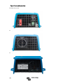
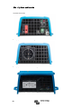
Fig 1: Front and rear view
FigFi
Example of front view:
Example of rear view with Schuko outlet:
Example of rear view with NEMA GFCI outlet:

11
EN NO SV
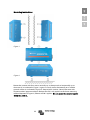
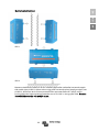
Mounting instructions
Figure 1
Figure 2
Mount the inverter with four screws vertically up- or downwards or horizontally up- or
downwards (as indicated in Figure 1) against a sturdy wall or horizontally on a suitable
ground surface (as indicated in Figure 2). Keep at least 4 inches (10 cm) clearance with
respect to other apparatus/objects. Beware that IP21 only applies to the lower mounting
method depicted in Figure 2; otherwise IP20 is applies. Do not mount the inverter upside
down to a surface.

12
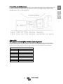
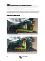
Appendix A
Connecting the inverter neutral output to the chassis/ground
The AC output is isolated from the DC input and the chassis. Local regulations may require a true neutral.
In this case one of the AC output wires must be connected to the chassis, and the chassis must be
connected to a reliable ground. Inside the inverter a provision has been made to be able to connect the
neural and the chassis; the way to do this is explained below.
Please be sure to disconnect the battery when connecting the neutral to protective earth (PE).
An internal PE wire, which is used to connect the neutral and the chassis, is accessible after removing the
plastic cover. A Torx T10 screwdriver is needed to loosen the four screws which hold the plastic cover.
In the pictures below the two possible connections of the PE wire are shown:
For the 250 VA, 375 VA and 500 VA inverters:
1. Neutral floating
Position of the PE wire (indicated by arrow):
2. Neutral connected to protective earth
Position of the PE wire (indicated by arrow):

13
EN NO SV
For the 800 VA and 1200 VA inverters:
For these inverters the earth wire from the chassis can be either connected to FJ1 (neutral floating) or to
FJ2 (neutral connected to earth/chassis). The labels FJ1 and FJ2 are printed on the circuit board. The
default position is FJ1, i.e. neutral is floating.
Appendix B
Wire size for connecting the inverter chassis to ground
The earth conductor from the earth lug on the chassis to ground should have at least half the cross-
section of the conductors used for the battery connection. The maximum conductor size that fits the
earth lug is 25 mm². Use the table below to find the correct cross-section for the earth conductor.
Cable cross-section
to battery
to protective earth
1.5 mm²
≥ 0.75 mm²
2.5 mm²
≥ 1.5 mm²
4 mm²
≥ 2.5 mm²
6 mm²
≥ 4 mm²
10 mm²
≥ 6 mm²
16 mm²
≥ 10 mm²
25 mm²
≥ 16 mm²
35 mm²
25 mm²


1
EN NO SV
1. VIKTIGE SIKKERHETSINSTRUKSJONER – TA VARE PÅ
DISSE INSTRUKSJONER!
Generelt
Les alltid dokumentasjonen som leveres med produktet og bli kjent med sikkerhetsskiltene og
anvisningene før produktet tas i bruk.
Produktet er utviklet og testet i samsvar med internasjonale standarder. Utstyret skal kun brukes for den
angitte applikasjonen.
Advarsel – Serviceinstruksjonene skal kun brukes av kvalifisert
personell. Reduser risikoen for elektrisk støt ved aldri å utføre annet
enn det som er spesifisert i bruksanvisningen, med mindre du er
kvalifisert til det.
ADVARSEL: ELEKTRISK STØTFARE
Produktet vil brukes sammen med en permanent energikilde (batteri). Inngangs- og/eller
utgangsterminaler kan fremdeles være under farlig spenning, selv når utstyret vil slås av. Batteriet må
alltid frakobles før produktet vedlikeholdes eller finnes under service.
Produktet har ingen interne komponenter som kan repareres av brukere. Fjern aldri frontplaten eller
bruk aldri produktet etter fjerning av noen paneler. Service må kun utføres av kvalifisert personell.
Les installasjonsinstruksjonene som finnes i installasjonshåndboken før utstyret installeres.
Dette er et sikkerhetsprodukt i klasse I (leveres med en beskyttende jordingsterminal). Chassiset må
være jordet. Et jordingspunkt finnes på utsiden av produktet. Hvis du mistenker at jordingsbeskyttelsen
er skadet, må produktet slås av og sikres mot utilsiktet bruk; kontakt kvalifisert servicepersonell
umiddelbart.
Den alternative strømutgangen er isolert fra likestrøminngangen og chassiset med mindre enheten
kommer med en jordfeilbryter. Vekselstrømutgang fra enheter som kommer med jordfeilbryter er
koblet nøytral til chassiset inne i enheten som standard. En kvalifisert installatør må sjekke
tilkoblingen og bekrefte at jordfeilbryteren fungerer som den skal. Lokale forskrifter kan kreve en ekte
nøytral. Derfor må en av de AC-utgangstrådene kobles til chassiset, og chassiset kobles til en pålitelig
jord. Merk at en ekte nøytral kreves med det formål å sikre riktig bruk av en jordfeilbryter.
Bekreft at utstyret brukes under rette omgivelsesforhold.
Bruk aldri produktet i et vått eller støvete miljø.
Bruk aldri produktet i omgivelser der det er fare for gass- eller støveksplosjoner.
Bekreft at det er tilstrekkelig ledig plass (10 cm) for ventilasjon rundt produktet, og bekreft at
ventilasjonsåpningene er ikke blokkert.
Enheten skal aldri brukes av personer (inkludert barn) med reduserte fysiske,
sensoriske eller mentale evner eller uten erfaring og kunnskap, med mindre de har fått tilsyn
eller instruksjon om bruk av enheten av en person som er ansvarlig for
deres sikkerhet.
Barn bør overvåkes med det formål å sikre at de ikke leker med apparatet.
Hvis du bruker et tilbehør som ikke er anbefalt eller solgt av produsenten, kan dette resultere i fare for
brann, elektrisk støt eller personskade.

2
2. Beskrivelse
VE.Direct-kommunikasjonsport
VE.Direct-porten kan kobles til:
• En datamaskin (VE.Direct til USB-grensesnittkabel er nødvendig)
• Apple- og Android-smarttelefoner, nettbrett og andre enheter (VE.Direct til Bluetooth Smart dongle
er nødvendig)
Kan konfigureres
• Alarm for lavt batterispenning og tilbakestillingsnivåer
• Avbryt ved lav batterispenning og tilbakestillingsnivåer, eller dynamisk avbrytelse
• Utgangsspenning 210 - 245 V
• Frekvens 50 Hz eller 60 Hz
• ØKO-modus av/på og følelsesnivå for ØKO-modus
Overvåking
Batterispenning, AC-utgangsspenning, belastningsindikator, alarmer
Bevist pålitelighet
Hele broen med topologi for toroidal transformator har bevist sin pålitelighet gjennom mange år.
Vekselrettere er kortslutningssikre og beskyttet mot overoppheting, enten det skyldes overbelastning
eller høy omgivelsestemperatur.
Høy oppstartkraft
Kreves for å starte belastninger som strømomformere for LED-lamper, glødelamper eller elektrisk
verktøy.
ØKO-modus
I ØKO-modus, vil vekselretteren gå i standby når belastningen er under en forhåndsinnstilt verdi. Den vil
slås på og sjekke hvert par sekunder, justerbar, om belastning har økt igjen.
Ekstern av/på-bryter
En ekstern av/på-bryter kan kobles til en kontakt med to poler eller mellom batteri plussiden og den
venstre kontakten til kontakt med to poler.
Diagnose med LED
En rød og en grønn LED indikerer betjening av vekselretteren og status for de forskjellige beskyttelsene.
Slik overfører du belastningen til en annen vekselstrømskilde: den automatiske overføringsbryteren
Vi anbefaler Filax automatisk overføringsbryter for våre vekselrettere med lav effekt. Filax kommer med
en veldig kort omstillingstid (mindre enn 20 millisekunder), slik at datamaskiner og annet elektronisk
utstyr fortsetter å fungere uten forstyrrelser.
Kommer med forskjellige utgangskontakter
Schuko, UK (BS-1363), AU/NZ (3112) eller IEC-320 (hannplugg inkludert)

3
EN NO SV
3. Installasjon
3.1 Plassering av vekselretteren
1
Takmontering (omvendt).
Anbefales ikke
2.
Montering på sokkel.
OK
3
Vertikal veggmontering, vifte i
bunnen.
OK (vær oppmerksom på små gjenstander som faller
gjennom ventilasjonsåpningene som finnes på
toppen).
4
Vertikal veggmontering, vifte på
toppen.
Anbefales ikke
5
Horisontal veggmontering.
OK
For best mulig driftsresultat, bør vekselretteren plasseres på en flat overflate. Sikre en problemfri drift av
vekselretteren ved å bruke den på steder som oppfyller følgende krav:
d) Unngå kontakt med vann. Utsett aldri vekselretteren for regn eller fuktighet.
e) Plasser aldri enheten i direkte sollys. Omgivelsestemperaturen skal være mellom
-20 °C og 40 °C (fuktighet < 95 % uten kondens). Merk at i ekstreme situasjoner, kan
temperaturen på den ytre siden av vekselretteren overstige 70 °C.
f) Luftstrømmen rundt vekselretteren må aldri hindres. La det være en avstand på minst 10
centimeter
rundt vekselretteren. Når vekselretteren er for varmt, vil den slå seg av. Når vekselretteren har
nådd et sikkert temperaturnivå, vil enheten starte automatisk på nytt.

4
3.2 Tilkobling til batteriet
Utnytt produktets fulle kapasitet ved å bruke batterier med tilstrekkelig kapasitet og batterikabler med
tilstrekkelig tverrsnitt. Se tabell:
12/250
24/250
48/250
12/375
24/375
48/375
Minimum
batterikap.
30 Ah 20 Ah 10 Ah 40 Ah 30 Ah 15 Ah
Intern DC-sikring 2 x 30 A 30 A 25 A 2 x 40 A 40 A 25 A
Sikringstype (Mfr.:
Littelfuse)
ATOF
32 V
ATOF
32 V
FKS
80 V
ATOF
32 V
ATOF
32 V
FKS
80 V
Sikring kan skiftes
ut
nei nei nei nei nei nei
Anbefalt tverrsnitt av likestrømkabel (mm2)
0 – 1,5 m
4 mm²
2,5 mm²
1,5 mm²
6 mm²
4 mm²
2,5 mm²
1,5 – 3 m 6 mm² 4 mm² 2,5 mm² 10 mm² 6 mm² 4 mm²
12/500
24/500
48/500
12/800
24/800
48/800
Minimum batterikap.
60 Ah
40 Ah
20 Ah
100 Ah
50 Ah
30 Ah
Intern DC-sikring
3 x 35 A
2 x 25 A
30 A
125 A
2 x 40 A
2 x 20 A
Sikringstype (Mfr.:
Littelfuse)
ATOF
32 V
ATOF
32 V
FKS
80 V
MIDI
32 V
ATOF
32 V
FKS
80 V
Sikring kan skiftes ut
nei
nei
nei
ja
nei
nei
Anbefalt tverrsnitt av likestrømkabel (mm2)
0 – 1,5 m
6 mm²
6 mm²
4 mm²
16 mm²
6 mm²
4 mm²
1,5 -3 m
10 mm²
10 mm²
6 mm²
25 mm²
10 mm²
6 mm²
12/1200
24/1200
48/1200
Minimum batterikap.
150 Ah
60 Ah
30 Ah
Intern DC-sikring
200 A
100 A
50 A
Sikringstype (Mfr.:
Littelfuse)
MIDI
32 V
MIDI
32 V
MIDI
58 V
Sikring kan skiftes ut
ja
ja
ja
0 – 1,5 m 25 mm² 10 mm² 6 mm²
1,5 -3 m
35 mm²
16 mm²
10 mm²
Vekselretterne har en intern likestrømsikring (se tabellen ovenfor). Hvis lengden på likestrømskabelen
økes til mer enn 1,5 m, er vår anbefaling å bruke en ekstra sikring eller likestrømbryter i nærheten av
batteriet. Viktig merknad: for UL-sertifiserte (NEMA GFCI) vekselrettere må det alltid installeres en sikring
eller likestrømbryter nær batteriet, selv om kabellengden er mindre enn 1,5 m.
Omvendt polaritetstilkobling av batteritrådene kan føre til blåsing av den interne sikringen og kan skade
vekselretteren. Den interne sikringen kan ikke alltid byttes ut (se tabellen over).
3.3 Ledningsstørrelse for tilkobling av vekselretterens chassis til bakken
Jordleder fra jordklemmen på chassiset til jorden skal minst ha halvparten av tverrsnittet av lederne som
brukes til batteritilkoblingen: se vedlegg B.
3.4 Tilkobling til belastning
Koble aldri vekselretterens utgangen til en annen alternativ strømkilde, for eksempel et kjent stikkontakt
eller en generator.
Vekselretteren har ingen sikring i alternativ strømutgang. Den alternative strømkabelen kommer
beskyttet av en hurtigvirkende strømbegrenser ved kortslutning og en mekaniske for deteksjon av
overbelastning som etterligner egenskapene til en sikring (slik som raskere avstengning med større
overbelastning). Riktig dimensjonering av ledningene dine basert på rekselretterens effekt anses å være
viktig.

5
EN NO SV
3.5 Tilkobling av vekselretterens nøytrale utgang til chassiset/jorden
AC-utgangen er isolert fra DC-inngangen og chassiset. Lokale forskrifter kan kreve en ekte nøytral. Derfor
må en av AC-utgangstrådene kobles til chassiset, og chassiset kobles til en pålitelig jord: se vedlegg A.
3.6 Ekstern av/på-bryter
En ekstern av/på-bryter kan kobles til kontakten med to poler. Koblingskontakten til venstre kan skiftes
til batteriets positive side: nyttig i billapplikasjoner, koble ledninger til tenningskontakten.
Merk at frontbryteren må også stille på enten På eller ØKO slik at vekselretteren kan starte.
3.7 Konfigurasjon
Vekselretteren kan nå brukes med fabrikkinnstillingene (se spesifikasjoner), og kan konfigureres med en
datamaskin (VE.Direct to USB-grensesnittkabel er nødvendig), Apple- og Android-smarttelefoner,
nettbrett og andre enheter (VE.Direct to Bluetooth Smart dongle er nødvendig).
Sidan laddas...
Sidan laddas...
Sidan laddas...
Sidan laddas...
Sidan laddas...
Sidan laddas...
Sidan laddas...
Sidan laddas...
Sidan laddas...
Sidan laddas...
Sidan laddas...
Sidan laddas...
Sidan laddas...
Sidan laddas...
Sidan laddas...
Sidan laddas...
Sidan laddas...
Sidan laddas...
Sidan laddas...
Sidan laddas...
Sidan laddas...
Sidan laddas...
Sidan laddas...
-
 1
1
-
 2
2
-
 3
3
-
 4
4
-
 5
5
-
 6
6
-
 7
7
-
 8
8
-
 9
9
-
 10
10
-
 11
11
-
 12
12
-
 13
13
-
 14
14
-
 15
15
-
 16
16
-
 17
17
-
 18
18
-
 19
19
-
 20
20
-
 21
21
-
 22
22
-
 23
23
-
 24
24
-
 25
25
-
 26
26
-
 27
27
-
 28
28
-
 29
29
-
 30
30
-
 31
31
-
 32
32
-
 33
33
-
 34
34
-
 35
35
-
 36
36
-
 37
37
-
 38
38
-
 39
39
-
 40
40
-
 41
41
-
 42
42
-
 43
43


Victron energy 12-250 Användarmanual
- Kategori
- Nätadaptrar
- Typ
- Användarmanual
på andra språk
- English: Victron energy 12-250 User manual
- dansk: Victron energy 12-250 Brugermanual
Relaterade papper
-
Victron energy Phoenix Inverter Smart 1600VA - 5000VA Bruksanvisning
-
-
-
-
-
-
-
