Victron energy Inverter 3k 5k 230V Bruksanvisning
- Typ
- Bruksanvisning

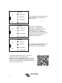
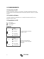
Manual
EN
Handleiding
NL
Manuel
FR
Anleitung
DE
Manual
ES
Användarhandbok
SE
Manuale
IT
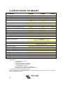
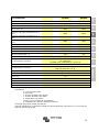
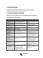
Appendix
Inverter (with firmware xxxx400 or higher)
12 | 3000 | 230V 24 | 3000 | 230V 48 | 3000 | 230V
24 | 5000 | 230V 48 | 5000 | 230V

2

3
EN
NL
FR
DE
ES
SE
IT
Appendix
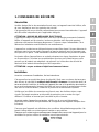
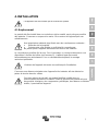
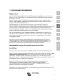
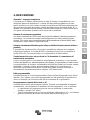
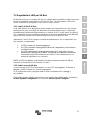
1. SAFETY INSTRUCTIONS
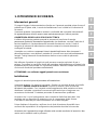
In general
Please read the documentation supplied with this product first, so that you are familiar
with the safety signs en directions before using the product.
This product is designed and tested in accordance with international standards. The
equipment should be used for the designated application only.
WARNING: DANGER OF ELECTRICAL SHOCK
The product is used in combination with a permanent energy source (battery). Even if
the equipment is switched off, a dangerous electrical voltage can occur at the input
and/or output terminals. Always switch the AC power off and disconnect the battery
before performing maintenance.
The product contains no internal user-serviceable parts. Do not remove the front panel
and do not put the product into operation unless all panels are fitted. All maintenance
should be performed by qualified personnel.
Never use the product at sites where gas or dust explosions could occur. Refer to the
specifications provided by the manufacturer of the battery to ensure that the battery is
suitable for use with this product. The battery manufacturer's safety instructions
should always be observed.
WARNING: do not lift heavy objects unassisted.
Installation
Read the installation instructions before commencing installation activities.
This product is a safety class I device (supplied with a ground terminal for safety
purposes). The chassis must be grounded. A grounding point is located on the
outside of the product. If it can be assumed that the grounding protection is damaged,
the product should be taken out of operation and prevented from accidentally being
put into operation again; contact qualified maintenance personnel.
Ensure that the connection cables are provided with fuses and circuit breakers. Never
replace a protective device by a component of a different type. Refer to the manual for
the correct part.
Check before switching the device on whether the available voltage source conforms
to the configuration settings of the product as described in the manual.
Ensure that the equipment is used under the correct operating conditions. Never
operate it in a wet or dusty environment.
Ensure that there is always sufficient free space around the product for ventilation,
and that ventilation openings are not blocked.

4
Install the product in a heatproof environment. Ensure therefore that there are no
chemicals, plastic parts, curtains or other textiles, etc. in the immediate vicinity of the
equipment.
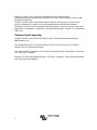
Transport and storage
On storage or transport of the product, ensure that the battery leads are disconnected.
No liability can be accepted for damage in transit if the equipment is not transported in
its original packaging.
Store the product in a dry environment; the storage temperature should range from
–20°C to 60°C.
Refer to the battery manufacturer's manual for information on transport, storage,
charging, recharging and disposal of the battery.

5
EN
NL
FR
DE
ES
SE
IT
Appendix
2. DESCRIPTION
SinusMax - Superior engineering
Developed for professional duty, the range of inverters is suitable for the widest range
of applications. The design criteria have been to produce a true sine wave inverter
with optimised efficiency but without compromise in performance. Employing hybrid
HF technology, the result is a top quality product with compact dimensions, light in
weight and capable of supplying power, problem-free, to any load.
Extra start-up power
A unique feature of the SinusMax technology is very high start-up power.
Conventional high frequency technology does not offer such extreme performance.
These inverters, however, are well suited to power up difficult loads such as
compressors, electric motors and similar appliances.
Virtually unlimited power thanks to parallel and 3-phase operation capability
Up to 6 inverters can operate in parallel to achieve higher power output. Six 24/5000
units, for example, will provide 30 kVA output power. Operation in 3-phase
configuration is also possible.
To transfer the load to another AC source: the automatic transfer switch
If an automatic transfer switch is required, we recommend to using the MultiPlus or
Quattro instead. The switch is included in these products and the charger function of
the MultiPlus/Quattro can be disabled. Computers and other electronic equipment will
continue to operate without disruption because the MultiPlus/Quattro features a very
short switchover time (less than 20 milliseconds).
Programmable relay
The Inverter is equipped with a programmable relay, which by default is set as an
alarm relay. The relay can be programmed for all kinds of other applications however,
for example as a starter relay for a generating set.
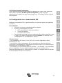
Programmable with DIP switches or personal computer
The Inverter is supplied ready for use. The following features are available for
changing certain settings if desired:
─ The most important settings can be changed in a very simple manner, using DIP
switches.
─ All settings can be changed with a PC and free of charge software,
downloadable from our website www.victronenergy.com

6
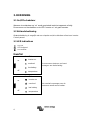
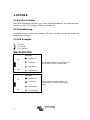
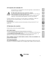
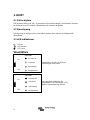
3. OPERATION
3.1 On/Off Switch
When switched to "on", the product is fully functional. The inverter will come into
operation and the LED "inverter on" will light up.
3.2 Remote control
Remote control is possible with a simple on/off switch or with a Inverter Control panel.
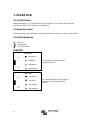
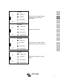
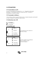
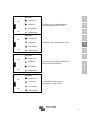
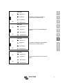
3.3 LED Indications
LED off
LED flashes
LED illuminated
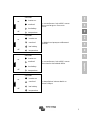
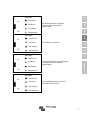
Inverter
inverter
The inverter is on and supplies
power to the load.
on
inverter on
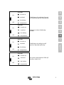
overload
low battery
off
temperature
inverter
The nominal output of the inverter is
exceeded. The “overload” LED
flashes.
on
inverter on
overload
low battery
off
temperature

7
EN
NL
FR
DE
ES
SE
IT
Appendix
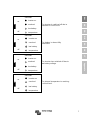
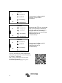
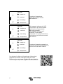
inverter
The inverter is switched off due to
overload or short circuit.
on
inverter on
overload
low battery
off
temperature
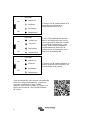
inverter
The battery is almost fully
exhausted.
on
inverter on
overload
low battery
off
temperature
inverter
The inverter has switched off due to
low battery voltage.
on
inverter on
overload
low battery
off
temperature
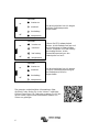
inverter
The internal temperature is reaching
a critical level.
on
inverter on
overload
low battery
off
temperature

8
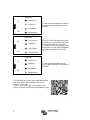
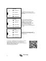
inverter
The inverter has switched off due to
the electronics temperature being
too high.
on
inverter on
overload
low battery
off
temperature
inverter
-If the LEDs are flashing alternately,
the battery is nearly exhausted and
the nominal output is exceeded.
-If "overload" and "low battery" flash
simultaneously, the ripple voltage on
the battery terminals is too high.
on
inverter on
overload
low battery
off
temperature
inverter
The inverter switched off due to
excess ripple voltage on the battery
terminals.
on
inverter on
overload
low battery
off
temperature
For the latest and most up to date information
about the blink codes, please refer to the
Victron Toolkit app.
Click on or scan the QR code to get to the
Victron Support and Downloads/Software page.

9
EN
NL
FR
DE
ES
SE
IT
Appendix
4. INSTALLATION
This product may only be installed by a qualified electrical engineer.
4.1 Location
The product must be installed in a dry and well-ventilated area, as close as possible to
the batteries. There should be a clear space of at least 10 cm around the appliance for
cooling.
Excessively high ambient temperature will result in the following:
• Reduced service life.
• Reduced peak capacity, or shutdown of the inverter.
Never position the appliance directly above the batteries.
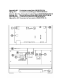
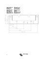
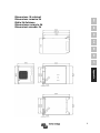
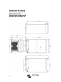
The Inverter is suitable for wall mounting. For mounting purposes, a hook and two
holes are provided at the back of the casing (see appendix G). The device can be
fitted either horizontally or vertically. For optimal cooling, vertical fitting is preferred.
The interior of the product must remain accessible after installation.
Try to keep the distance between the product and the battery to a minimum in order to
minimize cable voltage losses.
For safety purposes, this product should be installed in a heat-resistant
environment. You should prevent the presence of e.g. chemicals, synthetic
components, curtains or other textiles, etc., in the immediate vicinity.

10
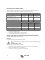
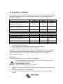
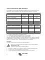
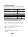
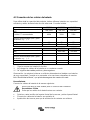
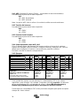
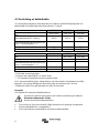
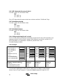
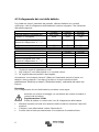
4.2 Connection of battery cables
In order to utilize the full capacity of the product, batteries with sufficient capacity and
battery cables with sufficient cross section should be used. See table.
12/3000
24/3000
48/3000
Recommended battery capacity (Ah)
400–1200
200–700
100–400
Recommended DC fuse
400A
300A
125A
Recommended cross-section (mm2)
per + and - connection terminal *, **
0 – 5 m
90
50
35
5 – 10 m
120
90
70
24/5000
48/5000
Recommended battery capacity (Ah)
400–1400
200–800
Recommended DC fuse
400A
200A
Recommended cross-section (mm2)
per + and - connection terminal *, **
0 – 5 m***
2x 50 mm2
1x 70 mm2
5 -10 m***
2x 90 mm2
2x 70 mm2
* Follow local installation rules.
** Do not locate battery cables in a closed conduit.
*** “2x” means two positive and two negative cables.
Remark: Internal resistance is the important factor when working with low capacity
batteries. Please consult your supplier or the relevant sections of our book “electricity
on board”, downloadable from our website.
Procedure
Proceed as follows to connect the battery cables:
Use a torque wrench with insulated box spanner in order to avoid shorting the
battery.
Maximum torque: 11 Nm
Avoid shorting the battery cables.
• Undo the four screws at the front of the enclosure and remove the front panel.
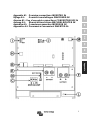
• Connect the battery cables: see Appendix A.
• Tighten the nuts well for minimal contact resistance.

11
EN
NL
FR
DE
ES
SE
IT
Appendix
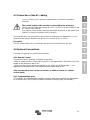
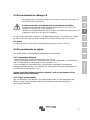
4.3 Connection of the AC cabling
This is a Safety Class I product (supplied with a protective grounding
terminal).
The neutral output of the inverter is connected to the enclusure.
This to ensure proper functioning of a GFCI (or RCCB) to be installed in the
AC output of the Inverter.
The chassis of the product must be connected to ground, or the frame (of a
vehicle) or the ground plate or hull (of a boat).
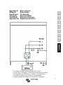
The terminal block can be found on the printed circuit board, see Appendix A. Use a
three-wire cable with a flexible core and a cross section of 2.5 or 4 mm²
Procedure
The AC output cable can be connected directly to the terminal block "AC-out".
4.4 Optional Connections
A number of optional connections are possible:
4.4.1 Remote Control
The product can be remotely controlled in two ways.
- With an external switch (connection terminal H, see appendix A). Operates only if the
switch on the Inverter is set to “on”.
- With a Inverter Control panel (connected to one of the two RJ48 sockets C, see
appendix A). Operates only if the switch on the inverter is set to “on”.
Only one remote control can be connected, i.e. either a switch or a remote
control panel.
4.4.2. Programmable relay
The inverters are equipped with a multi-functional relay that by default is programmed
as an alarm relay. (VEConfigure software needed to change relay functionality).

12
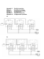
4.4.3 Parallel Connection
The Inverter can be connected in parallel with several identical devices. To this end, a
connection is established between the devices by means of standard RJ45 UTP
cables. The system (Two or more Inverters plus optional control panel) will require
subsequent configuration (see Section 5).
In the event of connecting units in parallel, the following requirements must be met:
• A maximum of six units connected in parallel.
• Only identical devices with the same power ratings may be connected in parallel.
• Battery capacity should be sufficient.
• The DC connection cables to the devices must be of equal length and cross-
section.
• If a positive and a negative DC distribution point is used, the cross-section of the
connection between the batteries and the DC distribution point must at least
equal the sum of the required cross-sections of the connections between the
distribution point and the Inverter units.
• Place the units close to each other, but allow at least 10 cm for ventilation
purposes under, above and beside the units.
• UTP cables must be connected directly from one unit to the other (and to the
remote panel). Connection/splitter boxes are not permitted.
• Only one remote control means (panel or switch) can be connected to the
system.
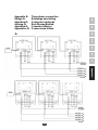
4.4.4 Three-phase operation
The Inverter can also be used in 3-phase wye (Y) configuration. To this end, a
connection between the devices is made by means of standard RJ45 UTP cables (the
same as for parallel operation). The system (Inverters plus an optional control panel)
will require subsequently configuration (see Section 5).
Pre-requisites: see Section 4.4.3.
Note: the Inverter is not suitable for 3-phase delta (Δ) configuration.

13
EN
NL
FR
DE
ES
SE
IT
Appendix
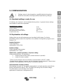
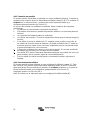
5. CONFIGURATION
• Settings may only be changed by a qualified electrical engineer.
• Read the instructions thoroughly before implementing changes.
5.1 Standard settings: ready for use
On delivery, the Inverter is set to standard factory values. In general, these settings
are suitable fo stand-alone operation.
Standard factory settings
Inverter frequency 50 Hz
Inverter voltage 230 VAC
Stand-alone / parallel / 3-phase stand-alone
AES (Automatic Economy Switch) off
Programmable relay alarm function
5.2 Explanation of settings
Settings that are not self-explanatory are described briefly below. For further
information, please refer to the help files in the software configuration programs (see
Section 5.3).
Inverter frequency
Output frequency
Adjustability: 50Hz; 60Hz
Inverter voltage
Output voltage of the Inverter.
Adjustability: 210 – 245V
Stand-alone / parallel operation / 2-3 phase setting
Using several devices, it is possible to:
• increase total inverter power (several devices in parallel)
• create a 3-phase system.
To this end, the devices must be mutually connected with RJ45 UTP cables.
Standard device settings, however, are such that each device operates in stand-alone
operation. Reconfiguration of the devices is therefore required.
AES (Automatic Economy Switch)
If this setting is turned ‘on’, the power consumption in no-load operation and with low
loads is decreased by approx. 20%, by slightly 'narrowing' the sinusoidal voltage.
The AES Mode can be set with a DIP switch.
Applicable in stand-alone configuration only.

14
Search Mode (Applicable in stand-alone configuration only)
If search mode is ‘on’, the power consumption in no-load operation is decreased by
approx. 70%. In this mode the inverter is switched off in case of no load or very low
load, and switches on every two seconds for a short period. If the output current
exceeds a set level, the inverter will continue to operate. If not, the inverter will shut
down again.
Not adjustable with DIP switches.
The Search Mode “shut down” and “remain on” load levels can be set with
VEConfigure.
The standard settings are:
Shut down: 40 Watt (linear load)
Turn on: 100 Watt (linear load)
Programmable relay
By default, the programmable relay is set as an alarm relay, i.e. the relay will de-
energise in the event of an alarm or a pre-alarm (inverter almost too hot, ripple on the
input almost too high, battery voltage almost too low). Not adjustable with DIP
switches.
5.3 Configuration by computer
All settings can be changed by means of a computer.
The most common settings can be changed by means of DIP switches (see Section
5.5).
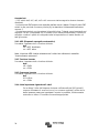
NOTE:
This manual is intended for products with firmware xxxx400 or higher (with x
any number)
The firmware number can be found on the microprocessor, after removing the
front panel.
It is possible to update older units, as long as that same 7 digit number starts with
either 26 or 27. When it starts with 19 or 20 you have an old microprocessor and it is
not possible to update to 400 or higher.
For changing settings with the computer, the following is required:
• VEConfigure3 software: can be downloaded free of charge at
www.victronenergy.com.
• A MK3-USB (VE.Bus to USB) interface.
Alternatively, the Interface MK2.2b (VE.Bus to RS232) can be used (RJ45 UTP
cable needed).

15
EN
NL
FR
DE
ES
SE
IT
Appendix
5.3.1 VE.Bus Quick Configure Setup
VE.Bus Quick Configure Setup is a software program with which systems with a
maximum of three Inverters (parallel or three phase operation) can be configured in a
simple manner. VEConfigure3 forms part of this program.
You can download the software free of charge at www.victronenergy.com .
5.3.2 VE.Bus System Configurator
For configuring advanced applications and/or systems with four or more Inverters,
VE.Bus System Configurator software must be used. You can download the
software at www.victronenergy.com . VEConfigure3 forms part of this program.
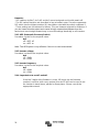
5.4 Configuration with DIP switches
A number of settings can be changed using DIP switches (see appendix A, position I).
Procedure:
• Turn the Inverter on, preferably unloaded.
• Set the DIP switches for:
o AES (Automatic Economy Switch)
o Inverter voltage
o Inverter frequency
• To store the settings after the required values have been set: press the 'Up'
button for 2 seconds (upper button to the right of the DIP switches, see
appendix A, position J).

16
Remarks:
- DIP switches ds8,ds7 ,ds6 ,ds2 and ds1 are not assigned and should remain off.
- The DIP switch functions are described in 'top to bottom' order. Since the uppermost
DIP switch has the highest number (8), descriptions start with the switch numbered 5.
- These settings are not relevant for slaves. They are however relevant for followers. If
you don’t want to bother about an Inverter being a master/slave/follower then the
easiest and most straight forward way is to set all settings identically on all Inverters.
5.4.1 AES (Automatic Economy Switch)
Procedure: set ds5 to the required value:
ds5
off = AES off
on = AES on
Note: The AES option is only effective if the unit is used ‘stand alone’.
5.4.2 Inverter voltage
Procedure: set ds4 to the required value:
ds4
off = 240V
on = 230V
5.4.3 Inverter frequency
Procedure: set ds3 to the required value:
ds3
off = 60Hz
on = 50Hz
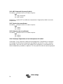
5.4.4. Important note on ds2 and ds1
If the last 3 digits of the firmware is in the 100 range (so the firmware
number is xxxx1xx (with x any number) then ds1 & ds2 can be used to set
the inverter in stand-alone, parallel or three-phase. Please consult the
appropriate manual.

17
EN
NL
FR
DE
ES
SE
IT
Appendix
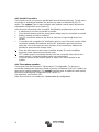
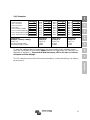
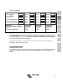
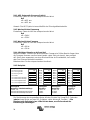
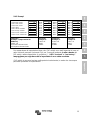
5.4.5 Examples
DS-8 not used
off
DS-7 not used
off
DS-6 not used
off
DS-5 AES
off
DS-4 Inverter voltage
on
DS-3 Inverter frequency
on
DS-2 Stand-alone mode
off
DS-1 Stand-alone mode
off
DS-8
off
DS-7
off
DS-6
off
DS-5
off
DS-4
off
DS-3
off
DS-2
off
DS-1
off
DS-8
off
DS-7
off
DS-6
off
DS-5
off
DS-4
on
DS-3
off
DS-2
off
DS-1
off
DS-8
off
DS-7
off
DS-6
off
DS-5
on
DS-4
off
DS-3
on
DS-2
off
DS-1
off
stand-alone
Example 1 (factory setting):
5 AES: off
4 Inverter voltage 230V
3 Inverter frequency 50Hz
stand-alone
Example 2:
5 AES: off
4 240V
3 60Hz
stand-alone
Example 3:
5 AES: off
4 230V
3 60Hz
stand-alone
Example 4:
5 AES: on
4 240V
3 50Hz
To store the settings after the dipswitches are set according to the required values:
press the 'Up' button for 2 seconds (upper button to the right of the DIP switches, see
appendix A, position J). The overload and low-battery LED’s will flash to indicate
acceptance of the settings.
The DIP switches can be left in the selected positions, so that the settings can always
be recovered.

18
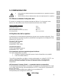
6. MAINTENANCE
The Inverter does not require specific maintenance. It will suffice to check all
connections once a year. Avoid moisture and oil/soot/vapours, and keep the device
clean.
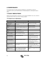
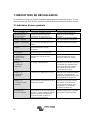
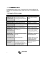
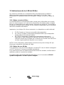
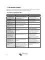
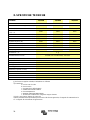
7. FAULT INDICATIONS
With the procedures below, most errors can be quickly identified. If an error cannot be
resolved, please refer to your Victron Energy supplier.
7.1 General error indications
Problem
Cause
Solution
Inverter operation not
initiated when
switched on.
The battery voltage is excessively
high or too low. No voltage on DC
connection.
Ensure that the battery voltage is
within the correct range.
“Low battery” LED
flashes.
The battery voltage is low.
Charge the battery or check the
battery connections.
“Low battery” LED
lights.
The converter switches off
because the battery voltage is too
low.
Charge the battery or check the
battery connections.
“Overload” LED
flashes.
The converter load is higher than
the nominal load.
Reduce the load.
“Overload” LED
lights.
The converter is switched off due
to excessively high load.
Reduce the load.
“Temperature” LED
flashes or lights.
The environmental temperature is
high, or the load is too high.
Install the converter in cool and
well-ventilated environment, or
reduce the load.
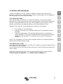
“Low battery” and
“overload” LEDs
flash intermittently.
Low battery voltage and
excessively high load.
Charge the batteries, disconnect
or reduce the load, or install
higher capacity batteries. Fit
shorter and/or thicker battery
cables.
“Low battery” and
“overload” LEDs
flash simultaneously.
Ripple voltage on the DC
connection exceeds 1,5Vrms.
Check the battery cables and
battery connections. Check
whether battery capacity is
sufficiently high, and increase
this if necessary.
“Low battery” and
“overload” LEDs
light.
The inverter is switched off due to
an excessively high ripple voltage
on the input.
Install batteries with a larger
capacity. Fit shorter and/or
thicker battery cables, and reset
the inverter (switch off, and then
on again).
One alarm LED lights
and the second
flashes.
The inverter is switched off due to
alarm activation by the lighted
LED. The flashing LED indicates
that the inverter was about to
switch off due to the related alarm.
Check this table for appropriate
measures in regard to this alarm
state.

19
EN
NL
FR
DE
ES
SE
IT
Appendix
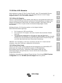
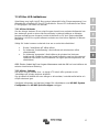
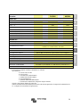
7.2 VE.Bus LED indications
Inverters included in a VE.Bus system (a parallel or 3-phase arrangement) can
provide so-called VE.Bus LED indications. These LED indications can be subdivided
into two groups: OK codes and error codes.
7.2.1 VE.Bus OK codes
If the internal status of a device is in order but the device cannot yet be started
because one or more other devices in the system indicate an error status, the devices
that are in order will indicate an OK code. This facilitates error tracing in a VE.Bus
system, since devices not requiring attention are easily identified as such.
Important: OK codes will only be displayed if a device is not inverting!
• The "inverter on" LED must flash.
• A flashing "overload" LED indicates that the device can perform inverter
operation.
• A flashing "temperature" LED indicates that the device is not blocking
charge operation. (This is just a formal indication which originates from the
relationship with the Multi. This indication has no special meaning on a
Inverter)
NOTE: The "low battery" LED can function together with the OK code that indicates
that the device does not block charge.
7.2.2 VE.Bus error codes
If a VE.Bus error occurs (example: a broken UTP cable) the system will switch off and
the ‘inverter on’ LED will flash.
If such an error occurs one should switch all units off, verify all cabling and switch the
units on again.
Additional information about the errror can be retrieved from the Inverter with the
VE.BUS System Configurator or the VE.BUS Quick Configure tool.

20
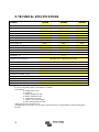
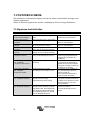
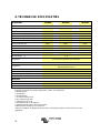
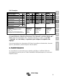
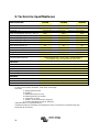
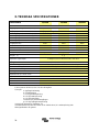
8. TECHNICAL SPECIFICATIONS
Inverter
12/3000
24/3000
48/3000
INVERTER
Input voltage range (V DC)
9,5 – 17
19 – 33
38 – 66
Output (1)
Output voltage: 230 VAC ± 2% Frequency: 50 Hz ± 0,1%
Cont. output power at 25°C (VA) (3)
3000
3000
3000
Cont. output power at 25°C (W)
2400
2400
2400
Cont. output power at 40°C (W)
2200
2200
2200
Cont. output power at 65°C (W)
1700
1700
1700
Peak power (W)
6000
6000
6000
Maximum efficiency (%)
92
94
95
Zero-load power (W)
20
20
25
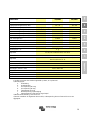
GENERAL
Programmable relay (4)
Yes
Yes
Yes
Protection (2)
a – g
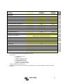
Common Characteristics
Operating temp.: -40 to +65°C (fan assisted cooling)
Humidity (non condensing): max 95%
ENCLOSURE
Common Characteristics
Material & Colour: aluminium (blue RAL 5012) Protection: IP 21
Battery-connection
M8 bolts (2 plus and 2 minus connections)
230 V AC-connection
Screw terminals 13mm² (6 AWG)
Weight (kg)
18
Dimensions (hxwxd in mm)
362x258x218
STANDARDS
Safety
EN 60335-1, EN 60335-2-29
Emission / Immunity
EN 55014-1, EN 61000-3-2 / EN 55014-2, EN 61000-3-3
Automotive Directive
2004/104/EC
1) Can be adjusted to 60Hz; 120V/60Hz on request
2) Protection
a. Output short circuit
b. Overload
c. Battery voltage too high
d. Battery voltage too low
e. Temperature too high
f. 230VAC on inverter output
g. Input voltage ripple too high
3) Non linear load, crest factor 3:1
4) Multipurpose relay which can be set for general alarm, DC undervoltage or genset start signal
function
Sidan laddas...
Sidan laddas...
Sidan laddas...
Sidan laddas...
Sidan laddas...
Sidan laddas...
Sidan laddas...
Sidan laddas...
Sidan laddas...
Sidan laddas...
Sidan laddas...
Sidan laddas...
Sidan laddas...
Sidan laddas...
Sidan laddas...
Sidan laddas...
Sidan laddas...
Sidan laddas...
Sidan laddas...
Sidan laddas...
Sidan laddas...
Sidan laddas...
Sidan laddas...
Sidan laddas...
Sidan laddas...
Sidan laddas...
Sidan laddas...
Sidan laddas...
Sidan laddas...
Sidan laddas...
Sidan laddas...
Sidan laddas...
Sidan laddas...
Sidan laddas...
Sidan laddas...
Sidan laddas...
Sidan laddas...
Sidan laddas...
Sidan laddas...
Sidan laddas...
Sidan laddas...
Sidan laddas...
Sidan laddas...
Sidan laddas...
Sidan laddas...
Sidan laddas...
Sidan laddas...
Sidan laddas...
Sidan laddas...
Sidan laddas...
Sidan laddas...
Sidan laddas...
Sidan laddas...
Sidan laddas...
Sidan laddas...
Sidan laddas...
Sidan laddas...
Sidan laddas...
Sidan laddas...
Sidan laddas...
Sidan laddas...
Sidan laddas...
Sidan laddas...
Sidan laddas...
Sidan laddas...
Sidan laddas...
Sidan laddas...
Sidan laddas...
Sidan laddas...
Sidan laddas...
Sidan laddas...
Sidan laddas...
Sidan laddas...
Sidan laddas...
Sidan laddas...
Sidan laddas...
Sidan laddas...
Sidan laddas...
Sidan laddas...
Sidan laddas...
Sidan laddas...
Sidan laddas...
Sidan laddas...
Sidan laddas...
Sidan laddas...
Sidan laddas...
Sidan laddas...
Sidan laddas...
Sidan laddas...
Sidan laddas...
Sidan laddas...
Sidan laddas...
Sidan laddas...
Sidan laddas...
Sidan laddas...
Sidan laddas...
Sidan laddas...
Sidan laddas...
Sidan laddas...
Sidan laddas...
Sidan laddas...
Sidan laddas...
Sidan laddas...
Sidan laddas...
Sidan laddas...
Sidan laddas...
Sidan laddas...
Sidan laddas...
Sidan laddas...
Sidan laddas...
Sidan laddas...
Sidan laddas...
Sidan laddas...
Sidan laddas...
Sidan laddas...
Sidan laddas...
Sidan laddas...
Sidan laddas...
Sidan laddas...
Sidan laddas...
Sidan laddas...
Sidan laddas...
Sidan laddas...
Sidan laddas...
Sidan laddas...
Sidan laddas...
Sidan laddas...
Sidan laddas...
Sidan laddas...
Sidan laddas...
Sidan laddas...
Sidan laddas...
-
 1
1
-
 2
2
-
 3
3
-
 4
4
-
 5
5
-
 6
6
-
 7
7
-
 8
8
-
 9
9
-
 10
10
-
 11
11
-
 12
12
-
 13
13
-
 14
14
-
 15
15
-
 16
16
-
 17
17
-
 18
18
-
 19
19
-
 20
20
-
 21
21
-
 22
22
-
 23
23
-
 24
24
-
 25
25
-
 26
26
-
 27
27
-
 28
28
-
 29
29
-
 30
30
-
 31
31
-
 32
32
-
 33
33
-
 34
34
-
 35
35
-
 36
36
-
 37
37
-
 38
38
-
 39
39
-
 40
40
-
 41
41
-
 42
42
-
 43
43
-
 44
44
-
 45
45
-
 46
46
-
 47
47
-
 48
48
-
 49
49
-
 50
50
-
 51
51
-
 52
52
-
 53
53
-
 54
54
-
 55
55
-
 56
56
-
 57
57
-
 58
58
-
 59
59
-
 60
60
-
 61
61
-
 62
62
-
 63
63
-
 64
64
-
 65
65
-
 66
66
-
 67
67
-
 68
68
-
 69
69
-
 70
70
-
 71
71
-
 72
72
-
 73
73
-
 74
74
-
 75
75
-
 76
76
-
 77
77
-
 78
78
-
 79
79
-
 80
80
-
 81
81
-
 82
82
-
 83
83
-
 84
84
-
 85
85
-
 86
86
-
 87
87
-
 88
88
-
 89
89
-
 90
90
-
 91
91
-
 92
92
-
 93
93
-
 94
94
-
 95
95
-
 96
96
-
 97
97
-
 98
98
-
 99
99
-
 100
100
-
 101
101
-
 102
102
-
 103
103
-
 104
104
-
 105
105
-
 106
106
-
 107
107
-
 108
108
-
 109
109
-
 110
110
-
 111
111
-
 112
112
-
 113
113
-
 114
114
-
 115
115
-
 116
116
-
 117
117
-
 118
118
-
 119
119
-
 120
120
-
 121
121
-
 122
122
-
 123
123
-
 124
124
-
 125
125
-
 126
126
-
 127
127
-
 128
128
-
 129
129
-
 130
130
-
 131
131
-
 132
132
-
 133
133
-
 134
134
-
 135
135
-
 136
136
-
 137
137
-
 138
138
-
 139
139
-
 140
140
-
 141
141
-
 142
142
-
 143
143
-
 144
144
-
 145
145
-
 146
146
-
 147
147
-
 148
148
-
 149
149
-
 150
150
-
 151
151
-
 152
152


Victron energy Inverter 3k 5k 230V Bruksanvisning
- Typ
- Bruksanvisning
på andra språk
- italiano: Victron energy Inverter 3k 5k 230V Manuale del proprietario
- español: Victron energy Inverter 3k 5k 230V El manual del propietario
- Deutsch: Victron energy Inverter 3k 5k 230V Bedienungsanleitung
- français: Victron energy Inverter 3k 5k 230V Le manuel du propriétaire
- English: Victron energy Inverter 3k 5k 230V Owner's manual
- Nederlands: Victron energy Inverter 3k 5k 230V de handleiding
Relaterade papper
-
Victron energy Phoenix Inverter 3k 5k 230V Bruksanvisning
-
-
-
-
-
-
-
-
-
