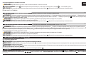
Sanus VML44A Användarmanual
- Kategori
- Platta väggfästen
- Typ
- Användarmanual

VML
44
A
Instruction Manual
Texto en español, página 26
Texte français page 30
Deutscher Text Seiten 34
Nederlandse tekst op pagina 38
Svensk text sida 42
46
中文文字说明请参见第 50 页
Русский текст: стр. 54
ES
FR
DE
NL
SV
JA
ZH
RU
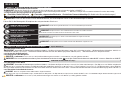
WE’RE HERE TO HELP
If you have any questions along the way,
our install experts are standing by to help.
Call us at:
+31 (0) 495 580 852
UK: 0800-056-2853
AUS: +61 (0) 7 3299 7000

2
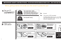
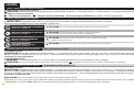
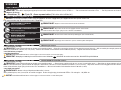
IMPORTANT SAFETY INSTRUCTIONS – PLEASE READ ENTIRE MANUAL PRIOR TO USE – SAVE THESE INSTRUCTIONS
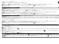
No
—
Perfect!
Yes
—
This mount is NOT compatible.
Visit MountFinder.Sanus.com or call +31 (0) 495 580 852
(UK: 0800-056-2853) (AUS: +61 (0) 7 3299 7000)
to fi nd a compatible mount.
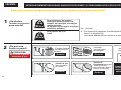
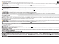
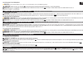
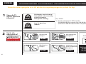
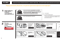
Before getting started, let’s make sure this mount is perfect for you!
1
2
What is your
wall made of?
Wood studs
(with drywall)?
Drywall
over wood studs?
36 kg
(80 lbs.)
23 kg
(50 lbs.)
Perfect!
Perfect!
Perfect!
Perfect!
Does your TV
(including accessories)
weigh MORE than ...
for wood stud, solid
concrete/concrete block
and drylined solid concrete/
concrete block (dot & dab)
for drywall (only)
Solid concrete or
concrete block?
Dryline
(Dot & Dab)
over solid concrete
or concrete block?
Unsure?
Call Customer Service:
+31 (0) 495 580 852
UK: 0800-056-2853
AUS: +61 (0) 7 3299 7000

3
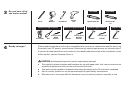
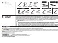
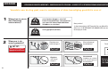
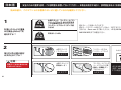
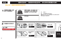
Please read through these instructions completely to be sure you’re comfortable with this easy install process.
Also check your TV owner’s manual to see if there are any special requirements for mounting your TV.
If you do not understand these instructions or have doubts about the safety of the installation, assembly or use
of this product, contact Customer Service.
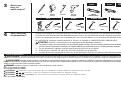
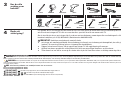
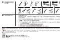
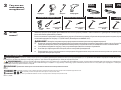
Do you have all of
the tools needed?
3
4
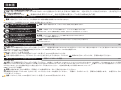
CAUTION: Avoid potential personal injuries and property damage!
● This product includes directions and hardware for use with wood studs, solid concrete and concrete block walls,
drywall and dryline over solid concrete and concrete block walls.
● The wall must be capable of supporting fi ve times the weight of the TV and mount combined.
● Do not use this product for any purpose not explicitly specifi ed by manufacturer.
● Manufacturer is not responsible for damage or injury caused by incorrect assembly or use.
Ready to begin?
Included Included
Wood Stud Applications Concrete Applications Drywall Applications Dryline Applications
3.2 mm (1/8 in.)
Wood
8 mm (5/16 in.)
Masonry
13 mm (1/2 in.) 8 mm (5/16 in.)
Masonry
Screwdriver
Tape
Measure
Stud Finder Hammer Hammer HammerAwl
Pencil
Drill Bit Drill Bit Drill Bit Drill Bit
Electric
Drill
Square Driver Bit Torx Driver Bit
T-30

4
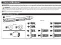
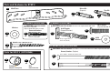
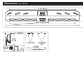
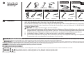
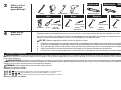
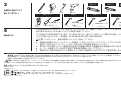
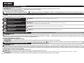
Parts and Hardware for STEP 1
M4 x 12mm
M8 x 16mm22mm
M8 x 20mm
M4 x 35mm
M8 x 35mm
M6 x 12mm
M6 x 35mm
M6 x 20mm
M6/M8
M4/M5
M5 x 12mm
M5 x 35mm
TV Bracket
01
x1
Parts and Hardware
WARNING: This product contains small items that could be a choking hazard if swallowed. Before starting assembly, verify all parts are included and
undamaged. If any parts are missing or damaged, do not return the damaged item to your dealer; contact Customer Service. Never use damaged parts!
NOTE: Not all hardware included will be used.
02
x2
03
x2
14
x2
04
x2
05
x2
06
x2
07
x2
08
x2
09
x2
13
x2
12
x2
11
x2
10
x2
TV Screws
Washers
Spacers
*
WARNING: This product contains a magnet. If an implanted medical device such as a pacemaker or implantable cardioverter defi brillator (ICD) is
in use, magnetic fi elds may a ect the operation of those devices, resulting in serious injury or death. If you have an implanted medical device, keep at least
13 cm (5 in.) between your device and the magnet. Please consult with your physician or medical professional prior to using this product.

5
#10 x 2 1/2 in.
10-24 x 1.25
Fischer UX8x50R
HILTI HRD-C 8X100 Screw/Anchor
Snap Toggler BA
3/16”-24 (10-24 )
For CONCRETE installations ONLY For DRYWALL installations ONLY
For DRYLINE (Dot & Dab) installations ONLY
Parts and Hardware for STEP 2
Parts for STEP 3 (OPTIONAL)
26
x2
27
x2
15
x1
20
x2
18
x2
19
x2
16
x1
21
x2
22
x2
23
x2
24
x2
25
x2
17
x1
Wall Plate
Concrete Anchors
Washers
Stando
*
(Magnetic Leveling Feet)
Disc
(Adhesive backed)
Wood Screws (Wall Plate Screws)
Driver Bit
(Square)
10-24 Toggler
(Drywall Anchor)
10-24 Screw
(Drywall Anchor Screw)
10-24
Washer
Screw / Anchor (Dryline)
Torx Bit
CAUTION: FOR STEP 2C ONLY:
Do not use in drywall,
dryline (dot & dab) walls or wood.
CAUTION: FOR STEP 2B ONLY: Do not use in dryline (dot & dab) walls.
CAUTION: FOR STEP 2D ONLY: Use ONLY in a concrete wall that has been drylined (dot & dab).
T-30

6
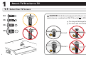
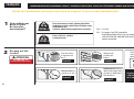
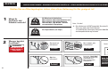
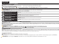
1
1. 1 Select Your TV Screws
CAUTION: Verify thread engagement with your screw/
washer/spacer combination AND TV bracket
01
in STEP 1.2.
•
Too long will damage the TV.
•
Too short will not hold the TV.
Too Short
Correct
Correct
Too Long
M4
M5
M6
M8
Attach TV Bracket to TV

7
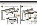
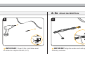
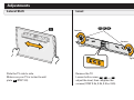
1. 2 Attach the TV Bracket
• Flat Back TV [spacers
04
not necessary]
• Rounded Back TV
• Extra Space Needed
[for cables or inset holes]
A B
B
Inset Holes
Cables
A
01
01
04
11 12 13
02
02
05
04
14
03
03
06 07 08 09 10
Top of TV
Top of TV

8
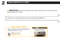
2
Attach Wall Plate to Wall
IMPORTANT: You must determine your wall construction to correctly secure
the wall plate to the wall.
Follow the corresponding step for your wall plate installation.
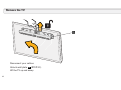
Recommended placement
Check it out at:
SANUS.com/1172
Get it right the fi rst time! HeightFinder
™
shows you where to drill.
WE’RE HERE TO HELP

9
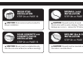
WOOD STUD
INSTALLATION
STEP
2A on PAGE 10
SOLID CONCRETE
AND
CONCRETE BLOCK
INSTALLATION
STEP
2C on PAGE 16
DRYWALL (only)
INSTALLATION
STEP
2B on PAGE 12
DRYLINE (Dot & Dab)
INSTALLATION
STEP
2D on PAGE 18
CAUTION: Stud centers must be located for
proper installation.
CAUTION: Mount must be installed directly
onto the concrete surface (no surface covering).
CAUTION: Drywall must be of sound
construction with no water damage. If water
damage ever occurs - remove the TV immediately.
CAUTION: Drywall must be mounted over solid
concrete or concrete block.

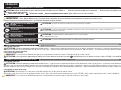
10
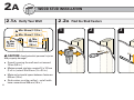
2A
CAUTION: Avoid potential personal injuries
and property damage!
● Drywall covering the wall must not exceed
16 mm (5/8 in.)
● Minimum wood stud size: nominal 51 x 102 mm
(2 x 4 in.) actual 38 x 89 mm (1½ x 3½ in.)
● Minimum horizontal space between fasteners:
406 mm (16 in.)
● Stud centers must be verified – not all walls
have conventional 406 mm (16 in.)
2 .1 A Verify Your Wall 2.2A Find the Stud Centers
WOOD STUD INSTALLATION
1 2 3
Max.
16 mm
(5/8 in.)
Min.
406 mm
(16 in.)
Min. 38 mm (1 1/2 in.)
Min. 89 mm (3 1/2 in.)

11
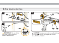
2.3A Attach the Wall Plate
4
5
6
CAUTION: Improper use could reduce the holding power
of screws
19
. DO NOT over-tighten the screws.
Go to STEP 3 on PAGE 20.
15
15
1916 18
IMPORTANT: 3.2 mm (1/8 in.)
pilot holes must be drilled to a
depth of 63 mm (2.5 in.).
63 mm (2.5 in.)
3.2 mm
(1/8 in.)

12
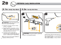
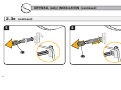
2B
CAUTION: Avoid potential personal
injuries and property damage!
● Drywall covering must be 13 mm
(1/2 in.) or greater
● Drywall must be mounted on studs,
406 mm (16 in.) apart, [
minimum wood
stud size: nominal 51 x 102 mm (2 x 4 in.)
actual 38 x 89 mm (1½ x 3½ in.)]
● Drywall must be sound with no
water damage. If water damage ever
occurs - remove the TV immediately.
●Minimum horizontal space between
fasteners: 305 mm (12 in.)
2.1B Verify Your Wall 2.2B Verify Drill Size
DRYWALL (only) INSTALLATION
Min.
13 mm (1/2 in.)
1 2
Drill 3.2 mm (1/8 in.) test holes to verify wall.
For drywall only, proceed with STEP 3.
For wood stud(s) - follow PAGE 10.
3.2 mm (1/8 in.)
Min.
305 mm
(12 in.)
CAUTION: Do not mount to patched
areas or on drywall seams.
15

13
3
IMPORTANT: 13 mm (1/2 in.) pilot holes must
be drilled to a depth of 25 mm (1 in.).
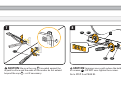
2.3B Attach the Wall Plate
13 mm
(1/2 in.)
25 mm (1 in.)
4
21
IMPORTANT: align the anchor so it will open
vertically as shown.

14
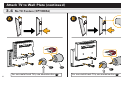
DRYWALL (only) INSTALLATION (continued)
65
21
21
2.3B (continued)

15
8
CAUTION: Improper use could reduce the holding power
of screws
22
. DO NOT over-tighten the screws.
Go to STEP 3 on PAGE 20.
7
P
21
CAUTION: Be sure the cap
P
is seated against the
drywall surface and the ends of the anchor do not extend
beyond the cap
P
- cut if necessary.
15
2322
22 23

16
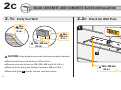
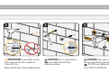
2C
2.1C Verify Your Wall
SOLID CONCRETE AND CONCRETE BLOCK INSTALLATION
CAUTION: Avoid potential personal injuries and property damage!
●Minimum solid concrete thickness: 203 mm (8 in.)
●Minimum concrete block size: 203 x 203 x 406 mm (8 x 8 x 16 in.)
●Minimum horizontal space between fasteners: 406 mm (16 in.)
●Mount wall plate
15
directly onto the concrete surface
2.2C Attach the Wall Plate
15
1
Min. 406 mm
(16 in.)
Min.
203 mm
(8 in.)
Min. 406 mm
(16 in.)
Min.
203 mm
(8 in.)

17
IMPORTANT: 8 mm (5/16 in.) pilot
holes must be drilled to a depth of
70 mm (2.75 in.).
Never drill into the mortar between blocks.
CAUTION: Be sure the anchors
20
are seated flush with the
concrete surface.
CAUTION: Improper use could
reduce the holding power of screws
19
. DO NOT over-tighten the screws.
Go to STEP 3 on PAGE 20.
8 mm
(5/16 in.)
70 mm (2.75 in.)
15
16 19
20
2 3 4
18

18
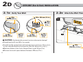
2D
2.1D Verify Your Wall
DRYLINE (Dot & Dab) INSTALLATION
CAUTION: Avoid potential personal injuries and property damage!
●Drywall must be 9.5 mm (3/8 in.) or greater
●Drywall must be mounted over solid concrete
[minimum thickness: 203 mm (8 in.)],
or over concrete block
[minimum block size: 203 x 203 x 406 mm (8 x 8 x 16 in.)]
●Maximum distance from front of drywall face to wall: 50 mm (2 in.)
●Minimum horizontal space between fasteners: 305 mm (12 in.)
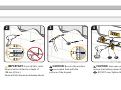
2.2D Attach the Wall Plate
15
1
Min.
305 mm (12 in.)
Min.
203 mm (8 in.)
Max.
50 mm
(2 in.)
Max.
50 mm
(2 in.)
Min.
203 mm
(8 in.)
Min. 406 mm (16 in.)
Min.
9.5 mm (3/8 in.)
Min.
9.5 mm (3/8 in.)

19
IMPORTANT: 8 mm (5/16 in.) pilot
holes must be drilled to a depth of
108 mm (4 ¼ in.).
Never drill into the mortar between blocks.
CAUTION: Be sure the anchors
25
are seated flush with the
surface of the drywall.
CAUTION: Improper use could
reduce the holding power of screws
24
. DO NOT over-tighten the screws.
8 mm (5/16 in.)
108 mm (4¼ in.)
15
17 24
25
2 3 4

20
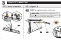
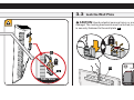
3
3.1 Unlock the Wall Plate 3.2 Hang Your TV
HEAVY! You may need assistance with this step.
Side View
15
1501
01
15
IMPORTANT: DO NOT lower TV straight down onto
wall plate
15
-- this will engage the lock. Safety latch must
be released for proper installation (See STEP 3.1).
Attach TV to Wall Plate
Sidan laddas...
Sidan laddas...
Sidan laddas...
Sidan laddas...
Sidan laddas...
Sidan laddas...
Sidan laddas...
Sidan laddas...
Sidan laddas...
Sidan laddas...
Sidan laddas...
Sidan laddas...
Sidan laddas...
Sidan laddas...
Sidan laddas...
Sidan laddas...
Sidan laddas...
Sidan laddas...
Sidan laddas...
Sidan laddas...
Sidan laddas...
Sidan laddas...
Sidan laddas...
Sidan laddas...
Sidan laddas...
Sidan laddas...
Sidan laddas...
Sidan laddas...
Sidan laddas...
Sidan laddas...
Sidan laddas...
Sidan laddas...
Sidan laddas...
Sidan laddas...
Sidan laddas...
Sidan laddas...
Sidan laddas...
Sidan laddas...
Sidan laddas...
Sidan laddas...
-
 1
1
-
 2
2
-
 3
3
-
 4
4
-
 5
5
-
 6
6
-
 7
7
-
 8
8
-
 9
9
-
 10
10
-
 11
11
-
 12
12
-
 13
13
-
 14
14
-
 15
15
-
 16
16
-
 17
17
-
 18
18
-
 19
19
-
 20
20
-
 21
21
-
 22
22
-
 23
23
-
 24
24
-
 25
25
-
 26
26
-
 27
27
-
 28
28
-
 29
29
-
 30
30
-
 31
31
-
 32
32
-
 33
33
-
 34
34
-
 35
35
-
 36
36
-
 37
37
-
 38
38
-
 39
39
-
 40
40
-
 41
41
-
 42
42
-
 43
43
-
 44
44
-
 45
45
-
 46
46
-
 47
47
-
 48
48
-
 49
49
-
 50
50
-
 51
51
-
 52
52
-
 53
53
-
 54
54
-
 55
55
-
 56
56
-
 57
57
-
 58
58
-
 59
59
-
 60
60


Sanus VML44A Användarmanual
- Kategori
- Platta väggfästen
- Typ
- Användarmanual
på andra språk
- español: Sanus VML44A Manual de usuario
- Deutsch: Sanus VML44A Benutzerhandbuch
- français: Sanus VML44A Manuel utilisateur
- 日本語: Sanus VML44A ユーザーマニュアル
- English: Sanus VML44A User manual
- русский: Sanus VML44A Руководство пользователя
- Nederlands: Sanus VML44A Handleiding
Relaterade papper
-
Sanus VML41 Installationsguide
-
-
Sanus Vuepoint F58c2 Användarmanual
-
-
-
-
-
Sanus VLF728 Användarmanual
-
-