Secura QSL22 Installationsguide
- Kategori
- Platta väggfästen
- Typ
- Installationsguide

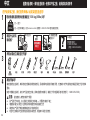
QSL
22
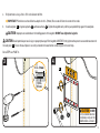
INSTRUCTION MANUAL
We’ll Make It Stress-Free
If you have any questions along the way, just give us a call.
1-800-359-5520 We’re ready to help!
Scan for easy install video
san.us/1141

2
Translations start on page 16
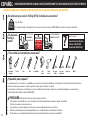
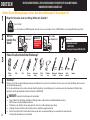
Wood Stud Install
Concrete Install
Tape
Measure
Pencil Level
Screw
driver
Electric
Drill
Socket
Wrench
Stud
Finder
Awl
Wood
Drill Bit
Masonry
Drill Bit
Hammer
3/8 in.
(10 mm)
1/2 in.
(13 mm)
7/32in.
(5.5 mm)
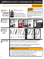
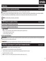
CAUTION: IMPORTANT SAFETY INSTRUCTIONS — PLEASE READ ENTIRE MANUAL PRIOR TO USE — SAVE THESE INSTRUCTIONS
Before getting started, let’s make sure this mount is perfect for you!
No? Perfect – you may continue.
Yes? This mount is NOT compatible.
Visit secura-av.com or call 1-800-359-5520
(UK: 0800 056 2853) to find a compatible mount.
Please read through these instructions completely to be sure you’re comfortable with this easy install process.
Also check your TV owner’s manual to see if there are any special requirements for mounting your TV.
If you do not understand these instructions or have doubts about the safety of the installation, assembly or use
of this product, contact Customer Service at
1-800-359-5520 (UK: 0800 056 2853).
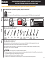
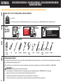
Do you have
all the tools
needed?
1
2
3
4
What is your
wall made of?
Ready to begin?
Solid concrete or
concrete block?
Perfect!
Drywall with
wood studs?
Perfect!
CAUTION:
DO NOT
install into
drywall alone
Unsure?
Call Customer Service:
1-800-359-5520
(UK: 0800 056 2853)
?
35 lbs.
(15.8 kg)
Does your TV
(including accessories)
weigh MORE than
35 lbs. (15.8 kg)?
CAUTION:
DO NOT exceed the maximum weight
indicated. This mounting system is intended for use only
with the maximum weights indicated. Use with products
heavier than the maximum weights indicated may result
in collapse of the mount and its accessories, causing
possible injury.
CAUTION: Avoid potential personal injury or property damage!
● This product is designed for use in wood stud, solid concrete, and concrete block walls - DO NOT install into drywall alone
● The wall must be capable of supporting five times the weight of the TV and mount combined
● Do not use this product for any purpose not explicitly specified by manufacturer
● Manufacturer is not responsible for damage or injury caused by incorrect assembly or use

3
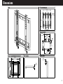
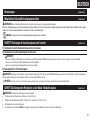
8.86in
[225mm]
7.99in
[203mm]
.33 in
[8.5mm]
2.95in
[75mm]
TV INTERFACE
7.64in
[194mm]
10.04in
[255mm]
4.96in
[126mm]
8.81in
[224mm]
9.25in
[235mm]
4.92in
[125mm]
.79in
[20mm]
.35in
[9mm]
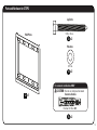
WALL PLATE
8.66in
[220mm]
10.04in
[255mm]
FULLY ASSEMBLED MOUNT
1.06in
[27mm]
TOP VIEW
.47in
[12mm]
SIDE VIEW
3-D
Dimensions

4
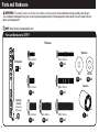
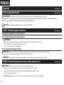
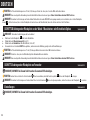
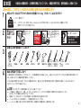
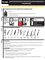
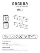
Parts and Hardware
WARNING: This product contains small items that could be a choking hazard if swallowed. Before starting assembly, verify all parts
are included and undamaged. If any parts are missing or damaged, do not return the damaged item to your dealer; contact Customer Service.
Never use damaged parts!
NOTE: Not all hardware included will be used.
Parts and Hardware for STEP 1
M4 M6/M8
5/16 x 2¾ in.
5/16 in.
Fischer UX 10 x 60R
Concrete Anchors
For concrete installations ONLY
CAUTION: Do not use in drywall or wood
M6 x 12mm M6 x 35mm
M8 x 16mm M8 x 35mm
M8 x 20mm
M4 x 12mm M4 x 35mm
22mm
TV Brackets
TV Screws
Washers
Spacers
02 x4 06 x4
03 x4
05 x4
07 x4
04 x4 08 x4
09 x4 10 x4
11 x4
01 x2
Locking
Screw
(Attached to
TV Brackets)
S

5
M4 M6/M8
5/16 x 2¾ in.
5/16 in.
Fischer UX 10 x 60R
Concrete Anchors
For concrete installations ONLY
CAUTION: Do not use in drywall or wood
M6 x 12mm M6 x 35mm
M8 x 16mm M8 x 35mm
M8 x 20mm
M4 x 12mm M4 x 35mm
Parts and Hardware for STEP 2
Lag Bolts
Washers
Wall Plate
13 x2
14 x2
15 x2
12 x1

6
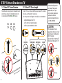
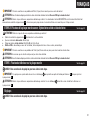
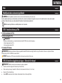
STEP 1 Attach Brackets to TV
FLAT BACK ROUND BACK CABLESINSET HOLES
1-1 Select TV
Screw Diameter
1-2 Select TV
Screw Length
Hand thread screws into the threaded inserts
on the back of your TV to determine which
screw diameter (M4, M6, or M8) to use.
a
b
If your TV has a flat back AND you want your TV closer to
the wall, use the shorter screws (a).
Use the spacers and longer screws (b) to accommodate:
● Round/irregular back TVs
● TVs with inset mounting holes
● Extra space needed for cables
M6M4 M8
Too Short
Too Long
CAUTION:
Verify adequate thread
engagement with your screw/
washer/spacer combination
AND TV bracket.
- Too short will not hold the TV.
- Too long will damage the TV.
Correct
Standard configurations
are shown. For special
applications, or if you
are uncertain about your
hardware selection,
contact Customer Service
at 1-800-359-5520.

7
1-3 Attach TV Brackets
a
Flat Back
b
Round Back / Extra Space
Ensure that your brackets are level and centered on the back of the TV.
Install using the TV screw/washer/spacer configuration you selected for your TV.
CAUTION: Avoid potential personal injuries and property damage! DO NOT use power tools for this step. Tighten the screws only enough
to secure the TV bracket to the TV. DO NOT overtighten the screws.
IMPORTANT: Ensure TV brackets are securely fastened before moving on to the next step.
02 03
06
04
07
05
08
09 10
09 10
11
01

8
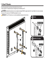
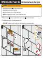
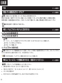
1. Locate your studs. Verify and mark the center of the stud by finding the stud edges using an awl, a thin nail, or an edge to edge stud finder.
2. Position the wall plate
12
at your desired height and line up the holes with your stud center line and level the wall plate
12
and mark the holes.
2
1
Max. 5/8 in.
(16 mm)
STEP 2A Attach Wall Plate to Wall
Wood Stud Option
CAUTION: Avoid potential personal injury or property damage!
● Drywall covering the wall, must not exceed 5/8 in. (16 mm)
● Minimum wood stud size: common 2 x 4 in. (51 x 102 mm) nominal 1½ x 3½ in. (38 x 89 mm)
● Stud center must be verified
● DO NOT use the slotted holes for installation, only use the middle holes as shown
CAUTION: DO NOT
use the slotted holes for
installation, only use the
middle holes as shown
12

9
4
3
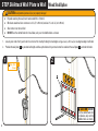
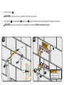
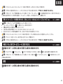
3. Drill pilot holes using a 7/32 in. (5.5 mm) diameter drill bit.
IMPORTANT: Pilot holes must be drilled to a depth of 2¾ in. (70 mm). Be sure to drill into the center of the studs.
4. Install wall plate
12
using two lag bolts
13
and two washers
14
. Tighten the lag bolts only until they are pulled firmly against the wall plate.
CAUTION: Improper use could reduce the holding power of the lag bolt. DO NOT over-tighten the lag bolts.
CAUTION: Avoid potential personal injury or property damage! Both lag bolts MUST BE firmly tightened to prevent unwanted movement of
the wall plate
12
.
Ensure the wall plate is securely fastened to the wall before continuing on to the next step.
Go to STEP 3 on PAGE 12.
CAUTION: DO NOT
use the slotted holes for
installation, only use the
middle holes as shown
7/32 in.
(5.5 mm)
2¾
in. (70 mm)
12
14
13

10
● Mount the wall plate assembly
12
directly onto the concrete surface
● Minimum solid concrete thickness: 8 in. (203 mm)
● Minimum concrete block size: 8 x 8 x 16 in. (203 x 203 x 406 mm
● DO NOT use the slotted holes for installation, only use the middle holes as shown
1. Position the wall plate
12
on the wall at your desired height. Level the wall plate
12
and mark the hole locations.
2. Drill two pilot holes using a 3/8 in. (10 mm) diameter masonry drill bit.
IMPORTANT: Pilot holes must be drilled to a depth of 3 in. (75 mm). Never drill into the mortar between blocks.
2
1
002862.eps
STEP 2B Attach Wall Plate to Wall
Solid Concrete or Concrete Block Option
CAUTION: Avoid potential personal injury or property damage!
CAUTION: DO NOT
use the slotted holes for
installation, only use the
middle holes as shown
3/8 in.
(10 mm)
3 in. (75 mm)
12

11
43
3. Insert two anchors
15
.
CAUTION: Be sure the anchors are seated flush with the concrete surface.
4. Install wall plate
12
using two lag bolts
13
and washers
14
. Tighten the lag bolts only until they are pulled firmly against the wall plate.
CAUTION: Improper use could reduce the holding power of the lag bolt. DO NOT over-tighten the lag bolts.
CAUTION: DO NOT
use the slotted holes for
installation, only use the
middle holes as shown
12
14
13
15

12
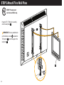
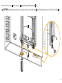
STEP 3 Attach TV to Wall Plate
HEAVY! You may need
assistance with this step.
Hang the TV / TV Bracket assembly
onto the wall plate
12
.
IMPORTANT: You may need to back
out the locking screws
S
to allow the
TV brackets
01
to rest flat against the
wall plate
12
.
12
01
S

13
Secure the TV brackets
01
to the wall plate
12
by tightening the locking screws
S
.
CAUTION: Avoid potential personal injury or property damage! Locking screws
S
must be tightened to secure the TV to the wall plate
12
.
12
01
12
01
S
S

14
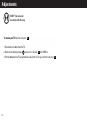
Adjustments
HEAVY! You may need
assistance with this step.
To remove your TV from the wall plate
12
,
1. Disconnect all cables from the TV.
2. Back out the locking screws
S
to clear the wall plate
12
. See PAGE 13.
3. Pull the bottom of the TV away from the wall and lift the TV up and o the wall plate
12
.

15

16
¿Su televisor pesa más de 15,8 kg (35 lb) incluidos los accesorios?
No: ¡Perfecto!
Sí: Esta montura NO es compatible. Visite secura-av.com o llame al número 1-800-359-5520 para encontrar una montura compatible.
ESPAÑOL
INSTRUCCIONES IMPORTANTES DE SEGURIDAD: GUARDE ESTAS INSTRUCCIONES Y LEA TODO EL MANUAL ANTES DE UTILIZAR ESTE PRODUCTO.
¿Preparado para empezar?
Lea atentamente estas instrucciones en su totalidad para asegurarse de que está familiarizado con el sencillo proceso de instalación. Consulte igualmente el
manual de su televisor para conocer si existen requisitos especiales para el montaje de su aparato.
Si no entiende las instrucciones o si tiene dudas acerca de la seguridad de la instalación, el montaje o el uso del producto, póngase en contacto con el
Servicio de Atención al Cliente al número 1-800-359-5520.
PRECAUCIÓN: ¡Evite posibles lesiones personales y daños materiales!
● Este producto se ha diseñado para su uso en montantes de madera, hormigón macizo y paredes de bloques de hormigón:
NO lo instale en paredes únicamente de yeso
● La pared debe ser capaz de soportar hasta cinco veces el peso combinado del televisor y la montura
● No utilice este producto para ningún otro propósito que no sea el explícitamente especificado por el fabricante
● El fabricante no se responsabiliza de ningún daño o lesión resultante del montaje incorrecto o el uso indebido
¡Antes de empezar, asegúrese de que este es el soporte adecuado para usted!
1
2
3
4
¿De qué está
hecha la
pared?
¿Tiene todas las herramientas necesarias?
15,8 kg
(35 lbs)
Localizador de
montantes
Punzón Lápiz Nivel Destornillador Cinta
métrica
Taladro
eléctrico
Broca para
madera
Broca para
mampostería
Llave de vaso Martillo
13 mm
(1/2 pulg.)
5 mm
(7/32 pulg.)
10 mm
(3/8 pulg.)
¿Hormigón macizo o
bloque de hormigón?
¿Paneles de yeso
con montantes
de madera?
¡Perfecto!
¡Perfecto!
PRECAUCIÓN:
NO instalar en
panel de yeso
solo
¿No está seguro?
Llame al Servicio de Atención
al Cliente: 1-800-359-5520
(Reino Unido: 0800-056-2853)
?

17
ESPAÑOL
Dimensiones Consulte la página 3
Piezas y elementos de sujeción suministrados Consulte la página 4
ADVERTENCIA: Este producto contiene piezas pequeñas que, en caso de ser tragadas, podrían causar asfixia.
Antes de comenzar a montar la unidad, verifique que dispone de todas las piezas y que se encuentran en buen estado. Si no dispone de todas las piezas o alguna está dañada,
no devuelva el elemento defectuoso al distribuidor. Póngase en contacto con el servicio de atención al cliente. ¡Nunca utilice piezas en mal estado!
NOTA: No se utilizarán todos los elementos de sujeción incluidos.
PASO 1 Conectar los soportes al televisor Consulte la página 6
1.1 Seleccione el diámetro de los tornillos del televisor
1.2 Seleccione la longitud de los tornillos del televisor
PRECAUCIÓN:
Verifique el enrosque adecuado de la combinación tornillo/arandela/espaciador Y soporte del televisor.
- Si es demasiado corto, no sujetará el televisor.
- Si es demasiado largo, dañará el televisor.
1.3 Fije los soportes del televisor
PRECAUCIÓN: Evite posibles lesiones personales y daños materiales. NO use herramientas eléctricas para este paso. Apriete los tornillos con la fuerza adecuada para fijar
el soporte del televisor al televisor. NO los apriete demasiado.
IMPORTANTE: Asegúrese de que los soportes del televisor estén firmemente sujetos antes de pasar al paso siguiente.
PASO 2A Fijar la placa de pared a la pared - Opción de montante de madera Consulte la página 8
PRECAUCIÓN: ¡Evite posibles lesiones personales o daños materiales!
● Los paneles de yeso sobre la pared no deben ser mayores de 16 mm (5/8 pulg.)
● Tamaño mínimo de los montantes de madera: común 51 x 102 mm (2 x 4 pulg.) nominal 38 x 89 mm (1½ x 3½ pulg.)
● El centro del montante debe ser verificado
● NO utilice las ranuras para la instalación, utilice únicamente los orificios centrales como se muestra.

18
ESPAÑOL
IMPORTANTE: Los orificios guía deben taladrarse hasta una profundidad de 70 mm (2¾ pulg.). Asegúrese de taladrar en el centro del montante.
PRECAUCIÓN: El uso incorrecto podría reducir la capacidad de sujeción del perno tirafondo. NO apriete excesivamente los pernos tirafondo.
PRECAUCIÓN: ¡Evite posibles lesiones personales o daños materiales! Los dos pernos tirafondo DEBEN ESTAR fijados con firmeza para evitar movimientos no deseados
de la placa de pared
12
. Asegúrese de que la placa de pared esté bien fijada a la pared antes de continuar con el paso siguiente.
PASO 2B Fijar la placa de pared a la pared - Opción de hormigón macizo o bloques de hormigón Consulte la página 10
PRECAUCIÓN: Evite posibles lesiones personales o daños materiales.
● Monte el conjunto de placa de pared
12
directamente sobre la superficie de hormigón
● Grosor mínimo del hormigón macizo: 203 mm (8 pulg.)
● Tamaño mínimo del bloque de hormigón: 203 x
203 x 406 mm (8 x 8 x 16 pulg.)
● NO utilice las ranuras para la instalación, utilice únicamente los orificios centrales como se muestra
IMPORTANTE: Los orificios guía deben taladrarse hasta una profundidad de 75 mm (3 pulg.). Nunca taladre sobre el cemento entre los bloques.
PRECAUCIÓN: Asegúrese de que los anclajes estén asentados al mismo nivel que la superficie de hormigón.
PRECAUCIÓN: El uso incorrecto podría reducir la capacidad de sujeción del perno tirafondo. NO apriete excesivamente los pernos tirafondo.
PASO 3 Fijar el televisor a la placa de pared Consulte la página 12
¡PRODUCTO PESADO! Podría necesitar ayuda para realizar esta operación.
IMPORTANTE: Es posible que necesite retirar los tornillos de bloqueo
S
para que los soportes del televisor
01
queden planos contra la placa de la pared
12
.
PRECAUCIÓN: Evite posibles lesiones personales o daños materiales. Los tornillos de bloqueo
S
deben estar ajustados para fijar el televisor a la placa de pared
12
.
Ajustes Consulte la página 14
¡PRODUCTO PESADO! Podría necesitar ayuda para realizar esta operación.

19
INFORMATIONS IMPORTANTES CONCERNANT LA SÉCURITÉ – CONSERVEZ CES INSTRUCTIONS –
VEUILLEZ LIRE ATTENTIVEMENT LE MANUEL AVANT D’UTILISER CE PRODUIT
Votre téléviseur pèse-t-il plus de 15,8 kg (35lb), y compris les accessoires ?
Non
—
Parfait!
OUI
—
Ce support n'est PAS compatible. Rendez-vous sur secura-av.com ou appelez le 1-800-359-5520 pour trouver un support compatible.
Vous êtes prêt à commencer?
Veuillez lire intégralement ces instructions afin que vous soyez à l'aise avec ce processus d'installation facile. Veuillez également consulter le manuel
du propriétaire de votre téléviseur pour savoir si son installation présente des exigences particulières.
Si vous ne comprenez pas toutes ces instructions ou si vous avez des doutes sur la sécurité de l'installation, du montage ou de l’utilisation de ce produit,
veuillez contacter le service à la clientèle au 1-800-359-5520.
ATTENTION : Évitez les risques de blessures corporelles ou de dommages matériels!
● Ce produit est conçu pour une utilisation sur des montants en bois, des murs en béton solide et en bloc de béton - Ne l'installez PAS seul sur une cloison sèche.
● Le mur doit pouvoir supporter cinq fois le poids total du téléviseur et du support.
● N'utilisez pas ce produit à d’autres fins que celles spécifiées par le fabricant.
● Le fabricant n’est pas responsable des blessures ou des dommages causés par une mauvaise utilisation ou un montage incorrect.
Avant de commencer, assurons-nous que ce support vous convient parfaitement!
1
2
3
4
De quoi est
fait le mur?
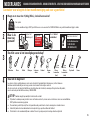
Avez-vous tous les outils requis?
15,8 kg
(35 lbs)
Détecteur
de montants
Alêne Crayon Niveau Tournevis Ruban
à mesurer
Perceuse
électrique
Foret à bois Foret de
maçonnerie
Clé à
douilles
Marteau
13 mm
(1/2 po)
5 mm
(7/32 po)
10 mm
(3/8 po)
Béton solide ou
bloc de béton ?
Cloison sèche à
montants en bois ?
Parfait!
Parfait!
ATTENTION :
Ne l'installez PAS
seul sur une cloison
sèche
Vous avez des doutes?
Contactez le service à la clientèle :
1-800-359-5520
(RU : 0800-056-2853)
?
FRANÇAIS

20
Dimensions Voir à la page 3
Pièces et quincaillerie fournies Voir à la page 4
ÉTAPE1 Fixation des supports au téléviseur Voir à la page 6
AVERTISSEMENT: Ce produit contient de petites pièces qui peuvent représenter un risque d’étouffement si elles sont avalées.
Avant de commencer l’assemblage, assurez-vous qu'il ne manque aucune pièce et qu’elles ne sont pas endommagées. Si une pièce est manquante ou endommagée,
contactez le service à la clientèle et non le détaillant. N’utilisez jamais de pièces endommagées!
REMARQUE: Les pièces fournies ne doivent pas nécessairement être toutes utilisées.
1.1 Sélectionnez le diamètre des vis pour le téléviseur
1.2 Sélectionnez la longueur des vis pour le téléviseur
ATTENTION :
Assurez-vous que la longueur du filetage de la combinaison vis/rondelle/entretoise ET patte de fixation est correcte.
- Si elle est insuffisante, il sera impossible de maintenir le téléviseur.
- Si elle est excessive, le téléviseur sera endommagé.
1.3 Fixez les pattes de fixation pour téléviseur
ATTENTION: Évitez les risques de blessures corporelles ou de dommages matériels! N'utilisez pas d'outils électriques pour cette étape.
Serrez les vis juste assez pour fixer la patte de fixation au téléviseur. Ne serrez PAS trop les vis.
IMPORTANT : Assurez-vous que les pattes de fixation pour téléviseur sont correctement fixées avant de passer à l'étape suivante.
ATTENTION: Évitez les risques de blessures corporelles ou de dommages matériels!
● L’épaisseur du revêtement de cloison sèche qui recouvre le mur ne doit pas excéder 16mm (5/8po)
● Taille minimum des montants en bois: habituelle 51 x 102 mm (2 x 4 po), nominale 38 x 89 mm (1½ x 3½ po)
● Le centre des montants doit être vérifié
● N'utilisez PAS les trous oblongs au cours de l'installation ; utilisez uniquement les trous situés au centre, comme indiqué.
ÉTAPE 2A Fixation de la plaque murale au mur - Option montants en bois Voir à la page 8
FRANÇAIS
Sidan laddas...
Sidan laddas...
Sidan laddas...
Sidan laddas...
Sidan laddas...
Sidan laddas...
Sidan laddas...
Sidan laddas...
Sidan laddas...
Sidan laddas...
Sidan laddas...
Sidan laddas...
Sidan laddas...
Sidan laddas...
Sidan laddas...
Sidan laddas...
Sidan laddas...
Sidan laddas...
Sidan laddas...
Sidan laddas...
-
 1
1
-
 2
2
-
 3
3
-
 4
4
-
 5
5
-
 6
6
-
 7
7
-
 8
8
-
 9
9
-
 10
10
-
 11
11
-
 12
12
-
 13
13
-
 14
14
-
 15
15
-
 16
16
-
 17
17
-
 18
18
-
 19
19
-
 20
20
-
 21
21
-
 22
22
-
 23
23
-
 24
24
-
 25
25
-
 26
26
-
 27
27
-
 28
28
-
 29
29
-
 30
30
-
 31
31
-
 32
32
-
 33
33
-
 34
34
-
 35
35
-
 36
36
-
 37
37
-
 38
38
-
 39
39
-
 40
40


Secura QSL22 Installationsguide
- Kategori
- Platta väggfästen
- Typ
- Installationsguide
på andra språk
- español: Secura QSL22 Guía de instalación
- Deutsch: Secura QSL22 Installationsanleitung
- français: Secura QSL22 Guide d'installation
- 日本語: Secura QSL22 インストールガイド
- English: Secura QSL22 Installation guide
- русский: Secura QSL22 Инструкция по установке
- Nederlands: Secura QSL22 Installatie gids
Relaterade papper
-
 Secura QMT25 Installationsguide
-
 Secura QLT35 Installationsguide
-
 Secura QLL23 Installationsguide
-
 Secura QSF207 Installationsguide
-
 Secura QSF210 Installationsguide
-
 Secura QML22 Installationsguide
-
 Secura QLF314 Installationsguide
-
Secura QMF110 Installationsguide
-
 Secura QSL12 Installationsguide
-
 Secura QML12 Installationsguide


