Secura QSF207 Installationsguide
- Kategori
- Platt skärmfästen
- Typ
- Installationsguide

QSF
207
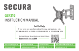
INSTRUCTION MANUAL
Let Us Help
If you have any questions along the way, just give us a call.
US: 800-359-5520 • EMEA: +31 (0) 495 580 852 • UK: 0800 056 2853
For HeightFinder, MountFinder and Install Videos,
Scan or visit san.us/2904
Texto en español, página 24
Deutscher Text Seiten 32
Svensk text sida 40
Русский текст: стр. 52
Texte français page 28
Nederlandse tekst op pagina 36
日本語は 44 ページ
中文文字说明请参见第 48 页

2
11.3 kg
(25 lbs.)
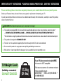
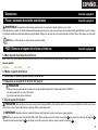
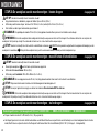
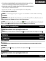
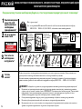
IMPORTANT SAFETY INSTRUCTIONS – PLEASE READ MANUAL PRIOR TO USE – SAVE THESE INSTRUCTIONS
Please read through these instructions completely to be sure you’re comfortable with this easy install process.
Check your TV owner’s manual to see if there are any special requirements for mounting your TV.
If you do not understand these instructions or have doubts about the safety of the installation, assembly or use of this product,
contact Customer Service.
CAUTION: Avoid potential personal injuries and property damage!
● This product is designed ONLY to be installed into wood studs, solid concrete or concrete block, and steel studs*,
— DO NOT INSTALL INTO DRYWALL ALONE — DRYWALL ALONE WILL NOT HOLD THE WEIGHT OF YOUR TV.
*For information on using this product with steel stud walls contact Customer Service and ask about the steel stud mounting kit.
● This product is designed for INDOOR USE ONLY.
● The wall must be capable of supporting five times the weight of the TV and mount combined.
● Do not use this product for any purpose not explicitly specified by manufacturer.
● Manufacturer is not responsible for damage or injury caused by incorrect assembly or use.
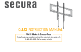
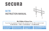
TV Weight Limit
(including accessories)
DO NOT EXCEED
If your TV (plus accessories) weighs MORE,
this mount is NOT compatible.
Visit secura-av.com or call customer service to
find a compatible mount.
800-359-5520 • EMEA: +31 (0) 495 580 852 •
UK: 0800 056 2853

3
Call Customer Service
800-359-5520 • EMEA: +31 (0) 495 580 852 •
UK: 0800 056 2853
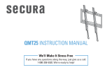
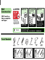
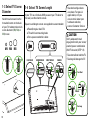
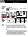
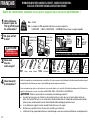
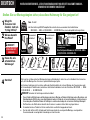
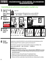
Tools Needed
Wall
Construction
ONLY install on
these acceptable
wall types.
steel studs
Drywall alone
will
NOT hold the
weight of your TV
Unsure
wood studs Solid concrete
or concrete
block
ACCEPTABLE ACCEPTABLE
Steel stud kit #SSMK1 is
required [NOT INCLUDED]
Call Customer Service
Wood Stud Install
Steel Stud Install
Concrete Install
Awl Awl
Pencil Level Tape
Stud
Finder
Stud
Finder
ScrewdriverTape
Measure
1/8 in.
(3 mm)
Wood
1/2 in.
(13 mm)
Steel
Drill Bit Drill Bit
Electric
Drill
Hammer
7/16 in.
(12 mm)
Socket
Wrench
Drill Bit
3/8 in.
(10 mm)
Concrete
CAUTION:
DO NOT
install in
drywall
alone
IMPORTANT SAFETY INSTRUCTIONS – PLEASE READ MANUAL PRIOR TO USE – SAVE THESE INSTRUCTIONS
ACCEPTABLE

4
7.87
200.0
3.94
100.0
7.87
200.0
0.35
8.8
7.19
182.6
2.56
65.0
5.22
132.5
1.04
26.3
0.28
7.0
0.28
7.0
13°
8.87
225.2
8.80
223.6
3.29
83.6
4.27
108.6
OFFSET
16°
4°
SIMULATED
32" TV
7.56
192.1
W/EXTENSIONS
30°
30°
7.29
185.1
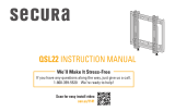
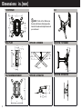
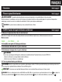
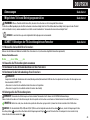
TV INTERFACE
WALL PLATE
FULLY ASSEMBLED MOUNT
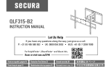
TOP VIEW - EXTENDED
TOP VIEW - RETRACTED
SIDE VIEW - TILT RANGE
SIDE VIEW - RETRACTED
3-D
Dimensions in. [mm]
NOTE: TV shifts 4.27 in. (108.6 mm) to
the right or left when in the home position.
Consider this when selecting the location of
your wall mount.

5
M4 x 8mm
22 mm
8-32 x 3/8 in.
8-32
1/4 in.
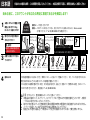
WELCOME! THANKS FOR CHOOSING SANUS.
THIS IS GOING TO BE EASY! LET’S GET STARTED.
STEP 2
STEP 3
STEP 1
Attach TV brackets on back of TV.
1/4 x 2½ in.
M4 x 12mm
M6 x 12mm M6 x 35mm
M4 x 35mm
M8 x 20mm
M8 x 35mm
TV Bracket
TV Bracket Extenders
TV Bracket
Screws
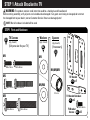
STEP 1 Attach Bracket to TV
05 x4
04 x1
06 x8
WARNING: This product contains small items that could be a choking hazard if swallowed.
Before starting assembly, verify all parts are included and undamaged. If any parts are missing or damaged, do not return
the damaged item to your dealer; contact Customer Service. Never use damaged parts!
NOTE: Not all hardware included will be used.
STEP 1 Parts and Hardware
TV Screws
(qty. 4 each)
[Only one size fits your TV]
M4
M4
M6/M8
M4/M6/M8
M6
M8
Washers
(qty. 4 each)
Spacers
(qty. 4 each)
[If necessary]
03
02
01

6
M4 x 8mm
22 mm
8-32 x 3/8 in.
8-32
1/4 in.
1/4 x 2½ in.
Fischer UX10 x 60R
Concrete Anchors
For concrete installations ONLY
CAUTION
: Do not use in drywall or wood
M4 x 12mm
M6 x 12mm M6 x 35mm
M4 x 35mm
M8 x 20mm
M8 x 35mm
Wall Plate/ Arm Assembly
Lag Bolt
08 x2
07 x1
09 x2
10 x2
Lag Screw Washer
STEP 2 Parts and Hardware

7
1/4-20 Snap Toggle BB
Fischer UX10 x 60R
Concrete Anchors
For concrete installations ONLY
CAUTION: Do not use in drywall or wood
1/4-20 x 1.75
1/4 in.
1/4 in.
1/4 x 2½ in.
M4 x 8mm
22 mm
8-32 x 3/8 in.
8-32
1/4 in.
1/4 x 2½ in.
Fischer UX10 x 60R
Concrete Anchors
For concrete installations ONLY
CAUTION
: Do not use in drywall or wood
M4 x 12mm
M6 x 12mm M6 x 35mm
M4 x 35mm
M8 x 20mm
M8 x 35mm
S1 x2
S3 x2
S2 x2
Securement Screw
11 x1
Securement Washer
12 x1
STEP 3 Hardware
Hardware for STEP 2C
Steel Stud Installation
[Steel Stud Anchor Kit #SSMK1 is NOT INCLUDED]
Contact Customer Service:
800-359-5520 • EMEA: +31 (0) 495 580 852 • UK: 0 800 056
2853
to inquire about these additional pieces.
Anchor
Washer
Screw

8
M4/M5 WASHER
Qty 4
M6/M8 WASHER
Qty 4
SPACER
Qty 4
M4 x 12mm SCREW
Qty 4
M8 x 20mm SCREW
Qty 4
M4 x 35mm SCREW
Qty 4
M5 x 12mm SCREW
Qty 4
M5 x 35mm SCREW
Qty 4
M8 x 35mm SCREW
Qty 4
M6 x 12mm SCREW
Qty 4
M6 x 35mm SCREW
Qty 4
M4/M5 M6
M4 x 12mm
M6 x 12mm
M4 x 35mm
M6 x 35mm
M6 x 20mm
M5 x 12mm
M6 x 12mm
M5 x 35mm
M4 x 8mm
M6 x 14mm
1/4 x 2 ½ in.
cm
inches
STEP 1 Attach TV Bracket to TV
These smaller hole patterns only use TV bracket
04
.
Do not use the four TV bracket extenders
05
and eight screws
06
.
Dimensions in cm.
7.5 x 7.5
10.0 x 10.0
10.0
10.0
7.5
1-1 Measure Your TV Hole Pattern 1-2 Assemble Your TV Bracket
Determine which TV bracket configuration to use, A, B, or C
based on your TV hole pattern measurements.
cm
inches
06
inch dimensions are approximate
75 mm = 7.5 cm ≈ 3 in.
100 mm = 10 cm ≈ 4 in.
200 mm = 20 cm ≈ 7⅞ in.
Measure the width and height of your TV hole
pattern in cm.
Record your measurements:
Width ________cm x Height ________cm
A
7.5
04
Record your measurements:
Width ________cm x Height ________cm
05

9
Assemble TV bracket extenders
05
onto TV bracket
04
.
Secure using eight screws
06
in the corner holes shown.
B C
04
04
Dimensions in cm.
Dimensions in cm.
20.0 x 20.0
20.0
20.0
06
Assemble TV bracket extenders
05
onto TV bracket
04
.
Secure using eight screws
06
in the corner holes shown.
20.0 x 10.0
20.0
10.0
06
05
05
05
05
05
05
05
05

10
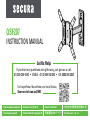
1-3 Select TV Screw
Diameter
1-4 Select TV Screw Length
Too Short
Too Long
CAUTION:
Verify adequate thread
engagement with your screw/
washer/spacer combination
AND TV bracket (STEP 1.5).
- Too short will not hold the TV.
- Too long will damage the TV.
Correct
Standard configurations
are shown. For special
applications, or if you
are uncertain about your
hardware selection,
contact Customer Service
M6 M8
FLAT BACK ROUND BACK CABLESINSET HOLES
M4
If your TV has a flat back AND you want your TV closer to
the wall, use the shorter screws.
Spacers and longer screws are supplied to accommodate:
● Round/irregular back TVs
● TVs with inset mounting holes
● Extra space needed for cables
Hand thread screws into the
threaded inserts on the back
of your TV to determine which
screw diameter (M4, M6, or
M8) to use.

11
Flat Back
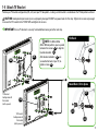
1-5 Attach TV Bracket
TV Bracket
Configuration A
Illustrated
(with spacers)
TV Bracket
Configuration B
Illustrated
(with spacers)
NOTE: For 20.0 x 20.0 or
20.0 x 10.0 hole patterns, you may need
to loosen the screws
06
to align the
bracket extenders
05
.
After bracket extenders
05
are
secured to the back of your TV, re-
tighten screws
06
.
Round Back / Extra Space
03
02
01
02
01
04
05
04
Position your TV bracket configuration (A, B, or C)
over your TV hole pattern - making sure the bracket is centered over the TV hole pattern and level.
CAUTION: Avoid potential personal injuries and property damage! DO NOT use power tools for this step. Tighten the screws only enough
to secure the TV bracket to the TV. DO NOT overtighten the screws.
IMPORTANT: Ensure TV bracket is securely fastened before moving on to the next step.

12
2 3
≤ 5/8 in.
(16 mm)
1
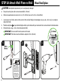
NOTE: TV shifts
4.27 in. (108.6 mm)
to the right or left
when in the home
position. Consider
this when select-
ing the location of
your wall mount.
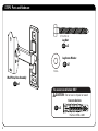
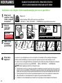
STEP 2A Attach Wall Plate to Wall
Wood Stud Option
1/8 in.
(3 mm)
2½
in. (64 mm)
CAUTION: Avoid potential personal injuries and property damage!
● Drywall covering the wall must not exceed 5/8 in. (16 mm)
● Minimum wood stud size: nominal 2 x 4 in. (51 x 102 mm) actual 1½ x 3½ in. (38 x 89 mm)
1. Locate your stud. Verify and mark the center of the stud by finding the stud edges using an awl, a thin nail, or an edge to
edge stud finder.
2. Position wall plate
07
at your desired height and line up the holes with your stud center line. Level and mark the hole locations.
3. Drill pilot holes using a 1/8 in. (3 mm) diameter drill bit.
.
IMPORTANT: Be sure to drill into the center of the stud.
IMPORTANT: Pilot holes must be drilled to a depth of 2 ½ in. (64 mm).
07

13
09
08
08
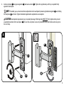
4
4. Install wall plate
07
using two lag bolts
08
and two washers
09
. Tighten the lag bolts only until they are pulled firmly
against the wall plate.
NOTE: If needed, you can make small level adjustments to the wall plate by loosening the bottom lag bolt
08
and shifting
the wall plate
07
until level. Tighten the bottom lag bolt when adjustments are complete.
CAUTION: Avoid potential personal injury or property damage! Both lag bolts MUST BE firmly tightened to prevent
unwanted movement of the wall plate
07
.
Ensure the wall plate is securely fastened to the wall before continuing on to
the next step.
07
07

14
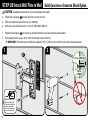
CAUTION: Avoid potential personal injuries and property damage!
● Mount the wall plate
07
directly onto the concrete surface
● Minimum solid concrete thickness: 8 in. (203 mm)
● Minimum concrete block size: 8 x 8 x 16 in. (203 x 203 x 406 mm)
1. Position the wall plate
07
on the wall at your desired height. Level and mark the hole locations.
2. Drill two pilot holes using a 3/8 in. (10 mm) diameter masonry drill bit.
IMPORTANT: Pilot holes must be drilled to a depth of 2 ¾ in. (70 mm). Never drill into the mortar between blocks.
21
NOTE: TV shifts 4.27 in.
(108.6 mm) to the right
or left when in the home
position. Consider this
when selecting the loca-
tion of your wall mount.
07
002862.eps
3/8 in.
(10 mm)
2 ¾ in. (70 mm)
STEP 2B
Attach Wall Plate to Wall
Solid Concrete or Concrete Block Option

15
43
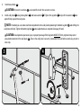
3. Insert two anchors
10
.
CAUTION: Be sure the anchors
10
are seated flush with the concrete surface.
4. Install wall plate
07
using two lag bolts
08
and two washers
09
. Tighten the lag bolts
08
only until the washers
09
are
pulled firmly against the wall plate.
NOTE: If needed, you can make small level adjustments to the wall plate by loosening the bottom lag bolt
08
and shifting the
wall plate until level. Tighten the bottom lag bolt
08
when adjustments are complete (see page 13 note).
CAUTION: Avoid potential personal injury or property damage! Both lag bolts MUST BE firmly tightened to prevent
unwanted movement of the wall plate
07
.
Ensure the wall plate is securely fastened to the wall before continuing on to the
next step.
07
10
08
09

16
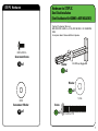
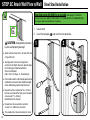
CAUTION: Avoid potential personal
injuries and property damage!
● Studs must be at least 2x4 in. (51 mm x 102 mm)
/ 25 ga. (0.6 mm)
● Stud type and structural strength must
conform to the North American Specification
for the Design of Cold-Formed Steel
Structural Members
[362 S 125 18, C-Shape, S - Stud Section].
● If back side of wall is unfinished, drywall must be
installed to a minimum of one stud left and right
of the stud(s) being used to install the mount.
● Drywall must be a minimum of 1/2 in. (13mm)
thick on each side of the studs, and a minimum
clearance of 1⅞ in. (48 mm)
behind the wall is required.
● Drywall must be secured to studs with
screws 12 in. (304.8 mm) on center.
● This product must be centered on the studs.
Min.
1/2 in.
(13 mm)
1
2
1. Locate stud.
2. Level the wall plate
07
and mark the hole locations.
Steel Stud Anchor Kit SSMK1 is not included
(see page 7) Contact
Customer Service: 800 359 5520 • EMEA: +31 (0) 800 056 2853 • UK: 0800 056 2853
to inquire about the additional hardware.
07
STEP 2C
Attach Wall Plate to Wall
Steel Stud Installation

17
25 mm
(1 in.)
13 mm
(1/2 in.)
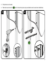
3
4
3. Drill pilot holes as illustrated.
4. Fold metal channel of anchor
S1
until it is flat with the plastic straps and slide the metal channel into the drilled hole.
S1

18
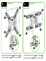
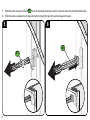
5
6
5. Hold the plastic straps of anchor
S1
by the end and pull towards you until the metal channel is flush behind the drywall.
6. Slide the plastic cap down the straps and into the hole with the lip of the cap flush against the wall.
S1
S1

19
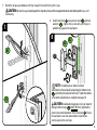
7
8
7. Bend the straps up and down until they snap off level with the lip of the cap.
CAUTION: Be sure the cap
is seated against the drywall surface and the snapped ends do not extend beyond the cap - cut if
neccessary.
8. Install wall plate
07
using two screws
S3
and two
washers
S2
. Tighten the screws only until they are
pulled firmly against the wall plate.
NOTE:
If needed, you can make small level
adjustments to the wall plate by loosening the bottom screw
S3
and shifting the wall plate until level. Tighten the bottom
screw when adjustments are complete (see page 13).
CAUTION:
Avoid potential personal injury or property
damage! Both screws
S3
MUST BE firmly tightened to
prevent unwanted movement of the wall plate
07
.
Ensure
the wall plate is securely fastened to the wall before
continuing on to the next step.
S1
S2
S3
S1
07

20
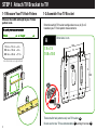
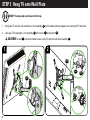
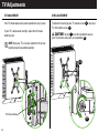
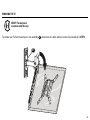
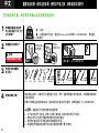
HEAVY! You may need assistance with this step.
STEP 3 Hang TV onto Wall Plate
1. Hang your TV onto the arm of wall plate / arm assembly
07
by first hooking the top support, then resting the TV into place.
2. Lock your TV to wall plate / arm assembly
07
with screw
11
and washer
12
.
CAUTION! Screw
11
must be installed to secure your TV onto the wall plate assembly
07
.
1
2
11
12
07
07
Sidan laddas...
Sidan laddas...
Sidan laddas...
Sidan laddas...
Sidan laddas...
Sidan laddas...
Sidan laddas...
Sidan laddas...
Sidan laddas...
Sidan laddas...
Sidan laddas...
Sidan laddas...
Sidan laddas...
Sidan laddas...
Sidan laddas...
Sidan laddas...
Sidan laddas...
Sidan laddas...
Sidan laddas...
Sidan laddas...
Sidan laddas...
Sidan laddas...
Sidan laddas...
Sidan laddas...
Sidan laddas...
Sidan laddas...
Sidan laddas...
Sidan laddas...
Sidan laddas...
Sidan laddas...
Sidan laddas...
Sidan laddas...
Sidan laddas...
Sidan laddas...
Sidan laddas...
Sidan laddas...
-
 1
1
-
 2
2
-
 3
3
-
 4
4
-
 5
5
-
 6
6
-
 7
7
-
 8
8
-
 9
9
-
 10
10
-
 11
11
-
 12
12
-
 13
13
-
 14
14
-
 15
15
-
 16
16
-
 17
17
-
 18
18
-
 19
19
-
 20
20
-
 21
21
-
 22
22
-
 23
23
-
 24
24
-
 25
25
-
 26
26
-
 27
27
-
 28
28
-
 29
29
-
 30
30
-
 31
31
-
 32
32
-
 33
33
-
 34
34
-
 35
35
-
 36
36
-
 37
37
-
 38
38
-
 39
39
-
 40
40
-
 41
41
-
 42
42
-
 43
43
-
 44
44
-
 45
45
-
 46
46
-
 47
47
-
 48
48
-
 49
49
-
 50
50
-
 51
51
-
 52
52
-
 53
53
-
 54
54
-
 55
55
-
 56
56


Secura QSF207 Installationsguide
- Kategori
- Platt skärmfästen
- Typ
- Installationsguide
på andra språk
- español: Secura QSF207 Guía de instalación
- Deutsch: Secura QSF207 Installationsanleitung
- français: Secura QSF207 Guide d'installation
- 日本語: Secura QSF207 インストールガイド
- English: Secura QSF207 Installation guide
- русский: Secura QSF207 Инструкция по установке
- Nederlands: Secura QSF207 Installatie gids