Tyco Visonic SMD-429 PG2 Series Installation And Operating Instructions Manual
- Typ
- Installation And Operating Instructions Manual

D-307865
SMD-429 PG2 Series Wireless Smoke
and Heat Detector
Installation and Operating Instructions
Read this instruction sheet thoroughly before installation and use of the SMD-429 PG2
Introduction
The SMD-429 PG2 is a wireless photoelectric smoke and heat detector with a fixed temperature
and rate of rise heat detector, and an internal piezoelectric alarm.
Three versions are available: a 915 MHz for US version (UL) and Canadian version (ULC), a
433 MHz and 868 MHz for International version (EU) and a 433 MHz for Australian version
(AUS).
Compatible Devices
The smoke detector is compatible with Visonic Control Panels and Power G receivers.
NOTE: For UL listed installations use only in conjunction with UL listed control panels: Power-
Master-10 and PowerMaster-30 PG2.
HUSH/TEST BUTTON
Operation
Approximately every 7 to 8 seconds the unit tests for a smoke or heat alarm condition. During
this sequence the unit also performs self diagnostics, and checks for tampers and faults. During
normal operation the green LED flashes every 60 seconds and the sounder does not sound.
Smoke Alarm
The smoke detector alarms when the signal level exceeds the “alarm” threshold and auto-
matically restores when the signal level falls below the alarm “restore” threshold. During an
alarm the red LED flashes once per second and the sounder sounds the evacuation temporal
pattern.
Alarm Silencing
This smoke alarm is provided with an automatically resettable alarm silencing feature. When the
sensor is in alarm, press the Test/Silence/Reset button to silence the local annunciation of the
alarm and transmit an alarm restore event to the control panel. The red LED flashes once per
second for up to 7 minutes, to indicate the alarm has been silenced.
After an alarm the red LED will flash once every 4 seconds to indicate an alarm in memory. The
alarm silence feature has a fixed time setting that desensitizes the smoke alarm for 7 minutes.
Alarm silencing does not disable the smoke alarm but rather reduces its smoke sensitivity. Fol-
lowing the silenced period the smoke alarm restores automatically to its intended operation. If
smoke around the unit is dense enough to suggest a potentially dangerous situation, it remains
in alarm, or may return to the alarm state quickly.
Detector Trouble
When the detector has a general fault, the yellow LED blinks once every four seconds and
there is a chirp every 48 seconds. After 4 hours, the panel will display a fire trouble message.
Detector and Status Indication

Status LEDs
Sounder
Normal Green flash every 60 seconds Off
Heat Alarm Red flash every 1 second ANSI S3.41 temporal 3
Heat Test Red flash every 1 second ANSI S3.41 temporal 3
Smoke Alarm Red flash every 1 second
ANSI S3.41 temporal 3
(press button to hush for 5-10
minutes)
Smoke Test
(with canned
smoke)
Red flash every 1 second
ANSI S3.41 temporal 3
(press button to hush for 5-10
minutes)
Test Alarm
(button press)
Red flash every 1 second ANSI S3.41 temporal 3
Detector
Trouble
Yellow flash every 4 seconds One chirp every 48 seconds
Low Battery Yellow flash every 12 seconds
One chirp every 48 seconds
(press button to hush for 12 hours)
Detector Dirty Yellow flash every 8 seconds One chirp every 48 seconds
Power-up Red, yellow, green, flash sequence
One chirp at the end of the power-
up sequence
Tamper
Red, yellow, green flash sequence every
12 seconds
Off
Hush Mode
Red flash every 1 second (alarm hush)
Off
Yellow flash every 12 seconds (low
battery hush)
Off
Detector Cleaning Required
When the detector is contaminated, the yellow LED blinks once every 8 seconds and there is a
chirp every 48 seconds. Refer to the MAINTENANCE section for cleaning the detector. After 4
hours, the panel displays a message fire clean.
Heat Alarm
The heat detector (cULus versions only) alarms when the heat signal level exceeds the heat
alarm threshold (135 ºF / 58 ºC); and will automatically restore when the heat signal level falls
below the heat alarm threshold (restore). The detector also goes into a heat alarm state when
there is a rapid increase in the temperature over a short period of time. During an alarm the
LED flashes 1/second and the sounder sounds the evacuation temporal pattern.
Tamper
The removal of the detector from the mounting plate initiates a “tamper” transmission. The
tamper condition is restored after the detector is mounted on the plate.
Wireless Transmissions
A supervisory message is transmitted at 128 second intervals for the SMD-429 PG2. If the sig-
nal is not received the control panel determines that the detector is missing.
The detector transmits the following:
l
Alarm / Alarm Restore - (heat or smoke alarm). Transmitted at time of occurrence.
NOTE: During an alarm condition, the detector sends an alarm event to the control panel.
When the condition is restored, the detector sends an alarm restore event to the
panel and sets the alarm restore indicator. The red LED blinks once every 4
seconds until the Alarm in memory is cleared. You can clear the alarm restore indic-
ator from the control panel, or press and hold the test button for 5 seconds.
l
Tamper / Tamper Restore - (tamper switch activated) 10 second maximum delay on restore
before transmission.
l
Low Battery - (battery voltage falls below threshold). Battery voltage is tested & transmitted
at the time of a supervisory or other transmissions.
l
Trouble - (detector fault or sensor compensation limit reached). Troubles are transmitted at
the time of occurrence (one trouble per supervisory interval).
Batteries
The wireless smoke heat alarm is powered by 3 AAA Duracell Procell PC2400 or 3 AAA Ener-
gizer E92 batteries (included). The detector regularly checks for a low battery. If a low battery is
detected, the transmitter sends a low battery message to the control panel, which displays the
detector's ID at low battery. In addition, the yellow LED of the detector blinks every 12 seconds.
The detector's sounder chirps every 48 seconds and the yellow LED continues to blink until the
batteries are replaced. Pressing the hush button silences the chirps for 12 hours, if no other
trouble conditions exist. The batteries should be replaced with new batteries when the chirps
begin.

At low battery, the test button is disabled. An alternative test method is to use an aerosol test
gas such as ‘Solo A10 smoke detector tester’. Shake the can well, aim it at the smoke detector
and spray a short burst (no more than 1 sec) at the detector. If the alarm does not sound,
repeat every 10 seconds until alarm sounds or for a maximum of 1 minute.
NOTE: If the alarm does not sound, contact the installer or dealer for service.
Battery Installation and Replacement
CAUTION: Risk of explosion if battery is replaced by an incorrect type. Dispose of used bat-
tery according to the manufacturer's instructions.
To replace batteries, complete the following steps:
1. Remove the detector from its mounting base by twisting the detector counterclockwise.
Carefully remove batteries by lifting from the “+” end using a flathead screwdriver and dis-
pose of them according to local regulations.
2. To ensure a proper power-down sequence, wait a minimum of 30 seconds before
installing new batteries.
3. Install 3 new AAA batteries, available from a local Duracell or Energizer dealer in the bat-
tery compartment. Install the batteries by inserting the “-” end first, then pushing the “+”
end down. If the batteries are incorrectly inserted, please remove them carefully by lifting
them out from the “+” end and correctly re-inserting them.
BATTERY COMPARTMENT
+
+
+
4. Re-install the detector on its mounting base by turning the detector clockwise until the mat-
ing marks align.
5. After the power-up sequence, the green LED should blink once every 60 seconds to indic-
ate normal operation. If the batteries are not installed correctly, the detector will not oper-
ate and the batteries may be damaged. If the detector does not power up, check that the
batteries are installed correctly and fully charged.
6. Test the detector as described later.
CONSTANT EXPOSURES TO HIGH OR LOW TEMPERATURES OR HIGH HUMIDITY MAY
REDUCE BATTERY LIFE.
Installation Instructions
The SMD-429 PG2 Series wireless smoke detector shall be installed and used within an envir-
onment that provides the pollution degree max 2 and over voltages category II in non-haz-
ardous locations, indoor only. The equipment is designed to be installed by SERVICE
PERSONS only; (SERVICE PERSON is defined as a person having the appropriate technical
training and experience necessary to be aware of hazards to which that person may be
exposed in performing a task and of measures to minimize the risks to that person or other per-
sons).
1. Smoke Detector Placement
Research has shown that all hostile fires in homes generate smoke to a greater or lesser extent.
Experiments with typical fires in homes indicate that detectable quantities of smoke precede
detectable levels of heat in most cases. For these reasons, smoke alarms should be installed
outside of each sleeping area and on each storey of the home.
The following information is for general guidance only and it is recommended that local fire
codes and regulations be consulted when locating and installing smoke alarms. It is recom-
mended that additional smoke alarms beyond those required for minimum protection be
installed. Additional areas that should be protected include: the basement; bedrooms, especially
where smokers sleep; dining rooms; furnace and utility rooms; and any hallways not protected
by the required units. On smooth ceilings, detectors may be spaced 9.1 m (30 ft) apart as a
guide. Other spacing may be required depending on ceiling height, air movement, the presence
of joists, uninsulated ceilings, etc. Consult National Fire Alarm Code NFPA 72, CAN/ULC-S553
or other appropriate national standards for installation recommendations.
l Do not locate smoke detectors at the top of peaked or gabled ceilings; the dead air space
in these locations may prevent the unit from detecting smoke.
l Avoid areas with turbulent air flow, such as near doors, fans or windows. Rapid air move-
ment around the detector may prevent smoke from entering the unit.
l Do not locate detectors in areas of high humidity.
l Do not locate detectors in areas where the temperature rises above 38 ºC (100 ºF) or falls
below 5 ºC (41 ºF).
l Smoke detectors must always be installed in USA in accordance with Chapter 29 of NFPA
72, the National Fire Alarm Code: 29.5.1.1.
Where required by applicable laws, codes, or standards for a specific type of occupancy,
approved single and multiple-station smoke alarms shall be installed as follows:

1. In all sleeping rooms and guest rooms.
2. Outside of each separate dwelling unit sleeping area, within 6.4 m (21 ft) of any door to a
sleeping room, the distance measured along a path of travel.
3. On every level of a dwelling unit, including basements.
4. On every level of a residential board and care occupancy (small facility), including base-
ments and excluding crawl spaces and unfinished attics.
5. In the living areas of a guest suite.
6. In the living areas of a residential board and care occupancy (small facility).
NOTE: In Australia the device shall not be installed in locations where the normal ambient
temperature is lower than 5 ºC or higher than 45 ºC.
2. Mount Smoke Detector Backplate
NOTE: The alarm device should only be installed by a competent engineer or technician.
Smoke detectors are not to be used with smoke detector guards unless the combination
has been evaluated and found suitable for that purpose.
Once a suitable location is found, mount the detector backplate. Install the mounting base on
the ceiling or on the wall (if local ordinances permit) using screw locations as required. Use the
two screws and anchors provided. Maneuver the base so the screws are at the elbow of the
screw slots and secure.
100 mm (4 in.) minimum
100 mm (4 in.)
minimum
3. Mounting
Fit the detector inside the base by aligning it over the base. The detector's alignment notch
should be slightly offset from the mounting base tamper release tab. Then turn the detector
clockwise until it clicks into place.
If there is a need to activate the built-in anti-tamper lock, carefully remove the breakaway tab on
the backplace as shown in the following figure.

Breakaway tab
4. Device Enrollment
The 7-digit serial number located on the back of the smoke detector housing must be enrolled
on the alarm systems control panel. See the Receiver Installation Manual and follow the enroll-
ment procedure. For placement tests remove the detector from its backplate for one second
(tamper) and then reattach. Wait at least 30 seconds for the test result before activating again.
A general description of the procedure is provided in the following flow chart:
Step
Procedure
1
See the Installation Manual for the alarm system that the device is being enrolled on, to
ensure that the proper steps are used.
2
Enter the Device Enrollment option through the specified method and select the
appropriate option to add the new device.
3
Enroll the device by inserting the batteries to power up the device and enter the Device
ID. For example, ID No. 202-XXXX.
NOTE: When enrolling the SMD-429 detector to PowerMaster panels with version 19.4
or lower, the detector will be enrolled as a Smoke and Heat detector ID 201-
xxxx, and labeled Smoke and Heat in the panel.
4
Select the desired Zone Number.
5
Configure any device parameters that are required. Enter the DEV SETTINGS menu
and select the required options to configure the detector:
Option Configuration Instructions
Burglary Siren Select to enable a burglary alarm.
Options: ON or OFF (default)
Fire Siren Select to enable a fire alarm.
Options: ON or OFF (default)
Gas / CO Siren Select to enable a gas alarm.
Options: ON or OFF (default)
Flood Siren Select to enable a flood alarm.
Fire Siren Options: ON or OFF (default
6
Mount and test the detector. See Smoke Detector Unit Test for information on testing the
device. In addition, see the alarm systems Installation Manual that the device is enrolled
on for other test procedures that are required.
5. Test Unit
NOTE: The central monitoring station if used, should be notified prior to the test being gen-
erated. This prevents a false alarm and an unnecessary response from the central mon-
itoring station.
Initiate test by pressing the test button for 5 seconds minimum. Alarm activation is indicated by
the flashing red LED, the sounder, and transmission of the alarm signal to the control panel.
The detector restores to normal when the test button is released.
NOTE: Allow a minimum of 20 seconds after power up and after test, alarm or tamper restore
activations.
NOTE: If the detector is in one of the following states when a test is initiated; it will not enter an
alarm state:
l Compensation Trouble
l Other internal faults that could prevent a smoke or heat alarm
Owner's Instructions
Fire Safety In The Home
Most fires occur in the home, and to minimize this danger, it is recommended that a household
fire safety audit be conducted and a family escape plan be developed.

Household Fire Safety Audit
1. Are all electrical appliances and outlets in safe condition? Check for frayed cords, over-
loaded lighting circuits, etc. If you are uncertain about the condition of your electrical appli-
ances or household service, have a professional evaluation.
2. Are all flammable liquids safely stored in closed containers, and in a cool and well vent-
ilated area? Cleaning the unit with flammable liquids should be avoided.
3. Are hazardous materials for example, matches out of the reach of children?
4. Are furnaces and wood burning appliances properly installed, clean, and in good working
order? If in doubt, have a professional evaluation.
Family Escape Planning
There is often very little time between the detection of a fire and the time it becomes deadly.
Because of this, it is very important that a family escape plan be developed and rehearsed.
l Every family member should participate in the escape plan.
l Study the possible escape routes from each location within the house. Since many fires
occur at night, special attention should be given to the escape routes from sleeping quar-
ters.
l It is essential that escape from a bedroom be possible without opening the interior door.
Consider the following when making your escape plans:
l Ensure that doors and windows that open to the outside are easily opened. Ensure that
they are not painted shut and that the locking mechanisms operate smoothly.
l If opening or using the exit is too difficult for children, the elderly or handicapped, plans for
their rescue should be developed. This plan includes making sure that those who are to per-
form the rescue can promptly hear the fire warning signal.
l If the exit is above the ground level, an approved fire ladder or rope should be provided, as
well as training in its use.
l Exits on the ground level should be kept clear. Be sure to remove snow from exterior patio
doors in the winter and that outdoor furniture or equipment does not block exits.
l The family should have a predetermined assembly point where everyone can be accounted
for; for example, across the street or at a neighbor’s house.
l Once everyone is out of the house, call the Fire Department.
l A good plan emphasizes a quick escape. Do not investigate first or attempt to fight the fire,
and do not attempt to rescue belongings or valuables as this takes up time. Once outside,
do not re-enter the house; wait for the Fire Department.
l Write the plan down and rehearse it frequently so that should an emergency ever arise,
everyone will know what to do. Revise the plan as conditions change; for example, when
there are more or fewer family members in the home or if there are changes to the house.
l Make sure your fire warning system is operational by conducting weekly tests. If you are
unsure about system operation, contact your smoke detector installer or dealer.
l It is recommended that you contact your local Fire Department and request further inform-
ation on home fire safety and escape planning. If available, have your local fire prevention
officer conduct an in-house fire safety inspection.
Testing Your Smoke Detector
Follow the test procedure described here or contact your smoke detector dealer or installer
for testing instructions. It is recommended to test the entire alarm system at least once a
week to verify the operation of all system functions.
Smoke Detector Unit Test
Initiate test by pressing the test button for 5 seconds, the sounder makes chirping noises during
this time. Press the button until the unit alarm sounds, an alarm should be sent to the control
panel. When the button is released, the alarm should cease. If this does not occur, ensure bat-
teries are the correct type, in good condition and are installed correctly.
Upon completing the functional testing of the smoke detector, check the unit’s sensing chamber
to ensure proper operation. To test the sensing chamber, use an aerosol test gas such as ‘Solo
A10 smoke detector tester’. Shake the can well, aim it at the smoke detector and spray a short
burst (no more than 1 second) at the detector. If the alarm does not sound, repeat every 10
seconds until alarm sounds or for a maximum of 1 minute. If the smoke detector does not func-
tion properly, call your smoke detector installer or dealer for service.
Smoke Detector Test
Before you test, complete the following steps:
1. Insert the battery and then mount the detector on the bracket before conducting the
smoke detector test.
2. After the battery is inserted, wait 2 minutes before testing it. The detector enters into Local
Diagnostic Test Mode for 15 minutes.
3. It is recommended to perform the Periodic Test and use either the Installer code (Installer
Diagnostic Mode) or the User code (User Diagnostic Mode) to test.
CAUTION: The diagnostic test cannot be performed when the tamper is open.
Press and hold the test button for 2 seconds. When the button is released, the following
sequence of events occur, the Red LED lights for 0.5 s > off for 0.5 s.
This is followed by 2 loud alarm beeps and at the same time the red LED flashes. In test mode,
the detector tests smoke, heat, and battery functions.

If the detector is in diagnostic mode, the detector performs the diagnostic test as described
below.
Sensitivity Indicating Means
If the detector is indicating ‘Detector Dirty’ with a Yellow LED flash every 8 seconds, a chirp
every 48 seconds and a fire clean message on the panel, the detector’s in built automatic drift
compensation feature is no longer able to compensate for dust and dirt accumulation and may
no longer be within the marked sensitivity. If the detector is indicating ‘Normal’ with Green LED
flash every 60 seconds it is within the marked sensitivity range.
NOTE: If the panel dispays the fire clean message after cleaning, call the installer or dealer for
service.
Diagnostic Test
The following sequence of events occur during a diagnostic test:
A. The detector performs a link quality test.
Note: The detector must be in local or diagnostic mode to perform the link quality test.
In diagnostic mode, if you press the test button for more than 6 seconds, an alarm mes-
sage is sent to the panel and a Temporal-3 alarm signal is sounded. After this sequence
is completed, the panel responds by sending an “Alarm in Memory” message to the
device.
B. At the end of the diagnostic test the LED blinks three times. The following table indicates
the received signal strength.
LED
Response
Green LED
blinks
Orange LED
blinks
Red LED
blinks
No blinks
Reception
Strong Good Poor
Paired, no
communicaton
IMPORTANT!Reliable reception must be confirmed. Therefore, "poor" signal strength is not
acceptable. If you receive a "poor" signal from the device, re-locate it and re-test until a "good"
or "strong" signal strength is received. For UL/CUL installations, the test results must be "strong".
See the alarm systems installation guide for detailed diagnostic tests.
Owner’s Maintenance
The smoke detector is designed to require minimum maintenance. If the case becomes dusty,
vacuum with a small brush attachment. If the case is greasy, wipe the case gently with a soft
cloth slightly dampened with soapy water.
Never disassemble the smoke detector; there are no user serviceable parts inside the unit.
You may only remove detector from backplate to replace batteries if not serviced by
installer. When replacing the batteries, follow the instructions specified in the Installation
Instructions.
Never paint the unit. Paint may prevent smoke from entering the unit. If you are planning
renovations or repainting, take precautions to avoid dust, paint or chemical contamination
to the detector.
If the unit is located in an area where it is exposed to high levels of dust or insects and causes
false alarms, it may require service; contact your smoke detector installer or dealer.
Testing and maintenance procedures shall be in accordance with CAN/ULC-S552-14.
Specifications
l
Regulatory Listings: UL268/ULC-S531 915 MHz
l
Diameter: 5 in (125 mm)
l
Height: 2.5 in (63 mm)
l
Weight (including battery): 8.75 oz (243 g)
l
Color: White
l
Spacing rating: 70 ft (21.3 m)
l
Alarm Sensitivity (threshold) 915 MHz (cULus): 1.26 - 2.39 %/ foot obscuration
l
Alarm Sensitivity (threshold) 433 MHz / 868 MHz: complies with EN14604
l
Audible Signal (ANSI Temporal 3): 85 dBA minimum in alarm
l
Sounder Alarm Pattern: 915 MHz only; Evacuation Temporal Pattern: 433 MHz EU/ 868
MHz
l
Operating Temperature: 40 ºF - 100 ºF (4.4 ºC - 37.8 ºC)
l
Operating Temperature with Heat Detector: 32 ºF - 100 ºF (0 ºC - 37.8 ºC)
l
Operating Temperature for Smoke Alarm:433 MHz 41 ºF - 113 ºF (5 ºC - 45 ºC); Type A
Photoelectric Smoke Alarm (Australia)
l
Humidity: 15 % - 90 % RH, non-condensing
l
Approved Batteries: 3 AAA Energizer E92 or Duracell Procell PC2400
l
Supervisory Transmission Frequency:915 MHz 64 minute intervals
l
Supervisory Transmission Frequency: 433 MHz / 868 MHz 12 minute intervals
l
Maximum Tx Power: 10 dBm @ 433 MHz, 14 dBm @ 868 MHz.
l
Low Battery Detection: Low battery 14 days remaining
WARRANTY
Visonic Limited (the “Manufacturer") warrants this product only (the "Product") to the original purchaser only (the “Purchaser”) against defective
workmanship and materials under normal use of the Product for a period of twelve (12) months from the date of shipment by the Manufacturer.
This Warranty is absolutely conditional upon the Product having been properly installed, maintained and operated under conditions of normal use in
accordance with the Manufacturers recommended installation and operation instructions. Products which have become defective for any other

reason, according to the Manufacturers discretion, such as improper installation, failure to follow recommended installation and operational instruc-
tions, neglect, willful damage, misuse or vandalism, accidental damage, alteration or tampering, or repair by anyone other than the manufacturer,
are not covered by this Warranty.
There is absolutely no warranty on software, and all software products are sold as a user license under the terms of the software license agree-
ment included with such Product.
The Manufacturer does not represent that this Product may not be compromised and/or circumvented or that the Product will prevent any death
and/or personal injury and/or damage to property resulting from burglary, robbery, fire or otherwise, or that the Product will in all cases provide
adequate warning or protection. The Product, properly installed and maintained, only reduces the risk of such events without warning and it is not a
guarantee or insurance that such events will not occur.
Conditions to Void Warranty: This warranty applies only to defects in parts and workmanship relating to normal use of the Products. It does not
cover:
* damage incurred in shipping or handling;
* damage caused by disaster such as fire, flood, wind, earthquake or lightning;
* damage due to causes beyond the control of the Seller such as excessive voltage, mechanical shock or water damage;
* damage caused by unauthorized attachment, alterations, modifications or foreign objects being used with or in conjunction with the Products;
* damage caused by peripherals (unless such peripherals were supplied by the Seller;
* defects caused by failure to provide a suitable installation environment for the products;
* damage caused by use of the Products for purposes other than those for which they were designed;
* damage from improper maintenance;
* damage arising out of any other abuse, mishandling or improper application of the Products.
Items Not Covered by Warranty: In addition to the items which void the Warranty, the following items shall not be covered by Warranty: (i) freight
cost to the repair centre; (ii) customs fees, taxes, or VAT that may be due; (iii) Products which are not identified with the Seller's product label and
lot number or serial number; (iv) Products disassembled or repaired in such a manner as to adversely affect performance or prevent adequate
inspection or testing to verify any warranty claim. Access cards or tags returned for replacement under warranty will be credited or replaced at the
Seller's option. THIS WARRANTY IS EXCLUSIVE AND EXPRESSLY IN LIEU OF ALL OTHER WARRANTIES, OBLIGATIONS OR LIABILITIES,
WHETHER WRITTEN, ORAL, EXPRESS OR IMPLIED, INCLUDING ANY WARRANTY OF MERCHANTABILITY OR FITNESS FOR A
PARTICULAR PURPOSE, OR OTHERWISE. IN NO CASE SHALL THE MANUFACTURER BE LIABLE TO ANYONE FOR ANY
CONSEQUENTIAL OR INCIDENTAL DAMAGES FOR BREACH OF THIS WARRANTY OR ANY OTHER WARRANTIES WHATSOEVER, AS
AFORESAID. THE MANUFACTURER SHALL IN NO EVENT BE LIABLE FOR ANY SPECIAL, INDIRECT, INCIDENTAL, CONSEQUENTIAL OR
PUNITIVE DAMAGES OR FOR LOSS, DAMAGE, OR EXPENSE, INCLUDING LOSS OF USE, PROFITS, REVENUE, OR GOODWILL,
DIRECTLY OR INDIRECTLY ARISING FROM PURCHASER’S USE OR INABILITY TO USE THE PRODUCT, OR FOR LOSS OR DESTRUCTION
OF OTHER PROPERTY OR FROM ANY OTHER CAUSE, EVEN IF MANUFACTURER HAS BEEN ADVISED OF THE POSSIBILITY OF SUCH
DAMAGE. THE MANUFACTURER SHALL HAVE NO LIABILITY FOR ANY DEATH, PERSONAL AND/OR BODILY INJURY AND/OR DAMAGE
TO PROPERTY OR OTHER LOSS WHETHER DIRECT, INDIRECT, INCIDENTAL, CONSEQUENTIAL OR OTHERWISE, BASED ON A CLAIM
THAT THE PRODUCT FAILED TO FUNCTION. HOWEVER, IF THE MANUFACTURER IS HELD LIABLE, WHETHER DIRECTLY OR
INDIRECTLY, FOR ANY LOSS OR DAMAGE ARISING UNDER THIS LIMITED WARRANTY, THE MANUFACTURER'S MAXIMUM LIABILITY (IF
ANY) SHALL NOT IN ANY CASE EXCEED THE PURCHASE PRICE OF THE PRODUCT INVOLVED, WHICH SHALL BE FIXED AS
LIQUIDATED DAMAGES AND NOT AS A PENALTY, AND SHALL BE THE COMPLETE AND EXCLUSIVE REMEDY AGAINST THE
MANUFACTURER. SOME JURISDICTIONS DO NOT ALLOW THE EXCLUSION OR LIMITATION OF INCIDENTAL OR CONSEQUENTIAL
DAMAGES, SO THESE LIMITATIONS MAY NOT APPLY UNDER CERTAIN CIRCUMSTANCES.
When accepting the delivery of the Product, the Purchaser agrees to the said conditions of sale and warranty and he recognizes having been
informed of.
The Manufacturer shall be under no liability whatsoever arising out of the corruption and/or malfunctioning of any telecommunication or electronic
equipment or any programs.
The Manufacturers obligations under this Warranty are limited solely to repair and/or replace at the Manufacturer’s discretion any Product or part
thereof that may prove defective. Any repair and/or replacement shall not extend the original Warranty period. The Manufacturer shall not be
responsible for dismantling and/or reinstallation costs. To exercise this Warranty the Product must be returned to the Manufacturer freight pre- paid
and insured. All freight and insurance costs are the responsibility of the Purchaser and are not included in this Warranty.
This warranty shall not be modified, varied or extended, and the Manufacturer does not authorize any person to act on its behalf in the modification,
variation or extension of this warranty. This warranty shall apply to the Product only. All products, accessories or attachments of others used in
conjunction with the Product, including batteries, shall be covered solely by their own warranty, if any. The Manufacturer shall not be liable for any
damage or loss whatsoever, whether directly, indirectly, incidentally, consequentially or otherwise, caused by the malfunction of the Product due to
products, accessories, or attachments of others, including batteries, used in conjunction with the Products. This Warranty is exclusive to the ori-
ginal Purchaser and is not assignable.
This Warranty is in addition to and does not affect your legal rights. Any provision in this warranty which is contrary to the Law in the state or coun-
try were the Product is supplied shall not apply.
Governing Law: This disclaimer of warranties and limited warranty are governed by the domestic laws of Israel.
Warning
The user must follow the Manufacturer’s installation and operational instructions including testing the Product and its whole system at least once a
week and to take all necessary precautions for his/her safety and the protection of his/her property.
* In case of a conflict, contradiction or interpretation between the English version of the warranty and other versions, the English version shall pre-
vail.
END-USER LICENSE AGREEMENT
IMPORTANT - READ THIS END- USER LICENSE AGREEMENT ("EULA") CAREFULLY BEFORE OPENING THE DISK PACKAGE,
DOWNLOADING THE SOFTWARE OR INSTALLING, COPYING OR OTHERWISE USING THE SOFTWARE.
THIS EULA IS A LEGAL AGREEMENT BETWEEN YOU AND VISONIC LTD. (“TYCO”) AND GOVERNS YOUR USE OF THE SOFTWARE
ACCOMPANYING THIS EULA, WHICH SOFTWARE INCLUDES COMPUTER SOFTWARE AND MAY INCLUDE MEDIA, PRINTED MATERIALS,
AND "ON-LINE" OR ELECTRONIC DOCUMENTATION (COLLECTIVELY, THE "SOFTWARE"). BY BREAKING THE SEAL ON THIS PACKAGE,
DOWNLOADING THE SOFTWARE OR INSTALLING, COPYING OR OTHERWISE USING THE SOFTWARE, YOU AGREE TO BE BOUND BY THE
TERMS OF THIS EULA. IF YOU DO NOT AGREE TO ALL OF THE TERMS AND CONDITIONS OF THIS EULA, DO NOT OPEN, DOWNLOAD,
INSTALL, COPY OR OTHERWISE USE THE SOFTWARE.
1. SCOPE OF LICENSE. The Software may include computer code, program files and any associated media, hardware or software keys,
printed material and electronic documentation. The Software may be provided to you pre-installed on a storage device (the media) as part
of a computer system or other hardware or device (“System”). The Software is protected by copyright laws and international copyright
treaties, as well as other intellectual property laws and treaties. All title and intellectual property rights in and to the Software (including but
not limited to any images, photographs, and text incorporated into the Software), the accompanying printed materials, and any copies of
the Software, are owned by Tyco and/or its suppliers. The Software is licensed, not sold. All rights not expressly granted under this EULA
are reserved by Tyco and its suppliers.
2. GRANT OF LICENSE. This EULA grants you the following rights on a non-exclusive basis:
1. General. This EULA permits you to use the Software for which you have purchased this EULA. Once you have purchased licenses for the
number of copies of the Software that you require, you may use the Software and accompanying material provided that you install and
use no more than the licensed number of copies at one time. The Software is only licensed for use with specified Licensor-supplied Sys-
tems. If the Software is protected by a software or hardware key or other device, the Software may be used on any computer on which
the key is installed. If the key locks the Software to a particular System, the Software may only be used on that System.
2. Locally Stored Components. The Software may include a software code component that may be stored and operated locally on one or
more devices. Once you have paid the required license fees for these devices (as determined by Tyco in its sole discretion), you may
install and/or use one copy of such component of the Software on each of the devices as licensed by Tyco. You may then use, access,
display, run or otherwise interact with ("use") such component of the Software in connection with operating the device on which it is
installed solely in the manner set forth in any accompanying documentation or, in the absence of such, solely in the manner contemplated
by the nature of the Software.
3. Remotely Stored Components. The Software may also include a software code component for operating one or more devices remotely.
You may install and/or use one copy of such component of the Software on a remote storage device on an internal network with all of the
devices and may operate such component with each device over the internal network solely in the manner set forth in any accompanying
documentation or, in the absence of such, solely in the manner contemplated by the nature of the Software; provided however, you must
still acquire the required number of licenses for each of the devices with which such component is to be operated.
4. Embedded Software/Firmware. The Software may also include a software code component that is resident in a device as provided by
Tyco for operating that device. You may use such component of the Software solely in connection with the use of that device, but may
not retrieve, copy or otherwise transfer that software component to any other media or device without Tyco's express prior written author-
ization.
5. Backup Copy. You may make a back-up copy of the Software (other than embedded software) solely for archival purposes, which copy
may only be used to replace a component of the Software for which you have current valid license. Except as expressly provided in this
EULA, you may not otherwise make copies of the Software, including the printed materials.
3. OTHER RIGHTS AND LIMITATIONS. Your use of the Software is subject to the following additional limitations. Failure to comply with any
of these restrictions will result in automatic termination of this EULA and will make available to Tyco other legal remedies.
1. Limitations on Reverse Engineering and Derivative Works. You may not reverse engineer, decompile, or disassemble the Software, and
any attempt to do so shall immediately terminate this EULA - except and only to the extent that such activity may be expressly permitted
by applicable law notwithstanding this limitation. You may not make any changes or modifications to any portion of the Software, or create
any derivative works, without the written permission of an officer of Tyco (except as provided in Section 3(f) of this EULA with respect to

“open source” software). You may not remove any proprietary notices, marks or labels from the Software. You shall institute reasonable
measures to ensure compliance with the terms and conditions of this EULA by your personnel and agents.
2. Copyright Notices. You must maintain all copyright notices on all copies of the Software.
3. Transfer. You may only transfer your rights under this EULA (i) as part of a permanent sale or transfer of all of the devices for which the
Software is licensed as applicable; (ii) if you transfer all of the Software (including all component parts, the media and printed materials,
any upgrades and this EULA); (iii) if you do not retain any copies of any portion of the Software; (iv) if the recipient agrees to the terms
of this EULA; and (v) if the Software is an upgrade, such transfer must also include all prior versions of the Software. You agree that fail-
ure to meet all of these conditions renders such transfer null and void.
4. Termination. Without prejudice to any other rights, Tyco may terminate this EULA if you fail to comply with the terms and conditions
herein. In such event, you must immediately destroy all copies of the Software and all of its component parts. To the extent the Soft-
ware is embedded in hardware or firmware, you will provide prompt access to Tyco or its representative to remove or lock Software fea-
tures or functionality as Tyco determines.
5. Subsequent EULA. Tyco may also supersede this EULA with a subsequent EULA pursuant to providing you with any future component,
release, upgrade or other modification or addition to the Software. Similarly, to the extent that the terms of this EULA conflict with any
prior EULA or other agreement between you and Tyco regarding the Software, the terms of this EULA shall prevail.
6. Incorporation of “Open Source” and other Third Party Software. Portions of the Software may be subject to certain third party license
agreements governing the use, copying, modification, redistribution and warranty of those portions of the Software, including what is com-
monly known as “open source” software. A copy of each applicable third party license can be found in the file README.TXT or other doc-
umentation accompanying the Software. Such open source software is not subject to any warranty and indemnity set forth in this EULA.
By using the Software you are also agreeing to be bound to the terms of such third party licenses. If provided for in the applicable third
party license, you have a right to receive source code for such software for use and distribution in any program that you create, so long
as you in turn agree to be bound to the terms of the applicable third party license, and your programs are distributed under the terms of
that license. A copy of such source code may be obtained free of charge by contacting your Tyco representative.
7. Trademarks. This EULA does not grant you any rights in connection with any trademarks or service marks of Tyco, its affiliates or its sup-
pliers.
8. Rental. You may not sublicense, rent, lease or lend the Software. You may not make it available to others or post it on a server or web
site or otherwise distribute it.
9. Software Keys. The hardware/software key, where applicable, is your proof of license to exercise the rights granted herein and must be
retained by you. Lost or stolen keys will not be replaced.
10. Demonstration and Evaluation Copies. A demonstration or evaluation copy of the Software is covered by this EULA; provided that the
licenses contained herein shall expire at the end of the demonstration or evaluation period.
11. Registration of Software. The Software may require registration with Tyco prior to use. If you do not register the Software, this EULA is
automatically terminated and you may not use the Software.
12. Additional Restrictions. The Software may be subject to additional restrictions and conditions on use as specified in the documentation
accompanying such Software, which additional restrictions and conditions are hereby incorporated into and made a part of this EULA.
13. Upgrades and Updates. To the extent Tyco makes them available, Software upgrades and updates may only be used to replace all or part
of the original Software that you are licensed to use. Software upgrades and updates do not increase the number of copies licensed to
you. If the Software is an upgrade of a component of a package of Software programs that you licensed as a single product, the Soft-
ware may be used and transferred only as part of that single product package and may not be separated for use on more than one com-
puter or System. Software upgrades and updates downloaded free of charge via a Tyco authorized World Wide Web or FTP site may be
used to upgrade multiple Systems provided that you are licensed to use the original Software on those Systems.
14. Tools and Utilities. Software distributed via a Tyco-authorized World Wide Web or FTP site (or similar Tyco-authorized distribution means)
as a tool or utility may be copied and installed without limitation provided that the Software is not distributed or sold and the Software is
only used for the intended purpose of the tool or utility and in conjunction with Tyco products. All other terms and conditions of this EULA
continue to apply.
15. EXPORT RESTRICTIONS. You agree that you will not export, re-export or transfer any portion of the Software, or any direct product
thereof (the foregoing collectively referred to as the "Restricted Components"), to IRAN, NORTH KOREA, SYRIA, CUBA and SUDAN,
including any entities or persons in those countries, either directly or indirectly (“Tyco’s Position”). You also agree that you will not export,
re-export or transfer the Restricted Components to any other countries except in full compliance with all applicable governmental require-
ments, including but not limited to applicable economic sanctions and constraints administered by any Israeli governmental authority, includ-
ing, but not limited to the Israeli Ministry of Defense, by any applicable treaty, applicable export control measures administered by Israel ,
U.S. Treasury Department and applicable export control measures administered by the U.S. Department of Commerce and U.S. Depart-
ment of State, any other U.S. government agencies, and measures administered by the European Union or the government agencies of
any other countries. Any violation by you of the applicable laws or regulations of the U.S. or any other government, or where you breach
Tyco’s Position notwithstanding whether or not this is contrary to any aforementioned applicable laws or regulations, will result in automatic
termination of this EULA.
16. U.S. GOVERNMENT RESTRICTED RIGHTS. The Software is Commercial Computer Software provided with "restricted rights" under
Federal Acquisition Regulations and agency supplements to them. Any use, duplication or disclosure by the U.S. Government is subject to
restrictions as set forth in subparagraph (c)(1)(ii) of the Rights in Technical Data and Computer Software clause at DFAR 255.227-7013
et. seq. or 252.211-7015, or subparagraphs (a) through (d) of the Commercial Computer Software Restricted Rights at FAR 52.227-19,
as applicable, or similar clauses in the NASA FAR Supplement. Contractor/manufacturer is Visonic Ltd., 24 Habarzel St., Tel-Aviv, Israel
69710.
17. LIMITATION OF LIABILITY & EXCLUSION OF DAMAGES.
1. LIMITATION OF LIABILITY. IN NO EVENT WILL TYCO’S AGGREGATE LIABILITY (INCLUDING, BUT NOT LIMITED TO, LIABILITY
FOR NEGLIGENCE, STRICT LIABILITY, BREACH OF CONTRACT, MISREPRESENTATION AND OTHER CONTRACT OR TORT
CLAIMS) ARISING FROM OR RELATED TO THIS EULA, OR THE USE OF THE SOFTWARE, EXCEED THE AMOUNT OF FEES YOU
PAID TO TYCO OR ITS RESELLER FOR THE SOFTWARE THAT GIVES RISE TO SUCH LIABILITY. BECAUSE AND TO THE EXTENT
THAT SOME JURISDICTIONS DO NOT ALLOW THE EXCLUSIONS OR LIMITATIONS OF LIABILITY ABOVE, THESE MAY NOT
APPLY TO YOU.
2. EXCLUSION OF OTHER DAMAGES. UNDER NO CIRCUMSTANCES SHALL TYCO OR ANY OF ITS RESELLERS OR LICENSORS BE
LIABLE FOR ANY OF THE FOLLOWING: (I) THIRD PARTY CLAIMS; (II) LOSS OR DAMAGE TO ANY SYSTEMS, RECORDS OR
DATA, OR LIABILITIES RELATED TO A VIOLATION OF AN INDIVIDUAL'S PRIVACY RIGHTS; OR (III) INDIRECT, INCIDENTAL,
SPECIAL, CONSEQUENTIAL, PUNITIVE, RELIANCE, OR COVER DAMAGES (INCLUDING WITHOUT LIMITATION, LOSS OF
PROFITS, BUSINESS INTERRUPTION, LOSS OF DATA OR BUSINESS INFORMATION AND LOST SAVINGS), IN EACH CASE
EVEN IF TYCO HAS BEEN ADVISED OF THE POSSIBILITY OF SUCH DAMAGES. YOU ARE SOLELY RESPONSIBLE AND LIABLE
FOR VERIFYING THE SECURITY, ACCURACY AND ADEQUACY OF ANY OUTPUT FROM THE SOFTWARE, AND FOR ANY
RELIANCE THEREON. SOME JURISDICTIONS DO NOT ALLOW THE EXCLUSION OF INCIDENTAL OR CONSEQUENTIAL
DAMAGES, OR THE LIMITATION ON HOW LONG AN IMPLIED WARRANTY LASTS, SO SOME OF THE ABOVE LIMITATIONS MAY
APPLY TO YOU ONLY TO THE EXTENT PERMITTED BY THOSE LAWS.
GENERAL. If any provision of this EULA is found to be unlawful, void, or for any reason unenforceable, then that provision shall be severed from
this EULA and shall not affect the validity and enforceability of the remaining provisions. You should retain proof of the license fee paid, including
model number, serial number and date of payment, and present such proof of payment when seeking service or assistance covered by the war-
ranty set forth in this EULA. This EULA is governed by the laws of Israel, without giving effect to any choice or conflict of law provision or rule that
would cause the application of the laws of any jurisdiction other than Israel. Each of the Parties submits to the exclusive jurisdiction of any court sit-
ting in Tel Aviv, Israel for purposes of resolving any and all disputes arising under or related to these terms and conditions. The parties specifically
exclude the application of the provisions of the United Nations Convention on Contracts for the International Sale of Goods.
To read this End-User License Agreement in other languages, please go to www.visonic.com
Regulatory Information
The smoke alarm SMD-429 PG2 has a recommended service life of 10 years under normal conditions of use. Please refer to
the label applied to the device indicating the recommended replacement year.
NOTE: In Australia, the device shall not be installed in locations where the normal ambient temperature is lower than 41°F
(5°C) or higher than 113°F (45°C).
This manual shall be used in conjunction with the Installation Manual of the alarm control panel. All the instructions specified
within that manual must be observed.
FCC and IC Compliance Statement
CAUTION: Changes or modifications not expressly approved by Visonic could void your authority to use this equipment.
The letters “IC:” indicate that this is an Innovation, Science and Economic Development Canada’s certification number.
This device complies with FCC Rules Part 15 and with Industry Canada licence-exempt RSS standard(s). Operation is subject
to two conditions: (1) This device may not cause harmful interference, and (2) this device must accept any interference that
may be received or that may cause undesired operation.
For Industry Canada: Le présent appareil est conforme aux CNR d'ISED Canada applicables aux appareils radio exempts de
licence. L'exploitation est autorisée aux deux conditions suivantes : (1) l'appareil ne doit pas produire de brouillage, et (2) l'util-
isateur de l'appareil doit accepter tout brouillage radioélectrique subi, même si le brouillage est susceptible d'en compromettre
le fonctionnement.
This Class B digital apparatus complies with Canadian ICES-003.
Cet appareil numerique de la classe B est conforme a la norme NMB-003 du Canada.
CAN ICES-3 (B)/NMB-3(B)

WARNING! To comply with FCC and IC RF exposure compliance requirements, the device should be located at a distance
of at least 20 cm from all persons during normal operation. The antennas used for this product must not be co-located or
operated in conjunction with any other antenna or transmitter.
Avertissement! Le dispositif doit être placé à une distance d'au moins 20 cm à partir de toutes les personnes au cours de
son fonctionnement normal. Les antennes utilisées pour ce produit ne doivent pas être situés ou exploités conjointement
avec une autre antenne ou transmetteur.
NOTE: This equipment has been tested and found to comply with the limits for a Class B digital device, pursuant to part 15 of
the FCC Rules. These limits are designed to provide reasonable protection against harmful interference in a residential install-
ation. This equipment generates, uses and can radiate radio frequency energy and, if not installed and used in accordance
with the instructions, may cause harmful interference to radio communications. However, there is no guarantee that inter-
ference will not occur in a particular installation. If this equipment does cause harmful interference to radio or television recep-
tion, which can be determined by turning the equipment off and on, the user is encouraged to try to correct the interference
by one or more of the following measures:
l Re-orient the receiving antenna
l Relocate the alarm control with respect to the receiver
l Move the alarm control away from the receiver
l Connect the alarm control into a different outlet so that alarm control and receiver are on different circuits.
l Consult the dealer r or an experienced radio/television technician for help.
WARNING! Changes or modifications to this equipment not expressly approved by the party responsible for compliance
(Visonic Ltd.) could void the user’s authority to operate the equipment.
Notified Body BSI (2797)
Visonic Ltd., Tel-Aviv, Israel.
EN14604: 2005/AC:2008
2019
2797-CPR-713754
Smoke Alarm Device
Hereby, Visonic Ltd. declares that the radio equipment type SMD-429 PG2 is in compliance with Directive
2014/53/EU.
The full text of the EU declaration of conformity is available at the following internet address: http://www.vi-
sonic.com/download-center.

Installations- og betjeningsvejledning
Læs denne brugsanvisning grundigt inden installation og brug af SMD-429 PG2
Introduktion
SMD-429 PG2er en trådløs fotoelektrisk røg- og varmedetektor med en fastlagt temperaturs- og
stigningshastighedsvarmedetektor og en intern piezoelektrisk alarm.
Der findes tre versioner: en 915 MHz til den amerikanske version (UL) og den canadiske ver-
sion (ULC), en 433 MHz og 868 MHz til den internationale version (EU) og en 433 MHz til den
australske version (AUS) .
Kompatible enheder
Røgdetektoren er kompatibel med Visonic-kontrolpaneler og Power G-modtagere.
BEMÆRK: Til installationer på UL-oversigten må den kun anvendes sammen med kon-
trolpaneler på UL-oversigten: PowerMaster-10 og PowerMaster-30 PG2.
TYS/TEST-KNAP
Betjening
Cirka hver 7-8. sekund tester enheden for en røg- eller varmealarmtilstand. Under denne
sekvens udfører enheden også selvdiagnostik og kontrollerer sabotager og fejl. Under normal
drift blinker den grønne LED hver 60. sekund, og lydgiveren siger ikke noget.
Røgalarm
Røgdetektoren alarmerer, når signalniveauet overskrider "alarm"-tærskelværdien og gendannes
automatisk, når signalniveauet falder til under alarm-"gendannelses" tærskelværdien. Under en
alarm blinker LED'en rødt én gang i sekundet, og lydgiveren afgiver alarmmønsteret for evaku-
ering.
Alarmafbrydelse
Denne røgalarm er forsynet med en automatisk genindstillelig alarmafbrydelsesfunktion. Når
sensoren er i alarm, skal du trykke på tasten Test/Silence/Reset for at afbryde den lokale bebu-
delse af alarmen og sende en alarmgendannelseshændelse til kontrolpanelet. Den røde LED
blinker 1 gang i sekundet i op til 7 minutter for at indikere, at alarmen er blevet afbrudt.
Efter en alarm vil den røde LED blinke 1 gang hvert 4. sekund for at indikere, at der er en
alarm i hukommelsen. Alarmafbrydelsesfunktionen har en fast tidsindstilling, der desensibiliserer
røgalarmen i 7 minutter.
Alarmafbrydelse deaktiverer ikke røgalarmen, men reducerer dens røgfølsomhed. Efter afbry-
delsesperioden genoprettes røgalarmen automatisk til den påtænkte drift. Hvis røg omkring
enheden er tæt nok til at antyde en potentielt farlig situation, forbliver den i alarm eller kan hur-
tigt gå tilbage til alarmtilstanden.
Detektorproblemer
Når detektoren har en generel fejl, blinker den gule LED en gang hvert fjerde sekund, og der
er et bip hver gang, der er gået 48 sekunder. Efter 4 timer viser panelet en besked om brand-
fejl.
Detektor og statusindikation
Status LEDer
Lydgiver
normal Grønt blink hver 60. sekund Fra
Varmealarm Rødt blink hvert sekund ANSI S3.41 temporal 3
Varmetest Rødt blink hvert sekund ANSI S3.41 temporal 3
Røgalarm Rødt blink hvert sekund
ANSI S3.41 temporal 3
(tryk på knappen for at dæmpe i 5-
10 minutter)
SMD-429 PG2 Serie Trådløs røg- og varmedetektor

Status LEDer
Lydgiver
Røgtest
(med røg fra
dåse)
Rødt blink hvert sekund
ANSI S3.41 temporal 3
(tryk på knappen for at tysse i 5-10
minutter)
Testalarm
(tryk på knap)
Rødt blink hvert sekund ANSI S3.41 temporal 3
Detektorproblemer Gult blink hvert 4. sekund
Et bip hver gang der er gået 48
sekunder
Lavt batteri Gult blink hvert 12. sekund
Et bip hvert 48- sekund
(tryk på knappen for at dæmpe i 12
timer)
Detektor beskidt Gult blink hvert 8. sekund
Et bip hver gang der er gået 48
sekunder
Opstart Rød, gul, grøn blinkesekvens
Ét bip i slutningen af
opstartssekvensen
Sabotage
Rød, gul, grøn blinkesekvens hvert
12. sekund
Fra
Dæmpet tilstand
Rødt blink hvert sekund (dæmpet
alarm)
Fra
Gult blink hvert 12. sekund (lavt
batteri dæmpet)
Fra
Rengøring af detektor er påkrævet
Når detektoren er beskidt, blinker den gule LED en gang hvert 8 sekund, og der er et bip hver
gang, der er gået 48 sekunder. Se afsnittet VEDLIGEHOLDELSE for rengøring af detektoren.
Efter 4 timer viser panelet en besked om brandrens.
Varmealarm
Varmedetektoren (kun cULus-versioner) alarmerer, når varmesignalniveauet overskrider var-
mealarmtærskelværdien (58 ºC); og vil automatisk gendannes, når varmesignalniveauet falder til
under varmealarmtærskelværdien (gendannelse). Detektoren går også ind i en var-
malarmtilstand, når der sker en hurtig stigning i temperaturen over en kort periode. Under en
alarm blinker LED'en 1 gang/sekundet, og lydgiveren afgiver det temporale mønster for evaku-
ering.
Sabotage
Fjernelsen af detektoren fra monteringspladen igangsætter en "sabotage"-transmission. Sabo-
tagetilstanden genskabes, efter detektoren monteres på pladen.
Trådløse transmissioner
En tilsynsmeddelelse transmitteres med 128 sekunder intervaller for SMD-429 PG2. Hvis sig-
nalet ikke modtages, fastslår kontrolpanelet, at detektoren mangler.
Detektoren transmitterer følgende:
l
Alarm/alarmgendannelse – (varme- eller røgalarm). Transmitteres på tidspunktet for fore-
komsten.
BEMÆRK: Under en alarmtilstand sender detektoren en alarmhændelse til kontrolpanelet.
Når tilstanden genoprettes, sender detektoren en alarmgendannelsesbegivenhed til
panelet og indstiller alarmgendannelsesindikatoren. Den røde LED blinker 1 gang
hvert 4. sekund, indtil Alarm i hukommelse bliver ryddet. Du kan slette alarm-
gendannelsesindikatoren fra kontrolpanelet, eller trykke på testknappen og holde
den nede i 5 sekunder.
l
Sabotage/sabotage gendannelse – (sabotagekontakt aktiveret) 10 sekunders maksimal for-
sinkelse ved gendannelse før transmission.
l
Lavt batteri – (batterispænding falder under tærskelværdi). Batterispændingen testes og
transmitteres under et tilsyn eller andre transmissioner.
l
Problem – (detektorfejl eller sensorkompensationsgrænse nået). Problemer transmitteres på
tidspunktet for forekomsten (ét problem pr. tilsynsinterval).
Batterier
Den trådløse røgvarmealarm drives af 3 AAA Duracell Procell PC2400 eller 3 AAA Energizer
E92-batterier (inkluderet). Detektoren kontrollerer regelmæssigt for lavt batteri. Hvis der opdages
et lavt batteri, sender senderen en besked om lavt batteri til kontrolpanelet, som viser detek-
torens ID med lavt batteri. Derudover blinker den gule LED fra detektoren hvert 12. sekund.
Detektorens lydgiver bipper hvert 48. sekund, og den gule LED fortsætter med at blinke, indtil
batterierne bliver udskiftet. Ved at trykke på tysse-knappen afbrydes bippene i 12 timer, hvis der
ikke er andre problemer. Batterierne skal udskiftes med nye batterier, når bippene begynder.
Ved lavt batteri deaktiveres testknappen. En anden testmetode er at bruge en aerosol-testgas,
som ‘Solo A10 smoke detector tester’. Ryst dåsen godt, peg ind mod røgdetektoren og spray
kort (ikke mere end 1 sekund) ind mod detektoren. Hvis alarmen ikke går i gang, gentag da
hvert 10. sekund, indtil alarmen lyder, eller maks. 1 minut.

BEMÆRK: Hvis alarmen ikke går i gang, skal du kontakte installatøren eller forhandleren for at
få et eftersyn.
Installation og udskiftning af batterier
FORSIGTIG: Eksplosionsrisiko hvis batteriet udskiftes med en forkert type. Bortskaf brugte
batterier i henhold til producentens anvisninger.
For at udskifte batterier skal følgende trin udføres:
1. Fjern detektoren fra dens monteringsbase ved at dreje detektoren mod uret. Fjern for-
sigtigt batterierne ved at løfte fra enden "+" ved hjælp af en flad skruetrækker, og bortskaf
dem i henhold til lokale regler.
2. For at sikre en ordentlig nedlukningssekvens skal du vente mindst 30 sekunder, inden du
isætter nye batterier.
3. Isæt 3 nye AAA-batterier, som fås hos en lokal Duracell- eller Energizer-forhandler, i bat-
terirummet. Isæt batterierne ved at indsætte enden "-" først og derefter trykke enden "+"
ned. Hvis batterierne sættes forkert i, skal du fjerne dem forsigtigt ved at løfte dem ud fra
"+" enden og sætte dem korrekt i igen.
BATTERIRUM
4. Genmontér detektoren på dens monteringsbase ved at dreje detektoren med uret, indtil
parringsmærkerne mødes.
5. Efter opstartssekvensen skal den grønne LED blinke en gang hvert 60. sekund for at indi-
kere normal drift. Hvis batterierne ikke er sat korrekt i, vil detektoren ikke virke, og bat-
terierne kan blive beskadiget. Hvis detektoren ikke opstarter, skal du kontrollere, at
batterierne er installeret korrekt og fuldt opladet.
6. Test detektoren som senere beskrevet.
KONSTANTE EKSPONERINGER FOR HØJE ELLER LAVE TEMPERATURER ELLER HØJ
LUFTFUGTIGHED KAN REDUCERE BATTERIETS LEVETID.
Installationsvejledning
Serien SMD-429 PG2 af trådløse røgdetektorer skal installeres og anvendes i et miljø, der højst
har forureningsgraden 2 og over spændinger i kategori II på ikke-farlige steder, og kun inden-
dørs. Udstyret er designet til kun at blive installeret af SERVICEPERSONALE;
(SERVICEPERSONALE er defineret som en person, der har den passende tekniske uddan-
nelse og erfaring, som er nødvendig for at være opmærksom på risici, som denne person kan
blive udsat for ved udførelse af en opgave og på foranstaltninger til at minimere risici for denne
person eller andre personer).
1. Røgdetektorens placering
Forskning har vist, at alle fjendtlige brande i hjemmet skaber røg i større eller mindre grad. Eks-
perimenter med typiske brande i boliger viser, at detekterbare mængder af røg går forud for
detekterbare niveauer af varme i de fleste tilfælde. Af disse årsager bør der installeres røga-
larmer uden for hvert soveområde og på hver etage i hjemmet.
Følgende oplysninger er kun vejledende, og det anbefales at undersøge lokale brandkoder og
-regler ved lokalisering og installation af røgalarmer. Det anbefales, at der installeres ekstra
røgalarmer ud over dem, der kræves for minimal beskyttelse. Yderligere områder, der bør
beskyttes, omfatter: kælderen; soveværelser, især hvor rygere sover; spisestuer; ovn og bryg-
gers; og alle gange der ikke er beskyttet af de påkrævede enheder. På glatte lofter kan detek-
torer være adskilt 9,1 m fra hinanden som udgangspunkt. Andre afstande kan være påkrævet
afhængigt af loftshøjde, luftens bevægelser, tilstedeværelse af bjælker, uisolerede lofter osv.
Kontakt National Fire Alarm Code NFPA 72, CAN/ULC-S553 eller andre relevante nationale
standarder for installationsanbefalinger.
l Du må ikke placere røgdetektorer i den øverste del af spidse eller gavlede lofter; det døde
luftrum på disse steder kan forhindre enheden i at detektere røg.
l Undgå områder med turbulent luftstrøm som f.eks. nær døre, ventilatorer eller vinduer. Hur-
tig luftbevægelse omkring detektoren kan forhindre røg i at komme ind i enheden.
l Lad være med at placere detektorer i områder med høj luftfugtighed.
l Lad være med at placere detektorer i områder, hvor temperaturen bliver højere end 38 ºC
eller lavere end 5 ºC.
l I USA skal røgdetektorer altid installeres i overensstemmelse med kapitel 29 i NFPA 72,
som er den nationale brandalarmkode: 29.5.1.1.
Hvor det kræves af gældende love, bestemmelser eller standarder for en bestemt anven-
delsestype, skal godkendte røgalarmer med enkelte og flere enheder installeres på følgende
måde:

1. I alle soverum og gæsteværelser.
2. Udenfor alle separate bolig-/hvileområder; inden for 6,4 m afstand af alle døre til sove-
værelser, afstanden målt efter rejsebanen.
3. På alle etager af en boligenhed, herunder kældre.
4. På alle etager af bosteder og plejeboliger (små anlæg), herunder kældre og eksklusive
krybekældre og ufærdige loftsrum.
5. I beboelsesområderne af en gæstesuite.
6. I beboelsesområderne på et bosted og plejebolig (lille anlæg).
BEMÆRK: I Australien må enheden ikke installeres på steder, hvor den normale omgi-
velsestemperatur er lavere end 5 ºC eller højere end 45 ºC.
Soveværelse Soveværelse
Soveværelse
Køkken
Stue
Soveværelse
Alrum
Spisestue
Stue
Køkken
Soveværelse
Soveværelse
Stue
Spisestue
Soveværelse Soveværelse
Kælder
Soveværelse Soveværelse
Entre
Valgfrit
Opholdsrum
Stue
Kælder
TODELT
ARRANGEMENT
Røgdetektorer for bedre beskyttelse
Røgdetektorer for minimal beskyttelse
Loft
Væg
0,1 m
0,1 m
maks.
0,3 m
maks.
Godkendt
her
ALDRIG
HER
Alarmens top
godkendt her
BEMÆRK: De viste
målinger er til alarmens
nærmeste kant.
2. Montér røgdetektorens bagplade
BEMÆRK: Alarmen må kun installeres af en sagkyndig ingeniør eller tekniker. Røgdetektorer
må ikke anvendes sammen med røgdetektorværn, medmindre kombinationen er blevet
vurderet og fundet egnet til det formål.
Når et passende sted er fundet, monteres detektorens bagplade. Installér monteringsbasen i lof-
tet eller på væggen (hvis lokale bestemmelser tillader det) ved hjælp af skruesteder efter behov.
Brug de to skruer og ankre, der følger med. Placér basen, så skruerne er ved skrueåbningerne,
og fastgør dem.
Minimum 100 mm
Minimum
100 mm
3. Montering
Montér detektoren inde i basen ved at tilpasse den over basen. Detektorens indstillingshak skal
være lidt forskudt af monteringsbasens sabotagefrigivelsesknap. Drej derefter detektoren med
uret, indtil den klikker på plads.
Hvis der er behov for at aktivere den indbyggede sikring mod modificering, fjern da forsigtigt tap-
pen på bagpladen, som vist på følgende billede.

Tap til brække af
4. Enhedsregistrering
Det 7-cifrede serienummer på bagsiden af røgdetektoretuiet skal registreres på alarmsystemets
kontrolpanel. Se modtagerinstallationsmanualen, og følg registreringsproceduren. For pla-
ceringstests fjernes detektoren fra bagpladen i et sekund (sabotage) og genmonteres derefter.
Vent mindst 30 sekunder for testresultatet, før du aktiverer den igen.
En generel beskrivelse af proceduren findes i følgende rutediagram:
Trin
Fremgangsmåde
1
Se installationsmanualen for det alarmsystem, som enheden bliver registreret i, for at
sikre, at de korrekte trin anvendes.
2
Indtast indstillingen Enhedsregistrering via den angivne metode, og vælg den relevante
mulighed for at tilføje den nye enhed.
3
Registrér enheden ved at indsætte batterierne for at tænde enheden, og indtast
enhedens ID. For eksempel ID nr. 202-XXXX.
BEMÆRK: Ved registrering af SMD-429-detektoren til PowerMaster-paneler med version
19.4 eller lavere, skal detektoren registreres som røg- og bevægelsesdetektor ID
201-xxxx, og markeres som Smoke and Heat på panelet.
4
Vælg det ønskede zonenummer.
5
Konfigurér eventuelle enhedsparametre, der kræves. Gå ind i menuen DEV SETTINGS
og vælg de nødvendige indstillinger for at konfigurere detektoren:
Valgmulighed Konfigurationsvejledning
Indbrudssirene Vælg for at aktivere en indbrudsalarm.
Valgmuligheder: TIL eller FRA (standard)
Brandsirene Vælg for at aktivere en brandalarm.
Valgmuligheder: TIL eller FRA (standard)
Gas/co-sirene Vælg for at aktivere en gasalarm.
Valgmuligheder: TIL eller FRA (standard)
Oversvømmelsessirene Vælg for at aktivere en oversvømmelsesalarm.
Brandsirene Valgmuligheder: TIL eller FRA (standard)
6
Montér og test detektoren. Se Test af røgdetektor-enheden for oplysninger om test af
enheden. Derudover skal du se alarmsystemets installationsmanual, som enheden er
registreret til, for andre testprocedurer, der er påkrævet.
5. Testenhed
BEMÆRK: Den centrale overvågningsstation, hvis den anvendes, skal underrettes, inden testen
genereres. Dette forhindrer en falsk alarm og et unødvendigt svar fra den centrale over-
vågningsstation.
Igangsæt testen ved at trykke på testknappen i mindst 5 sekunder. Alarmaktivering er angivet
ved den blinkende, røde LED, lydgiveren og overførsel af alarmsignalet til kontrolpanelet. Detek-
toren genoprettes til normal, når testknappen slippes.
BEMÆRK: Lad der gå mindst 20 sekunder efter opstart og efter test, alarm eller genindlæsning
efter sabotage.
BEMÆRK: Hvis detektoren er i en af følgende tilstande, når en test påbegyndes, går den ikke i
en alarmtilstand:
l Kompensationsproblemer
l Andre interne fejl, der ville kunne forhindre en røg- eller varmealarm

Instruktioner til ejeren
Brandsikkerhed i hjemmet
De fleste brande opstår i hjemmet, og for at minimere denne risiko anbefales det, at der udføres
en brandsikkerhedsrevision af husstanden, og at der udvikles en flugtplan for familien.
Brandsikkerhedsrevision af husstanden
1. Er alle elektriske apparater og stikkontakter i sikker stand? Tjek for flossede ledninger,
overbelastede belysningskredsløb osv. Hvis du er usikker på tilstanden af dine elektriske
apparater eller tjenesteydelser i hjemmet, skal du få en professionel vurdering.
2. Opbevares alle brandfarlige væsker sikkert i lukkede beholdere og i et køligt og godt ven-
tileret område? Rengøring af enheden med brandfarlige væsker bør undgås.
3. Er farlige materialer f.eks. tændstikker uden for børns rækkevidde?
4. Er ovne og brændeovnsapparater korrekt installeret, rene og i god stand? Hvis du er i
tvivl, skal du få en professionel vurdering.
Flugtplan for familien
Der er ofte meget lidt tid, mellem at man opdager en brand, og til den bliver dødbringende. På
grund af dette er det meget vigtigt, at der udvikles en flugtplan for familien, og at den øves.
l Alle familiemedlemmer skal deltage i flugtplanen.
l Undersøg mulige flugtveje fra alle steder inde i huset. Da mange brande opstår om natten,
bør man være særlig opmærksom på flugtveje fra soverum.
l Det er vigtigt, at det er muligt at flygte fra et soverum uden at åbne den indvendige dør.
Overvej følgende, når du laver dine flugtplaner:
l Sørg for, at døre og vinduer, der åbner til at komme udenfor, let kan åbnes. Sørg for, at de
ikke sidder fast grundet maling, og at låsemekanismerne fungerer nemt.
l Hvis åbning eller brug af udgangen er for svær for børn, ældre eller handicappede, skal
der udvikles planer for, hvordan de reddes. Denne plan omfatter også at sikre, at de, der
skal udføre redningen, hurtigt kan høre brandadvarselssignalet.
l Hvis udgangen ikke er i stueplan, skal der være en godkendt brandstige eller reb, samt træ-
ning i dens brug.
l Udgange i stueplan skal holdes frie. Sørg for at fjerne sne fra udvendige terrassedøre om
vinteren, og at udendørs møbler eller udstyr ikke blokerer udgange.
l Familien skal have et forudbestemt samlingspunkt, hvor man kan få overblik over alle; for
eksempel på den anden side af vejen eller ved naboens hus.
l Når alle er ude af huset, så ring til brandvæsenet.
l En god plan lægger vægt på en hurtig flugt. Lad være med at undersøge først eller forsøge
at bekæmpe ilden, og forsøg ikke at redde ejendele eller værdigenstande ud, da dette
tager tid. Når du er ude, skal du ikke gå ind i huset igen; vent på brandvæsenet.
l Skriv planen ned, og øv den ofte, så hvis der nogensinde skulle opstå en nødsituation, vil
alle vide, hvad de skal gøre. Gå gennem planen, når forholdene ændrer sig; for eksempel
når der er flere eller færre familiemedlemmer i hjemmet, eller hvis der er ændringer på/i
huset.
l Sørg for, at dit brandvarslingssystem virker ved at foretage ugentlige tests. Hvis du er i tvivl
om, om systemet virker, skal du kontakte din røgdetektorinstallatør eller -forhandler.
l Det anbefales, at du kontakter dit lokale brandvæsen og anmoder om yderligere oplysnin-
ger om brandsikkerhed i hjemmet og flugtplanlægning. Hvis det er muligt, så få den lokale
ansvarshavende i brandvæsenet til at foretage en brandsikkerhedsinspektion hjemme hos
dig.
Test af din røgdetektor
Følg testproceduren, der er beskrevet her, eller kontakt din røgdetektorforhandler eller -
installatør for testinstruktioner. Det anbefales at teste hele alarmsystemet mindst én gang
om ugen for at kontrollere driften af alle systemfunktioner.
Test af røgdetektor-enheden
Start testen ved at trykke på testknappen i 5 sekunder; lydgiveren laver biplyde under dette.
Tryk på knappen, indtil enhedens alarm lyder, og en alarm bør blive sendt til kontrolpanelet.
Når knappen slippes, bør alarmen ophøre. Hvis dette ikke sker, skal du sørge for, at batterierne
er den korrekte type, er i god stand og er installeret korrekt.
Efter at have afsluttet funktionskontrollen af røgdetektoren skal du kontrollere enhedens sen-
sorkammer for at sikre korrekt drift. For at teste sensorkammeret kan du bruge en aerosol-test-
gas, som ‘Solo A10 smoke detector tester’. Ryst dåsen godt, peg ind mod røgdetektoren og
spray kort (ikke mere end 1 sekund) ind mod detektoren. Hvis alarmen ikke går i gang, gentag
da hvert 10. sekund, indtil alarmen lyder, eller maks. 1 minut. Hvis røgdetektoren ikke fungerer
korrekt, skal du kontakte din røgdetektorinstallatør eller -forhandler for et eftersyn.
Test af røgdetektoren
Inden du tester, skal du gøre følgende:
1. Indsæt batteriet, og montér derefter detektoren på beslaget, inden du foretager røg-
detektortesten.
2. Vent 2 minutter, efter batteriet er sat i, til du tester den. Detektoren går i lokal diagnostisk
testtilstand i 15 minutter.

3. Det anbefales at udføre den periodiske test og bruge enten installatørkoden (Installer
Diagnostic Mode) eller brugerkoden (User Diagnostic Mode) til at teste.
FORSIGTIG: Den diagnostiske test kan ikke udføres, når sabotagen er åben.
Tryk på og hold testknappen nede i 2 sekunder. Når knappen slippes, sker følgende sekvens af
hændelser; den røde LED lyser i et halvt sekund > slukkes et halvt sekund.
Dette efterfølges af 2 høje alarmbip, og samtidig blinker den røde LED. I testtilstand tester detek-
toren røg-, varme- og batterifunktioner.
Hvis detektoren er i diagnostisk tilstand, udfører detektoren den diagnostiske test som beskrevet
nedenfor.
Måder til at angive følsomhed
Hvis detektoren indikerer ‘Detector Dirty’ med et guld LED-blink hvert 8. sekund, et bip hvert 48.
sekund og en besked om brandrens på panelet, så kan detektorens indbyggede driftskom-
pensation ikke længere kompensere for dannelse af støv og snavs og vil måske ikke være
inden for den markerede følsomhed længere. Hvis detektoren indikerer ‘Normal’ med et grønt
LED-blink hvert 60. sekund, er den inden for det markerede følsomhedsområde.
BEMÆRK: Hvis panelet viser en besked om brandrens, skal du kontakte installatøren eller for-
handleren for at få et eftersyn.
Diagnostisk test
Følgende sekvens af hændelser sker under en diagnostisk test:
A. Detektoren foretager en test af forbindelseskvaliteten.
Bemærk: Detektoren skal være i lokal eller diagnostisk tilstand for at kunne foretage test
af forbindelseskvaliteten.
Hvis du trykker på testknappen i mere end 6 sekunder i diagnostisk tilstand, sendes en
alarmmeddelelse til panelet, og et Temporal-3-alarmsignal lyder.. Efter at denne sekvens
er afsluttet, reagerer panelet ved at sende en "Alarm i hukommelse"-besked til enheden.
B. Ved afslutningen af diagnosetesten blinker LED'en tre gange. Følgende tabel angiver
den modtagne signalstyrke.
LED-svar
Grøn LED
blinker
Orange LED
blinker
Rød LED
blinker
Ingen blink
Modtagelse
Stærk God Svag
Parret, ingen
kommunikation
VIGTIGT!Der skal bekræftes en stabil modtagelse.. Derfor er en "svag" signalstyrke ikke accep-
tabelt. Hvis du modtager et "svagt" signal fra enheden, flyt den til nyt sted og test igen indtil der
modtages en "god" eller "stærk" signalstyrke. For UL/CUL-installationer skal testresultaterne
være "stærke". Se installationsvejledningen til alarmsystemerne for detaljerede diagnostiske
tests.
Vedligeholdelse for ejeren
Røgdetektoren er designet til at kræve mindst mulig vedligeholdelse. Hvis etuiet bliver støvet,
skal du støvsuge det med en lille børste. Hvis etuiet er fedtet, skal du tørre det af forsigtigt med
en blød klud, der er fugtet med sæbevand.
Skil aldrig røgdetektoren ad; der er ingen brugerbetjenelige dele inde i enheden. Du må kun
fjerne detektoren fra bagpladen for at udskifte batterierne, hvis dette ikke udføres af instal-
latøren. Når du udskifter batterierne, skal du følge instruktionerne i instal-
lationsvejledningen.
Du må aldrig male enheden. Maling kan forhindre røg i at komme ind i enheden. Hvis du
planlægger renoveringer eller maling, skal du være forsigtig for at undgå at støv, maling
eller kemikalier kontaminerer detektoren.
Hvis enheden er placeret i et område, hvor den udsættes for store mængder støv eller insekter
og forårsager falske alarmer, kan et eftersyn være påkrævet; kontakt din røgdetektorinstallatør
eller -forhandler.
Test- og vedligeholdelsesprocedurer skal være i overensstemmelse med CAN/ULC-S552-14..
Specifikationer
l
Retsakter: UL268/ULC-S531 915 MHz
l
Diameter: 125 mm
l
Højde: 63 mm
l
Vægt (med batteri): 243 g
l
Farve: Hvid
l
Afstandsbedømmelse: 21,3 m
l
Alarmfølsomhed (grænse) 915 MHz (cULus): 1,26 - 2,39 %/ fod tilsløring
l
Alarmfølsomhed (grænse) 433 MHz / 868 MHz overholder EN14604
l
Hørbart signal (ANSI Temporal 3):: 85 dBA minimum i alarm
l
Lydgivers alarmmønster: 915 MHz kun; Evakuering temporalt mønster: 433 MHz EU/
868 MHz
l
Driftstemperatur: 4,4 ºC - 37,8 ºC
l
Driftstemperatur med varmedetektor: 0 ºC – 37,8 ºC
l
Driftstemperatur for røgalarm:433 MHz 5 ºC – 45 ºC; type A fotoelektrisk røgalarm (Austra-
lien)

l
Fugtighed: 15 % – 90 % RH, ikke-kondenserende
l
Godkendte batterier:: 3 AAA Energizer E92 eller Duracell Procell PC2400
l
Tilsynstransmissionsfrekvens:915 MHz 64 minutters-intervaller
l
Tilsynstransmissionsfrekvens: 433 MHz / 868 MHz 12 minutters-intervaller
l
Maksimal Tx-effekt: 10 dBm @ 433 MHz, 14 dBm @ 868 MHz.
l
Lav batteri-detektion: Lavt batteri 14 dage tilbage
GARANTI
Visonic Limited (“producenten") garanterer alene produktet ("produktet") i forhold til den oprin-
delige køber (“køberen”) hvad angår fejl i udførsel og materiale ved normalt brug af produktet i
en periode på tolv (12) måneder efter forsendelsesdatoen fra producenten.Denne garanti er
absolut betinget af, at Produktet er blevet korrekt installeret, vedligeholdt og anvendt under nor-
male tilstande i overensstemmelse med Producentens anbefalede installations- og drifts-
vejledning. Produkter, der er blevet defekte af alle andre årsager, efter Producentens skøn,
såsom forkert installation, manglende overholdelse af anbefalede installations- og betje-
ningsinstruktioner, forsømmelse, forsætlig skade, misbrug eller hærværk, utilsigtet skade,
ændring eller indgreb eller reparation af enhver anden end Producenten, er ikke omfattet af
denne garanti.Der er absolut ingen garanti på software, og alle softwareprodukter sælges som
en brugerlicens under de betingelser, der gælder under licensaftalen, der følger med et sådant
produktet.Producenten garanterer ikke at dette produkt ikke kan kompromitteres og/eller omgås
eller at produktet vil forhindre enhver død og/eller personskade og/eller materielle skader, som
følge af indbrud, røveri, brand eller andet, eller at produktet i alle tilfælde vil levere en pas-
sende advarsel eller beskyttelse. Hvis Produktet er korrekt installeret og vedligeholdt, reducerer
det kun risikoen for sådanne hændelser uden advarsel og det er ikke en garanti eller forsikring
om at sådanne hændelser ikke vil forekomme.Forholder der gør garantien ugyldig: Garantien
gælder kun fejl i enkelte dele og udførsel som følge af normal brug af produktet. Den dækker
ikke:* skader opstået under forsendelse eller håndtering;* skader som følge af katestrofer f.eks.
ildebrand, oversvømmelse, jordskælv eller lynnedslag;* skade som følge af årsager, som sælger
ikke har indflydelse på, fx for kraftig spænding, mekaniske stød eller vandskade;* skade som
følge af uautoriseret udvidelse, ændring eller eksterne dele, som anvendes sammen med eller i
forbindelse til produktet;* skade som følge af ekstraudstyr (medmindre det leveres af sælgeren);*
defekter som følge af, at produktet ikke er blevet installeret i et egnet miljø;* skade som følge af
brug af produktet til andet formål end det tiltænkte;* skade fra forkert vedligeholdelse;* skade,
der opstår fra enhver anden misbrug, forkert håndtering eller ukorrekt anvendelse af
produkterne.Garantien dækker ikke: Udover forhold, der gør garantien ugyldig, dækkes føl-
gende ikke af garantien: (i) forsendelsesomkostninger til værksted; (ii) toldafgifter eller moms,
der opkræves; (iii) produkter som ikke identificeres med sælgers produktmærke og vareparti
eller serienummer; (iv) produkter der adskilles eller repareres, så de påvirker ydeevnen negativt
eller forhindrer tilstrækkeligt eftersyn eller test for at kunne kontrollere et erstatningskrav.
Adgangskort eller tilsvarende, der returneres til udskiftning under garantien, refunderes eller
erstattes efter sælges valg.Denne garanti er eksklusiv og udtrykkeligt i stedet for alle andre
garantier, forpligtelser eller hæftelser, uanset om skriftlig, mundtlig, udtrykkelig eller under-
forstået, inklusive enhver garanti for salgbarhed eller egnethed til et bestemt formål eller andet. I
intet tilfælde skal Producenten være ansvarlig overfor nogen, for eventuelle følgeskader eller
hændelige skader ved misligholdelse af denne garanti eller nogen andre garantier af nogen
art, som ovennævnte.Producenten kan under ingen omstændigheder være ansvarlig for nogen
specielle, indirekte, tilfældige, betingede eller straferstatninger eller for tab, skader eller omkost-
ninger, herunder mistet anvendelse, overskud, indtægter, eller goodwill, som direkte eller indi-
rekte følge af Købers brug eller manglende evne at bruge Produktet, eller for tab eller
ødelæggelse af anden ejendom eller fra nogen anden årsag, også selv om Producenten er ble-
vet underrettet om muligheden for sådanne skader.Producenten har intet ansvar for eventuelle
dødsfald, personlige og/eller personskade og/eller skade på ejendom eller andet tab hverken
direkte, indirekte, tilfældige, følgeskader eller andet, baseret på en påstand om, at Produktets
funktion svigtede. MEN HVIS PRODUCENTEN HOLDES ANSVARLIG, DIREKTE ELLER
INDIREKTE, FOR TAB ELLER SKADER, DER OPSTÅR UNDER DENNE BEGRÆNSEDE
GARANTI, KAN PRODUCENTENS MAKSIMALE ANSVAR (HVIS NOGET) IKKE I NOGET
TILFÆLDE OVERSTIGE KØBSPRISEN FOR BERØRTE PRODUKTET, HVILKET
FASTSÆTTES SOM EN SKADESERSTATNING OG IKKE SOM EN STRAF, OG SKAL VÆRE
DET FULDSTÆNDIGE OG EKSKLUSIVE RETSMIDDEL MOD PRODUCENTEN. NOGLE
JURISDIKTIONER TILLADER IKKE UDELUKKELSE ELLER BEGRÆNSNING AF TILFÆLDIGE
ELLER FØLGESKADER, SÅ DISSE BEGRÆNSNINGER GÆLDER MULIGVIS IKKE UNDER
VISSE OMSTÆNDIGHEDER.Ved at acceptere levering af Produktet, godkender Køber de
nævnte betingelser for salg og garanti, og han accepterer at have modtaget information her-
om.Producenten har intet ansvar som følge af en påvirkning og/eller fejlfunktion af nogen tele-
kommunikation eller elektronisk udstyr eller nogen programmer.Producenternes forpligtelser i
henhold til denne garanti er begrænset til reparation og/eller ombytning efter producentens
skøn af ethvert Produkt eller en del heraf, som kan vise sig at være defekte. Enhver reparation
og/eller ombytning vil ikke forlænge den oprindelige garantiperiode. Producenten er ikke ansvar-
lig for omkostninger til nedtagning og/eller geninstallation. For at opnå denne garanti skal
Produktet returneres til Producenten med forudbetalt fragt og være forsikret. Alle fragt- og for-
sikringsomkostninger er Købers ansvar og er ikke omfattet af denne garanti.Denne garanti vil
ikke blive modificeret, ændret eller udvidet, og producenten giver ikke nogen person tilladelse til

at handle på sine vegne i modifikationen, ændringen eller udvidelsen af denne garanti. Denne
er kun gældende for Produktet. Alle produkter, tilbehør eller andet udstyr anvendt i forbindelse
med Produktet, inklusive batterier, er dækket alene af deres egen garanti, hvis nogen. Produ-
centen er ikke ansvarlig for eventuelle skader eller tab, hverken direkte, indirekte, tilfældige, føl-
geskader eller på anden måde, som er forårsaget af fejl på Produktet som følge af produkter,
tilbehør eller andet udstyr, inklusive batterier, der anvendes i forbindelse med Produkterne.
Denne garanti er eksklusiv for den oprindelige Køber og kan ikke overføres.Denne garanti er et
tillæg til og påvirker ikke dine juridiske rettigheder. Enhver bestemmelse i denne garanti, som er
i strid med loven i den stat eller land hvor Produktet er leveret, finder ikke anvendelse.Gæl-
dende lov: Denne ansvarsfraskrivelse vedr. garanti og begrænset garanti er underlagt gæl-
dende lokal lov i Israel.AdvarselBrugeren skal følge Producentens installations- og operationelle
instrukser, herunder test af Produktet og hele dettes system mindst en gang om ugen, og at
tage alle nødvendige forholdsregler for hans/hendes sikkerhed og beskyttelse af hans/hendes
ejendom.* I tilfælde af uoverensstemmelse, modstridende oplysninger eller fortolkning af den
engelske version af garantien og øvrige versioner, er den engelske version gældende.
Lovgivningsmæssige oplysninger
Røgalarmen SMD-429 PG2 har en anbefalet levetid på 10 år under normale brugsbetingelser. Se den etiket, der sidder på
enheden, som angiver det anbefalede udskiftningsår.
BEMÆRK: I Australien må enheden ikke installeres på steder, hvor den normale omgivelsestemperatur er lavere end 5 ºC
eller højere end 45 ºC.
Denne manual skal bruges sammen med installationsmanualen til alarmstyringspanelet. Alle instruktionerne i denne manual
skal overholdes.
Erklæring om FCC- og IC-overensstemmelse
FORSIGTIG: Ændringer eller modifikationer, der ikke er udtrykkeligt godkendt af Visonic kan annullere din ret til at bruge dette
udstyr.
Bogstaverne "IC:" indikerer, at dette er et certificeringsnummer fra Innovations-, videnskabs- og økonomisk udvikling Canada.
Denne enhed er i overensstemmelse med afsnit 15 i FCC-reglerne og med Industry Canada-licensundtagelser for RSS-stan-
dard(er). Betjening er underlagt følgende to betingelser: (1) Enheden må ikke forårsage skadelig interferens, og (2) denne
enhed skal acceptere enhver interferens der modtages eller kan forårsage uønsket drift.
Til Industry Canada: Le présent appareil est conforme aux CNR d'ISED Canada applicables aux appareils radio exempts de
licence. L'exploitation est autorisée aux deux conditions suivantes : (1) l'appareil ne doit pas produire de brouillage, et (2) l'u-
tilisateur de l'appareil doit accepter tout brouillage radioélectrique subi, même si le brouillage est susceptible d'en com-
promettre le fonctionnement.
Dette digitale apparat i klasse B er i overensstemmelse med det canadiske ICES-003.
Cet appareil numerique de la classe B est conforme a la norme NMB-003 du Canada.
CAN ICES-3 (B)/NMB-3(B)
ADVARSEL: For at overholde FCC- og IC-overensstemmelseskravene vedrørende RF-eksponering, skal enheden placeres i
en afstand af mindst 20 cm fra alle personer under normal drift. Antennerne der anvendes til dette produkt må ikke placeres
sammen eller bruges sammen med nogen anden antenne eller sender.
Avertissement! Le dispositif doit être placé à une distance d'au moins 20 cm à partir de toutes les personnes au cours de
son fonctionnement normal. Les antennes utilisées pour ce produit ne doivent pas être situés ou exploités conjointement
avec une autre antenne ou transmetteur.
BEMÆRK: Dette udstyr er blevet testet og fundet i overensstemmelse med grænserne for en klasse B-digital enhed i hen-
hold til afsnit 15 i FCC-reglerne. Disse grænser er designet til at give en rimelig beskyttelse mod skadelig interferens i en bolig-
områdeinstallation. Dette udstyr genererer, bruger og kan udstråle radiofrekvensenergi, og hvis det ikke installeres og bruges
i overensstemmelse med instruktionerne, kan det forårsage skadelig interferens på radiokommunikation. Der er dog ingen
garanti for, at interferens ikke kan opstå i en bestemt installation. Hvis dette udstyr forårsager en skadelig interferens for
radio- eller tv-modtagelse, som kan bekræftes ved at tænde og slukke for udstyret, opfordres brugeren til at forsøge at rette
interferensen ved en eller flere af følgende foranstaltninger:
l Drej modtagerantennen
l Flyt alarmstyringen i forhold til modtageren
l Flyt alarmstyringen væk fra modtageren
l Tilslut alarmstyringen til en anden stikkontakt, så alarmstyringen og modtageren er på forskellige kredsløb.
l Kontakt forhandleren eller en erfaren radio/tv-tekniker for hjælp.
ADVARSEL: Ændringer eller modifikationer af dette udstyr, der ikke er udtrykkeligt godkendt af den ansvarlige for over-
ensstemmelse (Visonic Ltd.), kan ugyldiggøre brugerens ret til at benytte udstyret.
Bemyndiget organ (2797)
Visonic Ltd., Tel-Aviv, Israel
EN14604: 2005/AC:2009
2019
2797-CPR-713754
Røgalarmsenhed
Visonic Ltd. erklærer hermed, at radioudstyrstypen SMD-429 PG2 er i overensstemmelse
med direktiv 2014/53/EU.
Den fulde ordlyd af EU-overensstemmelseserklæringen er tilgængelig på følgende inter-
netadresse: http://www.visonic.com/download-center.

Monterings- og bruksanvisninger
Les dette instruksjonsarket nøye før montering og bruk av SMD-429 PG2
Introduksjon
SMD-429 PG2 er en trådløs fotoelektrisk røyk- og varmedetektor med fastsatt oppdagelse av
temperatur og grad av varmeøkning, samt en intern piezoelektrisk alarm.
Følgende tre versjoner er tilgjengelige: en versjon med 915 MHz for USA (UL) og Canada
(ULC), en internasjonal versjon med 433 MHz og 868 MHz (EU) og en versjon med 433 MHz
for Australia (AUS) .
Kompatible enheter
Røykvarsleren er kompatibel med Visonic-kontrollpaneler og Power G-mottakere.
MERK: Bare bruk i samsvar med UL-oppførte kontrollpaneler for UL-oppførte installasjoner:
PowerMaster-10 og PowerMaster-30 PG2.
DEMPE-/
TESTKNAPP
Drift
Omtrent hvert 7.–8. sekund undersøker enheten omgivelsene for en eventuelle røyk- eller
varmeforhold. Under denne sekvensen utfører også enheten selvdiagnostikk og kontrollerer
eventuelle defekter og feil. Under normal drift blinker den grønne LED- lampen hvert 60.
sekund, uten å spille av lyd.
Røykalarm
Røykvarsleren varsler når signalnivået overskrider «alarm»-terskelen og tilbakestiller automatisk
når signalnivået faller under «tilbakestilling»-terskelen for alarm. Ved alarm blinker LED-lampen
en gang hvert sekund og høyttaleren spiller av evakueringstidsmønsteret.
Demping av alarm
Røykalarmen er utstyrt med en automatisk tilbakestillbar funksjon for demping av alarm. Når
sensoren varsler, trykk på knappen for test/demp/tilbakestill for å dempe alarmens lokale
varsling og sende en tilbakestillingshendelse for alarmen til kontrollpanelet. Den røde LED-
lampen blinker en gang hvert sekund i opptil 7 minutter for å indikere at alarmen har blitt
dempet.
Etter at en alarm vil den røde LED-lampen blinke en gang hvert fjerde sekund for å indikere
alarm i minne. Funksjonen for demping av alarm har en fastsatt tidsinnstilling som setter ned
røykvarslerens følsomhet i 7 minutter.
Demping av alarm deaktiverer ikke røykalarmen, men reduserer heller røykfølsomheten. Etter
den dempede perioden tilbakestilles røykalarmen automatisk til vanlig drift. Hvis røyk rundt
enheten er så tett at det antyder en potensielt farlig situasjon, stopper ikke alarmen eller
varsleren kan gå raskt tilbake til alarmtilstand.
Varslerproblemer
Når varsleren har en generell feil, blinker den gule LED-lampen en gang hvert fjerde sekund
og spiller av et pip hvert 48. sekund. Etter 4 timer vil panelet vise en melding om brannfare.
Varsler- og statusindikasjon
Status LED-lys
Høyttaler
Standard Grønt blink hvert 60. sekund Av
Varmealarm Rødt blink hvert sekund ANSI S3.41 temporal 3
Varmetest Rødt blink hvert sekund ANSI S3.41 temporal 3
Røykalarm Rødt blink hvert sekund
ANSI S3.41 temporal 3
(trykk knappen for å dempe i 5-10
minutter)
Røyktest
(med røyk på
boks)
Rødt blink hvert sekund
ANSI S3.41 temporal 3
(trykk knappen for å dempe i 5–10
minutter)
SMD-429 PG2-serien trådløs røyk- og varmedetektor
Sidan laddas ...
Sidan laddas ...
Sidan laddas ...
Sidan laddas ...
Sidan laddas ...
Sidan laddas ...
Sidan laddas ...
Sidan laddas ...
Sidan laddas ...
Sidan laddas ...
Sidan laddas ...
Sidan laddas ...
Sidan laddas ...
Sidan laddas ...
Sidan laddas ...
Sidan laddas ...
Sidan laddas ...
Sidan laddas ...
Sidan laddas ...
Sidan laddas ...
Sidan laddas ...
Sidan laddas ...
Sidan laddas ...
Sidan laddas ...
Sidan laddas ...
Sidan laddas ...
Sidan laddas ...
Sidan laddas ...
-
 1
1
-
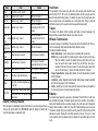 2
2
-
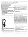 3
3
-
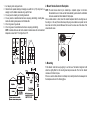 4
4
-
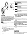 5
5
-
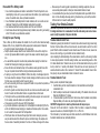 6
6
-
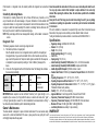 7
7
-
 8
8
-
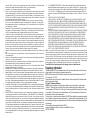 9
9
-
 10
10
-
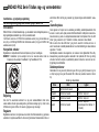 11
11
-
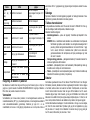 12
12
-
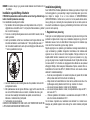 13
13
-
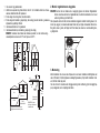 14
14
-
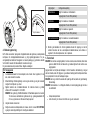 15
15
-
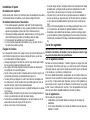 16
16
-
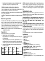 17
17
-
 18
18
-
 19
19
-
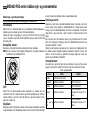 20
20
-
 21
21
-
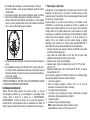 22
22
-
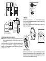 23
23
-
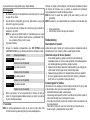 24
24
-
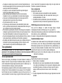 25
25
-
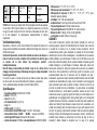 26
26
-
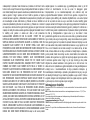 27
27
-
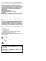 28
28
-
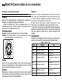 29
29
-
 30
30
-
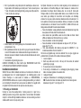 31
31
-
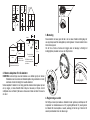 32
32
-
 33
33
-
 34
34
-
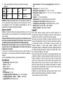 35
35
-
 36
36
-
 37
37
-
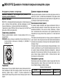 38
38
-
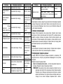 39
39
-
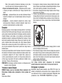 40
40
-
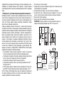 41
41
-
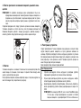 42
42
-
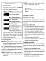 43
43
-
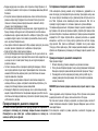 44
44
-
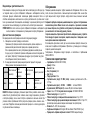 45
45
-
 46
46
-
 47
47
-
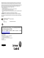 48
48


Tyco Visonic SMD-429 PG2 Series Installation And Operating Instructions Manual
- Typ
- Installation And Operating Instructions Manual
på andra språk
- English: Tyco Visonic SMD-429 PG2 Series
- dansk: Tyco Visonic SMD-429 PG2 Series
- русский: Tyco Visonic SMD-429 PG2 Series
Relaterade papper
Andra dokument
-
Abus FURM50000 Bruksanvisningar
-
Risco RWX34S Installation Instructions Manual
-
Abus RM 04 Li VdS Radio Datablad
-
DSC WS8985 Installation Instructions Manual
-
DEXAPLAN HA 621 - 10-2007 Safety Instructions
-
CARLO GAVAZZI BSG-SMO Installationsguide
-
Ebode ESD18 Användarmanual
-
-
-
Kidde SMOKE AND CARBON MONOXIDE ALARM Användarmanual