
AT-7000-EUR
Advanced Wire Tracers
AT-7020-EUR, AT-7030-EUR
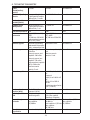
ItalianoEspañolFrançaisDeutschEnglish Czech Finnish
Portugués Russian Slovak SwedishDutch Norsk Polski
Languages available (please select):
User Manual


AT-7000-EUR
Advanced Wire Tracer
AT-7020-EUR
AT-7030-EUR
User Manual
03/2015, 4628886 Rev A
©2015 Beha-Amprobe.
All rights reserved.
English

Limited Warranty and Limitation of Liability
Your Amprobe product will be free from defects in material and workmanship for 1 year from
the date of purchase. This warranty does not cover fuses, disposable batteries or damage from
accident, neglect, misuse, alteration, contamination, or abnormal conditions of operation or
handling. Resellers are not authorized to extend any other warranty on Amprobe’s behalf.
To obtain service during the warranty period, return the product with proof of purchase to
an authorized Amprobe Test Tools Service Center or to an Amprobe dealer or distributor. See
Repair Section for details. THIS WARRANTY IS YOUR ONLY REMEDY. ALL OTHER WARRANTIES
- WHETHER EXPRESS, IMPLIED OR STAUTORY - INCLUDING IMPLIED WARRANTIES OF
FITNESS FOR A PARTICULAR PURPOSE OR MERCHANTABILITY, ARE HEREBY DISCLAIMED.
MANUFACTURER SHALL NOT BE LIABLE FOR ANY SPECIAL, INDIRECT, INCIDENTAL OR
CONSEQUENTIAL DAMAGES OR LOSSES, ARISING FROM ANY CAUSE OR THEORY. Since some
states or countries do not allow the exclusion or limitation of an implied warranty or of
incidental or consequential damages, this limitation of liability may not apply to you.
Repair
All Amprobe tools returned for warranty or non-warranty repair or for calibration should
be accompanied by the following: your name, company’s name, address, telephone number,
and proof of purchase. Additionally, please include a brief description of the problem or
the service requested and include the test leads with the meter. Non-warranty repair or
replacement charges should be remitted in the form of a check, a money order, credit card
with expiration date, or a purchase order made payable to Amprobe.
In-warranty Repairs and Replacement – All Countries
Please read the warranty statement and check your battery before requesting repair. During
the warranty period, any defective test tool can be returned to your Amprobe distributor for
an exchange for the same or like product. Please check the “Where to Buy” section on
www.Amprobe.com for a list of distributors near you. Additionally, in the United States and
Canada, in-warranty repair and replacement units can also be sent to an Amprobe Service
Center (see address below).
Non-warranty Repairs and Replacement – United States and Canada
Non-warranty repairs in the United States and Canada should be sent to an Amprobe Service
Center. Call Amprobe or inquire at your point of purchase for current repair and replacement
rates.
USA: Canada:
Amprobe Amprobe
Everett, WA 98203 Mississauga, ON L4Z 1X9
Tel: 888-993-5853 Tel: 905-890-7600
Fax: 425-446-6390 Fax: 905-890-6866
Non-warranty Repairs and Replacement – Europe
European non-warranty units can be replaced by your Amprobe distributor for a nominal
charge. Please check the “Where to Buy” section on www.Beha-Amprobe.com for a list of
distributors near you.
Amprobe Europe*
Beha-Amprobe
In den Engematten 14
79286 Glottertal, Germany
Tel.: +49 (0) 7684 8009 - 0
www.Amprobe.eu
*(Correspondence only – no repair or replacement available from this address. European
customers please contact your distributor.)

1
AT-7000-EUR Series
CONTENTS
1. PRECAUTIONS AND SAFETY MEASURES ............................................................. 2
2. KIT COMPONENTS ................................................................................................. 5
2.1 AT-7000-RE Receiver ......................................................................................................6
2.2 AT-7000-TE Transmitter .................................................................................................8
2.3 TL-7000-EUR Test Lead & Accessory Kit ........................................................................9
2.4 SC-7000-EUR Signal Clamp (AT-7030 Kit) .....................................................................10
2.5 BR-7000-T Signal Booster Rechargeable Battery Pack (AT-7030 Kit) .........................10
3. MAIN APPLICATIONS ............................................................................................ 11
3.1 Tracing Energized Wires
• SMART SENSOR .......................................................................................................... 12
3.2 Tracing Energized Wires
• TIP SENSOR Energized ................................................................................................ 14
3.3 Tracing De-Energized Wires
• TIP SENSOR De-Energized ..........................................................................................16
3.4 Identifying Breakers and Fuses
• BREAKER Energized (Energized Circuits) ..................................................................18
3.5 Identifying De-Energized Breakers and Fuses
• BREAKER De-Energized (De-Energized Circuits) ......................................................20
3.6 NCV Mode .......................................................................................................................21
4. SPECIAL APPLICATIONS ........................................................................................ 22
4.1 RCD-Protected Circuit Wire Tracing ..............................................................................22
4.2 Finding Breaks/Opens ................................................................................................... 22
4.3 Finding Shorts ...............................................................................................................23
4.4 Tracing Wires in Metal Conduit ...................................................................................24
4.5 Tracing Non-Metallic Pipes and Conduits ....................................................................24
4.6 Tracing Shielded Wires ..................................................................................................24
4.7 Tracing Underground Wires ..........................................................................................25
4.8 Tracing Low Voltage Wires and Data Cables ...............................................................25
4.9 Sorting Bundled Wires ..................................................................................................25
4.10 No Access to Bare Conductors (Signal Clamp) ...........................................................26
4.11 Locating Loads (Signal Clamp) .................................................................................... 27
4.12 Tracing breakers on systems with Light Dimmers ......................................................27
5. MAINTENANCE - BATTERY AND FUSE REPLACEMENT ........................................ 28
6. SPECIFICATIONS ..................................................................................................... 31

2
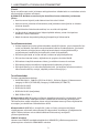
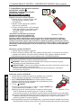
1. PRECAUTIONS AND SAFETY MEASURES
General
For your own safety and to avoid damage to the instrument we suggest you to follow the
procedures listed below:
NOTE: Before and during measurements be diligent to follow the instructions.
• Make sure that the electrical instrument is operating properly before use.
• Before attaching any of the conductors, make sure that the voltage present in the
conductor is in the range of the instrument.
• Keep the instruments in their carrying case when not in use.
• If the transmitter or receiver will not be used for a long time, remove the batteries to
prevent leakage in the instruments.
• Use Amprobe approved cables and accessories only.
Safety precautions
• In many instances, you will be working with dangerous level of voltage and/or current.
Therefore, it is important that you avoid direct contact with any uninsulated, voltage/
current carrying surfaces. Wear appropriate insulated gloves and protective clothing in
hazardous voltage areas where required.
• Do not measure voltage or current in wet or damp or dusty places
• Do not measure in presence of gas, explosive materials or combustibles
• Do not touch the circuit under test if no measurement is being taken
• Do not touch exposed metal parts, unused terminals, circuits and so on
• Do not use the instrument if it seems to be malfunctioning (i.e. if you notice
deformations, breaks, leakage of substances, and absence of messages on the display
and so on.)
Safety information
The product complies with:
• UL/IEC/EN 61010-1, CAN/CSA C22.2 No. 61010-1, Pollution Degree 2, Measurement
category IV 600 V (AT-7000-RE); Category IV 300V MAX (AT-7000-TE)
• IEC/EN 61010-2-033
• IEC/EN 61010-2-032
• IEC/EN 61010-031 (test leads)
• EMC IEC/EN 61326-1
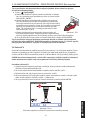
Measurement Category III (CAT III) is applicable to test and measuring circuits connected
to the distribution part of the building’s low-voltage MAINS installation. This part of the
installation is expected to have a minimum of two levels of over-current protective devices
between the transformer and possible connecting points
Measurement Category IV (CAT IV) is for circuits that are directly connected to the primary
utility power source for a given building or between the building power supply and the
main distribution board. Such equipment may include electricity tariff meters and primary
over current protection devices.
CENELEC Directives
The instruments conform to CENELEC Low-voltage directive 2006/95/EC and Electromagnetic
compatibility directive 2004/108/EC.

3
�Warnings: Read Before Using
To avoid possible electric shock or personal injury:
• Use the Meter only as specified in this manual or the protection provided by the
instrument might be impaired.
• Avoid working alone so assistance can be rendered.
• Do not use the Meter in wet or damp environments.
• Do not use the Meter if it appears damaged. Inspect the Meter before use. Look for cracks
or missing plastic. Pay particular attention to the insulation around the connectors.
• Inspect the test leads before use. Do not use them if insulation is damaged or metal is
exposed.
• Check the test leads for continuity. Replace damaged test leads before using the Meter.
• Have the Meter serviced only by qualified service personnel.
• Use extreme caution when working around bare conductors or bus bars. Contact with
the conductor could result in electric shock.
• Do not hold the Meter anywhere beyond the tactile barrier.
• Do not apply more than the rated voltage, as marked on the Meter, between the
terminals or between any terminal and earth ground.
• Remove test leads from the Meter before opening the Meter case or battery cover.
• Never operate the Meter with the battery cover removed or the case open.
• Never remove the battery cover or open the case of the Meter without first removing
the test leads from any circuit.
• Use caution when working with voltages above 30 V ac rms, 42 V ac peak, or 60 V dc.
These voltages pose a shock hazard.
• Do not attempt to measure any voltage that might exceed the maximum range of the Meter.
• Use the proper terminals, function, and range for your measurements.
• Do not operate the Meter around explosive gas, vapor, or dust.
• When using probes, keep fingers behind the finger guards.
• When making electrical connections, connect the common test lead before
connecting the live test lead; when disconnecting, disconnect the live test lead before
disconnecting the common test lead.
• To avoid false readings that can lead to electrical shock and injury, replace the battery
as soon as the low battery indicator appears.
• When servicing, use only specified user serviceable replacement parts.
• Adhere to local and national safety codes. Individual protective equipment must be used
to prevent shock and arc blast injury where hazardous live conductors are exposed.
• Only use the test lead provided with the Meter or Approved Probe Assembly rated CAT
IV 600V or better.
• Do not use HOT STICK to operate the AT-7000-RE Receiver around voltage more than 600V
• The transmitter voltage indication by LED or measurement on the LCD is not sufficient to
assure safety. Always verify the voltage presence/absence with approved voltage tester.
• The transmitter can generate dangerous voltages and currents at the output. Do not
touch exposed wires or circuitry while be tested to avoid electrical shock!
• In order to avoid electrical shock, the valid safety and national regulations regarding
excessive contact voltages must receive utmost attention when working with voltages
exceeding 120 V DC or 50 V RMS AC.
• Do not touch exposed circuitry or wires, metal probe tips or other metal parts of test
accessories. Always keep hands and fingers behind the probe or finger barriers.
• For products designed to be applied around or removed from uninsulated hazardous live
conductors, individual (personal) protective equipment must be used if hazardous live
parts of the installation could be accessible.
1. PRECAUTIONS AND SAFETY MEASURES

4
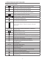
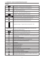
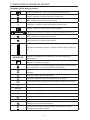
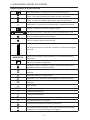
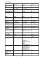
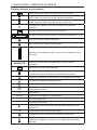
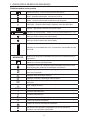
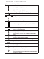
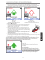
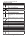
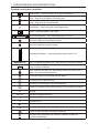
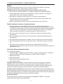
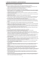
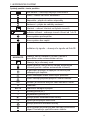
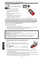
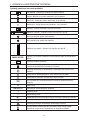
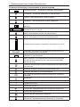
Symbols used in this product
Battery status – Displays the remaining battery charge
Home – Return to home screen when selected
Help – Enters to the help mode when selected
Settings – Enters to the settings menu when selected
Volume– Displays the volume in four levels
Sensitivity indicator – Displays the sensitivity level from 1 to 10.
Icon indicating energized system
Icon indicating de-energized system
99
SIGNAL
Signal strength indicator – Shows the strength of the signal
from 0 to 99
MAN/AUTO
Shows whether the sensitivity adjustment is in Manual or
Automatic mode
Indicates the volume is muted.
Lock indicates if the Auto sensitivity lock is active
(Only in Auto sensitivity mode)
Application and removal from hazardous live conductors permitted
Caution! Risk of electric shock.
�
Caution! Refer to the explanation in this Manual.
T
The equipment is protected by double insulation or
reinforced insulation.
J
Earth (Ground).
CAT IV
Overvoltage Category Rating
B
Alternating Current (AC).
F
Direct Current (DC).
)
Conforms to relevant North American Safety Standards.
P
Complies with European Directives.
Conforms to relevant Australian standards.
=
Do not dispose of this product as unsorted municipal waste. Contact
a qualified recycler.
1. PRECAUTIONS AND SAFETY MEASURES

5
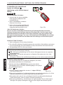
This manual contains information and warnings that must be followed for operating the
tester safely and maintaining the tester in a safe operating condition. If the tester is used in
a manner not specified by the manufacturer, the protection provided by the tester may be
impaired. This tester meets water and dust protection IP40 per IEC60529 Ed 2.1 (2001). Do
not use in rainfall! The tester is double insulated for protection per EN61010-1:2010 3rd Ed
to CAT IV 600V (AT-7000-RE) and CAT IV 300V (AT-7000-TE).
CAUTION: Do not connect the Transmitter to a separate ground in Electrically Susceptible
Patient areas of a health care facility. Make the ground connection first and disconnect it
last.
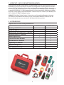
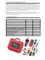
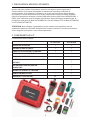
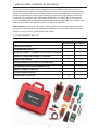
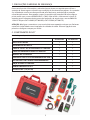
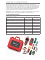
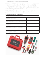
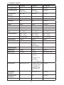
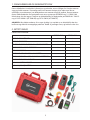
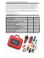
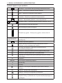
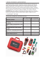
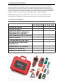
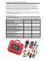
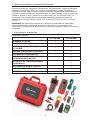
2. KIT COMPONENTS
Your shipping box should include:
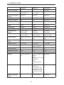
AT-7020-EUR AT-7030-EUR
AT-7000-RE RECEIVER 1 1
AT-7000-TE TRANSMITTER 1 1
TL-7000-EUR TEST LEAD AND ACCESSORY KIT 1 1
CC-7000-EUR HARD CARRYING CASE 1 1
USER MANUAL 1 1
BR-7000-T LI-ION RECHARGEABLE BATTERY - 1
BR-7000-EUR WITH 4AA RECHARGEABLE
BATTERIES
- 1
SC-7000-EUR SIGNAL CLAMP - 1
HS-1 MAGNETIC HANGER - 1
1.5 V AA (IEC R6) BATTERY 10 -
1. PRECAUTIONS AND SAFETY MEASURES

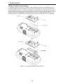
6
2. KIT COMPONENTS
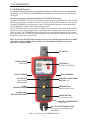
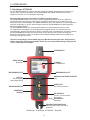
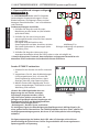
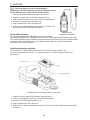
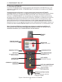
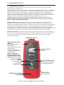
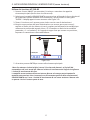
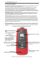
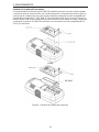
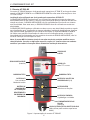
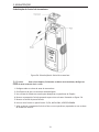
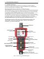
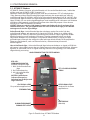
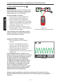
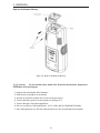
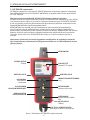
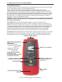
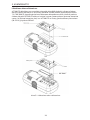
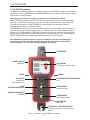
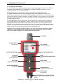
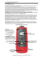
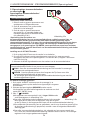
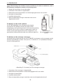
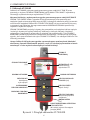
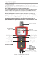
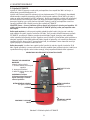
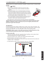
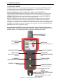
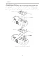
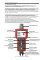
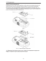
2.1 AT-7000-RE Receiver
The AT-7000-RE Receiver detects the signal generated by the AT-7000-TE transmitter along wires
using either the TIP SENSOR or SMART SENSOR and displays this information on the full color TFT
LCD display.
Active tracing using a signal generated by the AT-7000-TE Transmitter
The SMART SENSOR works with a 6 kHz signal generated along energized wires (above 30V
AC/DC) and provides an indication of the wire position and direction relative to the receiver.
The SMART SENSOR is not designed to work on de-energized systems; for that application
the TIP SENSOR should be used in de-energized mode.
The TIP SENSOR may be used on either energized or de-energized wires and can be used for
general tracing, tracing in tight spaces, locating breakers, pinpointing wires in bundles or in
junction boxes. The TIP SENSOR mode will pinpoint the wire location with both an audible
and visual indication of detected signal strength, but unlike SMART SENSOR mode it will not
provide wire direction or orientation.
Note: The receiver will NOT detect signals from the wire through metal conduit or shielded
cable. Refer to Special Applications, section 4.4 “Tracing Wires In Metal Conduit” for
alternative tracing methods.
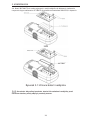
TIP SENSOR
LCD DISPLAY
Full color TFT display
TACTILE BARRIER
SENSITIVITY ADJUSTMENT
BUTTON (-/+)
SMART SENSOR
(Back side)
NCV BUTTON
Non-Contact
Voltage mode
TACTILE BARRIER
4-WAY
NAVIGATION KEYS
RUBBER OVER
MOLDED ENCLOSURE
ENTER BUTTON
Selects the functions
POWER BUTTON
Turns unit On / Off
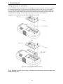
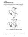
BATTERY COMPARTMENT
(Back side)
HOT STICK ATTACHMENT POINT
(Do not use for voltage higher
than 600V)
Figure 1: Overview of AT-7000-RE Receiver

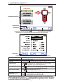
7
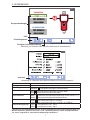
ENERGIZED:
DE-ENERGIZED:
--
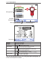
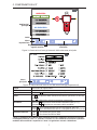
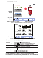
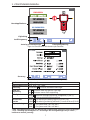
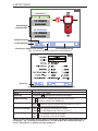
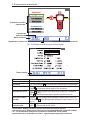
Main applications
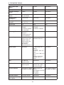
Setting menu
Help guide
Buzzer volume adjustment
Sensitivity adjustment
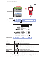
Figure 1a: Overview of all elements on home screen
Home menu
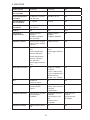
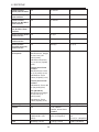
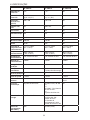
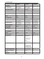
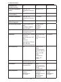
Figure 1b: Overview of all elements on the setting menu
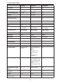
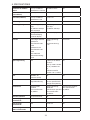
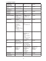
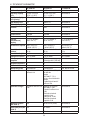
Language Select desired language
Backlight 25%, 50%, 75%, 100%
Setting
DEFAULT : Restore default settings
Help Guidance
ON : Device will guide you through each mode
OFF : Device will start without guidance
Sensitivity*
MAN : Manual sensitivity adjustment (+) and (-) keys
AUTO : Auto sensitivity adjustment
Smart Sensor Range
KURZ : Zur Leitererkennung bis 1 m (36 in)
LANG : Zur Leitererkennung von 1 m (36 in) – 6 m (240 in)
Breaker Voltage
120V : For 110V to 120V systems
230V : For 220V to 240V systems
*Note: The Auto and Manual sensitivity mode can be easily changed by pressing the + and
– key at the same time when the receiver is in a tracing mode. When sensitivity mode is set
to “Auto” manual adjustment is disabled.
2. KIT COMPONENTS

8
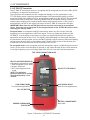
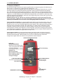
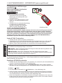
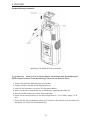
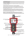
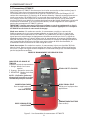
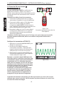
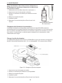
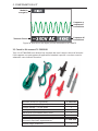
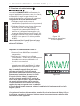
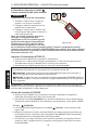
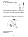
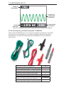
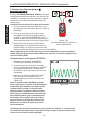
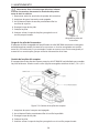
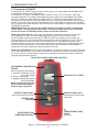
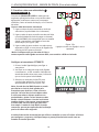
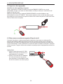
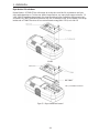
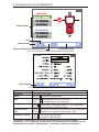
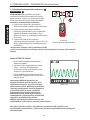
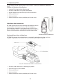
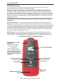
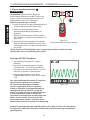
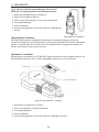
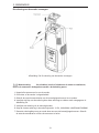
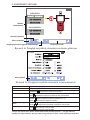
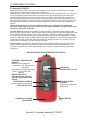
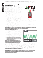
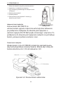
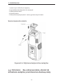
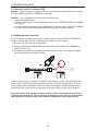
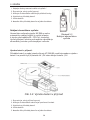
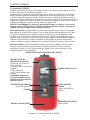
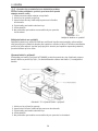
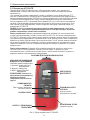
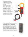
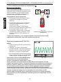
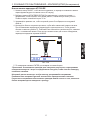
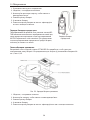
2.2 AT-7000-TE Transmitter
The AT-7000-TE Transmitter works on energized and de-energized circuits up to 300V AC/DC
in Category I-IV electrical environments.
The transmitter will measure the line voltage and display it on the transmitter’s color
TFT LCD display screen. Based on detected voltage it will automatically switch to either
energized mode (30 to 300V AC/DC) or de-energized mode (0 to 30V AC/DC). The energized
mode uses a lower transmission frequency (6kHz) than de-energized mode (33 kHz) to
reduce signal coupling with nearby metallic objects and improve results. If the circuit is
energized the red LED in the upper left corner of the AT-7000-TE transmitter will light.
IMPORTANT! Note that the red LED light will turn on when connected to an energized
circuit. Select the correct energized or de-energized mode on the AT-7000-RE receiver when
choosing your tracing mode.
Energized mode: In energized mode the transmitter draws very low current from the
energized circuit and generates a 6.25 kHz signal. This is very important feature of the
AT-7000-TE, since drawing current does not inject any signal that would harm sensitive
equipment connected to the circuit. The signal is also generated in a direct path between
the transmitter and the power source, thus NOT placing a signal onto any branches enabling
wiring tracing directly back to the breaker panel. Please note that due to this feature, the
transmitter has to be connected on the load side of the circuit.
De-energized mode: In de-energized mode the transmitter injects a 32.8 kHz signal onto the
circuit. In this mode, since the signal is injected, it will travel through all the circuit branches.
It is a high frequency, very low energy signal that will not harm any sensitive equipment
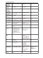
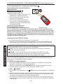
RED LED VOLTAGE INDICATOR
Indicates the transmitter mode
1. Red: Energized circuit mode
2. Amber: Overload
3. OFF: De-energized circuit
mode
NOTE: The indication
(presence/absence) of voltage
could be delayed by a few
seconds
LOW SIGNAL MODE
For precision applications
ON / OFF BUTTON
COLOR TFT LCD DISPLAY
TEST LEADS CONNECTION JACKS
HIGH SIGNAL MODE
Used for most applications
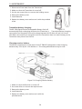
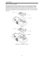
BATTERY COMPARTMENT
(Back side)
RUBBER OVERMOLDED
ENCLOSURE
Figure 2: Overview of AT-7000-TE Transmitter
2. KIT COMPONENTS

9
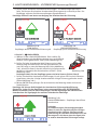
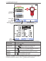
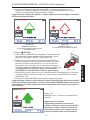
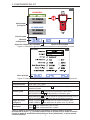
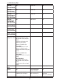
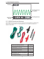
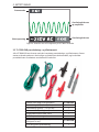
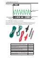
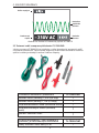
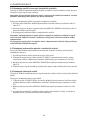
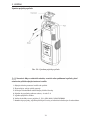
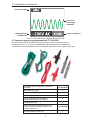
Power Mode
Detected Voltage
Transmission
Frequency &
Amplitude
Transmission
Frequency
Figure 2a: Overview of AT-7000-TE Transmitter LCD Screen
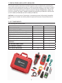
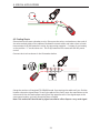
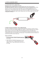
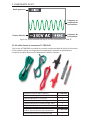
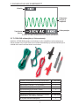
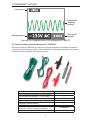
2.3 TL-7000-EUR Test Lead & Accessory Kit
All AT-7000-EUR kits come with our complete test leads & accessory kit. The kit supports a
wide range of standard and specialty applications and contains test leads and adaptors as
outlined below:
Accessories included with the product TL-7000-EUR
Test lead (red) 1.9m (6.4 ft.) 1
Test lead (green) 7.7 m (25 ft.) 1
Test probe set (red and black) 1
Alligator clip set (red, black) 1
Special test lead 1
Optional accessories - not inluded with the
product, need to be purchased seprately
TL-7000-25M
25m long green test lead 1
2. KIT COMPONENTS

10
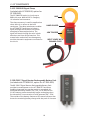
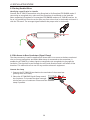
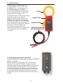
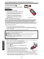
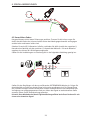
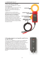
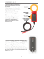
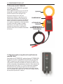
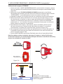
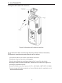
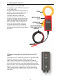
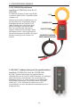
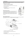
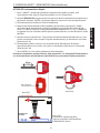
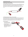
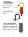
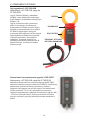
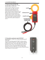
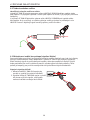
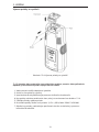
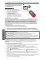
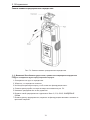
2.4 SC-7000-EUR Signal Clamp
(included with AT-7030-EUR, option for
AT-7020-EUR)
The SC-7000-EUR works in circuits up to
600V with max. 400A AC/DC in Category
I-IV electrical environments.
The clamp accessory is used for applications
when there is no access to the bare
conductors. The clamp attachment enables
the AT-7000-TE Transmitter to induce a
signal through the insulation into either
energized or de-energized wires. The
signal will travel through the wire in both
directions and into all the branches. This
transmission method will not damage any
sensitive electronic equipment connected to
the circuit.
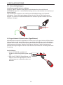
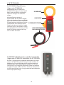
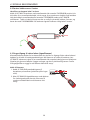
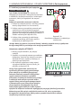
2.5 BR-7000-T Signal Booster Rechargeable Battery Pack
(included with AT-7030-EUR, option for AT-7020-EUR)
The BR-7000-T Signal Booster Rechargeable Battery Pack
provides increased power to the AT-7000-TE Transmitter,
enabling improved wire tracing results in energized, de-
energized and clamp modes. This 7.2V, 2.2 Ah Lithium-Ion
(Li-Ion) battery pack automatically begins recharging when
the transmitter is connected to circuits between 90V - 270V.
The outside of the battery features a LED status indicator that
shows the remaining battery charge with the push of a button.
JAW
HAND GUARD
JAW TRIGGER
INPUT LEADS WITH
BANANA PLUG
2. KIT COMPONENTS

11
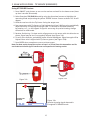
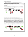
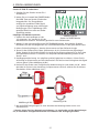
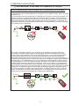
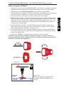
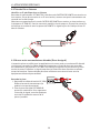
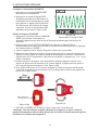
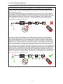
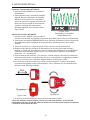
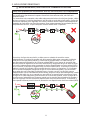
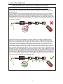
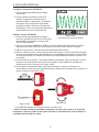
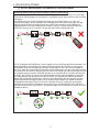
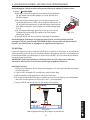
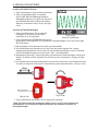
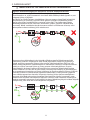
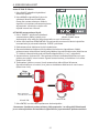
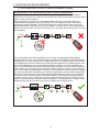
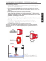
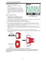
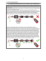
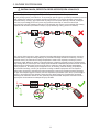
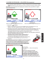
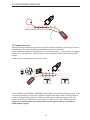
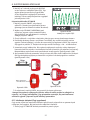
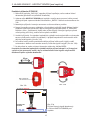
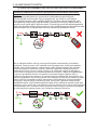
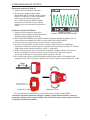
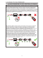
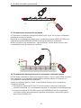
• �IMPORTANT NOTICE, PLEASE READ BEFORE YOU START TRACING
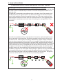
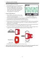
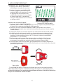
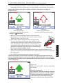
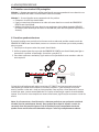
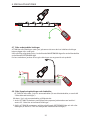
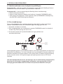
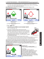
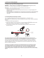
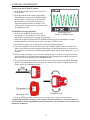
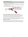
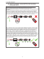
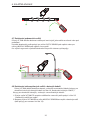
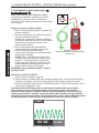
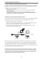
Avoiding signal cancellation problems with a separate ground connection
The signal generated by the transmitter creates an electromagnetic field around the wire.
This field is what is detectable by the receiver. The clearer this signal, the easier it is to
trace the wire.
If transmitter is connected to two adjacent wires on the same circuit (for example, Line
and Neutral wires), the signal travels in one directions through the first wire and then
returns (with opposite direction) through the second one. This causes creation of two
electromagnetic fields around each wire with opposite direction. These opposing fields
will partially or completely cancel each other out, making wire tracing difficult if not
impossible.
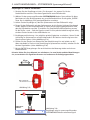
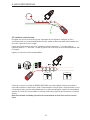
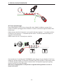
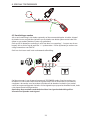
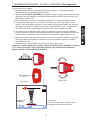
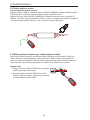
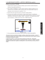
To avoid the cancellation effect, a separate Neutral connection method should be used.
The red test lead of the transmitter should be connected to the Line wire of the circuit
you wish to trace and the green test lead to a Neutral wire either directly at the RDC
or at the closest connection point to the RCD as it is possible. Please make sure that Line
wire and separate Neutral are connected to the same RCD, otherwise the RCD will trip.
Proper connection will be indicated by the red LED on a transmitter to light up. If the LED
is OFF, make sure the circuit is energized and the red test lead is connected to Line wire,
and green to the Neutral. The separate Neutral connection creates the maximum signal
strength, because the electromagnetic field created around the Live wire is not being
canceled by a signal on the return path flowing along an adjacent wire (Line and Neutral)
in the opposite direction, but rather through the separate Neutral circuit. Please note
that connecting a test lead to Ground instead of Neutral, will trip the RCD. The ground
connection can be used for circuits that are not protected by the RCD.
3. MAIN APPLICATIONS

12
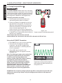
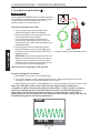
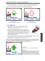
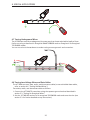
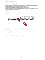
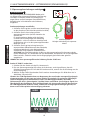
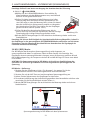
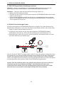
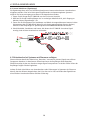
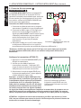
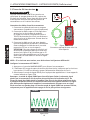
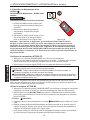
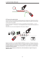
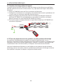
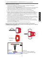
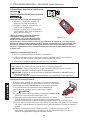
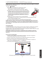
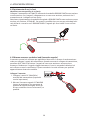
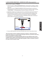
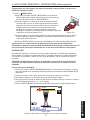
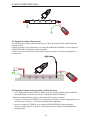
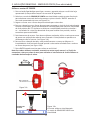
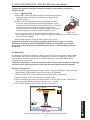
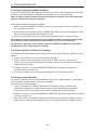
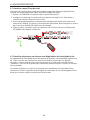
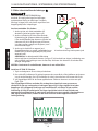
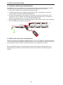
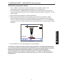
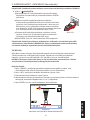
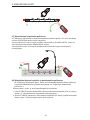
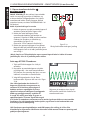
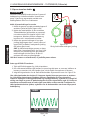
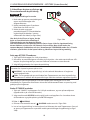
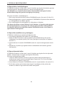
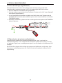
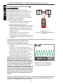
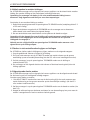
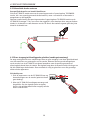
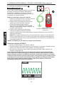
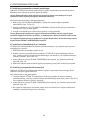
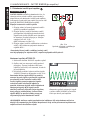
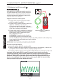
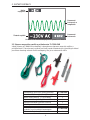
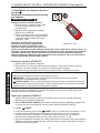
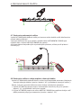
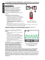
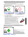
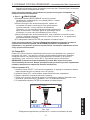
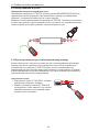
3.1 Tracing Energized Wires
SMART SENSOR
The SMART SENSOR enables easier wire tracing by
showing the direction and position of the wire and
is the recommended method for tracing energized
wires (does not work on de-energized circuits, use
de-energized TIP SENSOR for that application).
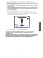
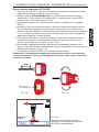
Connecting transmitter test leads
1. Connect green and red test leads to the
transmitter (polarity does not matter)
2. Connect red lead to energized Line wire (on
the load side of the system). The signal will
ONLY be transmitted between the outlet to
which the transmitter is connected and the
source of power (see Figure 3.1a).
(refer to section 2.2 for further explanation).
3. Connect green lead to a separate Neutral wire
at the RCD or at a connection point as close to
the RCD as it is possible.*
*Note: Please make sure that Line wire and
separate Neutral are connected to the same RCD, otherwise the RCD will trip.
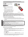
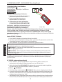
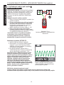
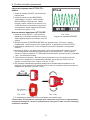
Set up the AT-7000-TE Transmitter:
1. Press ON/OFF key to turn on the transmitter.
2. Verify that the test leads are properly
connected - the red LED voltage status
indicator should be on, indicating that the
circuit is energized.
3. Select HIGH signal mode for most
applications. Screen will appear as shown
in Figure 3.1b.
Note: The LOW signal mode can be used to limit
the signal level generated by the transmitter
in order to more precisely pinpoint wire
location. A lower signal level reduces coupling
to neighboring wires and metal objects
and helps to avoid misreading due to ghost
signals. A lower signal also helps to prevent
oversaturating the receiver with a strong
signal that covers a large area. The LOW signal
mode function is rarely used, only for most
demanding precise wire tracing applications.
ATTENTION: The transmitter voltage indication by LED or measurement on the LCD is not
sufficient to assure safety. Always verify the voltage presence/absence with approved
voltage tester.
3. MAIN APPLICATIONS - SMART SENSOR (ENERGIZED)
Figure 3.1b
Transmitter screen showing signal in
HIGH mode with 6kHz frequency for
energized circuit
SMART SENSOR
Figure 3.1a
Proper connection with separate ground

13
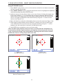
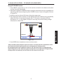
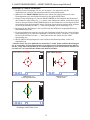
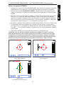
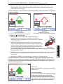
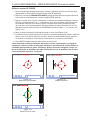
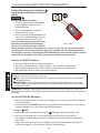
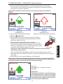
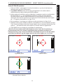
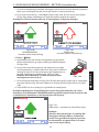
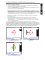
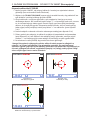
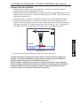
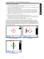
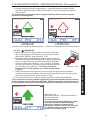
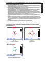
Using AT-7000-RE Receiver
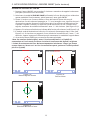
1. Press ‘ON/OFF’ push button to turn on the receiver and wait for the home screen (boot
up time is around 30 seconds).
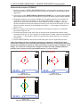
2. Select SMART SENSOR mode by using the directional arrows to highlight this operating
mode and pressing the yellow ENTER button.
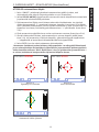
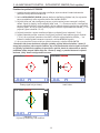
3. Hold the receiver with the Smart Sensor on the rear of the unit facing the target area.
If the screen flashes a “?” in a red target then no signal is detected. Move the Smart
Sensor closer to the target area until the signal is detected and you see a directional
arrow. If no signal is detected increase the sensitivity using the “+” button on the
receiver. (see Figure 3.1c)*
4. Move the Receiver in direction indicated by the arrow on the screen (see Figure 3.1d)
5. Green target symbol indicates that the Receiver is directly over the wire (see Figure
3.1e). If Receiver will not lock on the wire, decrease sensitivity using the “-“ on the
keypad or set the transmitter to transmit at LOW signal mode.
6. Press ENTER when complete to return to Home screen.
*Note: For best results, keep the receiver at least 1 m (3 feet) from the transmitter and
its test leads to minimize signal interference and improve wire tracing results. Select the
“Long” Smart Sensor Range in the Settings Menu if working with wires that are located
behind walls, floors or ceilings deeper than 1m (3 feet).
Figure 3.1c
No signal detected
Figure 3.1d
Wire on the left
Figure 3.1e
Receiver locked on wire
3. MAIN APPLICATIONS - SMART SENSOR (ENERGIZED)
SMART SENSOR

14
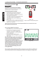
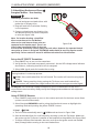
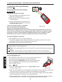
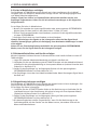
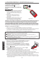
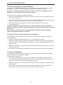
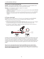
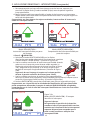
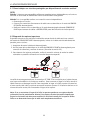
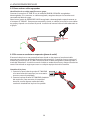
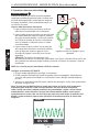
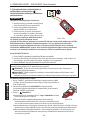
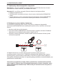
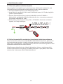
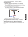
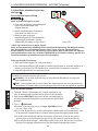
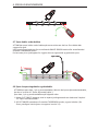
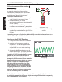
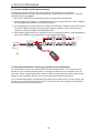
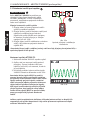
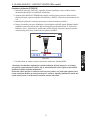
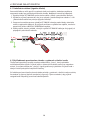
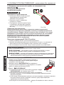
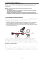
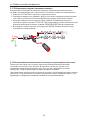
3.2 Tracing Energized Wires
TIP SENSOR
TIP SENSOR mode is used for the following
applications: pinpointing a wire in a bundle,
tracing in corners and confined spaces such as
junction boxes or inside enclosures.
Connecting transmitter test leads
1. Connect green and red test leads to the
transmitter (polarity does not matter)
2. Connect red lead to energized Line wire (on
the load side of the system).
The signal will ONLY be transmitted between
the outlet to which the transmitter is
connected and the source of power (see
Figure 3.2a).
3. Connect green lead to a separate Neutral wire
at the RCD or at a connection point as close to
the RCD as it is possible.
*Note: Please make sure that Line wire and separate Neutral are connected to the same
RCD, otherwise the RCD will trip.
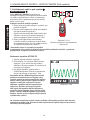
Set up the AT-7000-TE Transmitter:
1. Press ON/OFF key to turn on the transmitter.
2. Verify that the test leads are properly
connected - the red LED voltage status
indicator should be on, indicating that the
circuit is energized.
3. Select HIGH signal mode for most
applications. Screen will appear as shown in
Figure 3.2b.
Note: The LOW signal mode can be used to limit
the signal level generated by the transmitter in
order to more precisely pinpoint wire location.
A lower signal level reduces coupling to
neighboring wires and metal objects and helps to
avoid misreading due to ghost signals. A lower
signal also helps to prevent oversaturating the
receiver with a strong signal that covers a large
area. The LOW signal mode function is rarely
used, only for most demanding precise wire
tracing applications.
The transmitter voltage indication by LED or measurement on the LCD is not sufficient to
assure safety. Always verify the voltage presence/absence with approved voltage tester.
3. MAIN APPLICATIONS - TIP SENSOR (ENERGIZED)
TIP SENSOR
Figure 3.2a
Proper connection with separate ground
Figure 3.2b

15
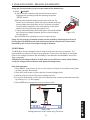
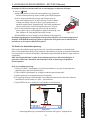
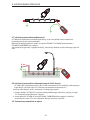
Using AT-7000-RE Receiver
1. Press ‘ON/OFF’ push button to turn on the receiver and wait for the home screen (boot
up time is around 30 seconds).
2. Select Energized TIP SENSOR mode by using the directional arrows to highlight this
operating mode and pressing the yellow “ENTER” button. Screen as shown in 3.2e will
appear.
3. Hold the receiver with the Tip Sensor facing the target area.
4. Scan target area with Tip Sensor to find highest signal level. While tracing, periodically
adjust sensitivity to keep signal strength near 75. Increase or decrease sensitivity
by pressing + or – on the keypad. If signal is too strong for precise locating, change
transmitter to LOW mode.
5. Receiver Positioning: For best results, align groove on tip sensor with wire direction as
shown. Signal may be lost if not properly aligned. (see Figure 3.2c)
6. To verify wire direction, periodically rotate receiver 90 degrees. Signal strength will be
highest when wire is aligned with Tip Sensor groove. (see Figure 3.2d)
7. Press ENTER when complete to return to Home screen.
Note: For best results, keep the receiver at least 1 m (3 feet) from the transmitter and its
test leads to minimize signal interference and improve wire tracing results.
Figure 3.2c
Figure 3.2d
Figure 3.2e
Receiver showing signal detected in
Energized TIP SENSOR mode
30-600V AC/DC
40-400 HZ
TIP SENSOR ENERGIZED
-
-
75
SIGNAL
3. MAIN APPLICATIONS - TIP SENSOR (ENERGIZED)
TIP SENSOR

16
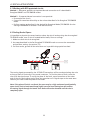
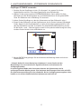
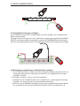
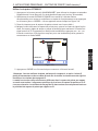
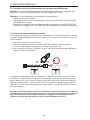
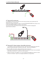
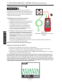
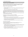
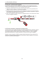
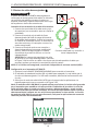
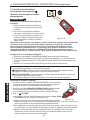
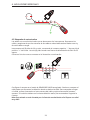
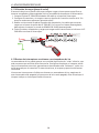
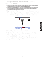
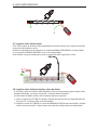
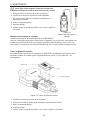
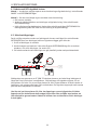
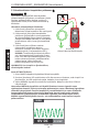
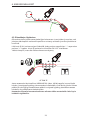
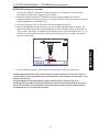
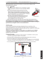
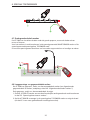
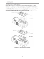
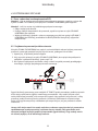
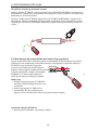
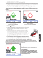
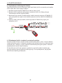
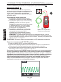
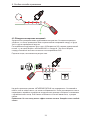
3.3 Tracing De-energized Wires
TIP SENSOR
De-energized TIP SENSOR mode is used for general
wire tracing, pinpointing wires in bundles, tracing
in tight corners and confined spaces such as
junction boxes or inside enclosures.
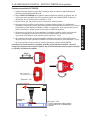
Connecting transmitter test leads
1. Connect green and red test leads to the
transmitter (polarity does not matter)
2. Connect red lead to de-energized Line wire
(on the load side of the system).
In de-energized mode the signal will be
injected to ALL branches of the circuit, not
just between the outlet and the breaker as in
energized modes.
3. Connect green lead to a separate ground
(metal building structure, metal water pipe,
or ground wire / Protective Ground (PE) on a
separate circuit).
ATTENTION: Due to safety reasons this is only
allowed in de-energized circuits. (see figure
3.3a) Do not use a ground wire that runs in
parallel to the wire you are going to trace, as
it will reduce or cancel tracing signal.
NOTE:If circuit is energized you will trip RCD.
Set up the AT-7000-TE Transmitter:
1. Press ON/OFF key to turn on the transmitter.
2. The red LED voltage status indicator should be off, indicating that the circuit is de-
energized. If LED is on, disconnect power to the circuit.
3. Select HIGH signal mode for most applications. Screen will appear as shown in Figure 3.3b
Note: The LOW signal mode can be used to limit the signal level generated by the
transmitter in order to more precisely pinpoint wire location. A lower signal level reduces
coupling to neighboring wires and metal objects and helps to avoid misreading due to
ghost signals. A lower signal also helps to prevent oversaturating the receiver with a
strong signal that covers a large area. The LOW signal mode function is rarely used, only for
most demanding precise wire tracing applications.
HIGH
0V DC
33 KHZ
Figure 3.3b
3. MAIN APPLICATIONS - TIP SENSOR (DE-ENERGIZED)
TIP SENSOR
Figure 3.3a
Proper connection with separate ground
Sidan laddas...
Sidan laddas...
Sidan laddas...
Sidan laddas...
Sidan laddas...
Sidan laddas...
Sidan laddas...
Sidan laddas...
Sidan laddas...
Sidan laddas...
Sidan laddas...
Sidan laddas...
Sidan laddas...
Sidan laddas...
Sidan laddas...
Sidan laddas...
Sidan laddas...
Sidan laddas...
Sidan laddas...
Sidan laddas...
Sidan laddas...
Sidan laddas...
Sidan laddas...
Sidan laddas...
Sidan laddas...
Sidan laddas...
Sidan laddas...
Sidan laddas...
Sidan laddas...
Sidan laddas...
Sidan laddas...
Sidan laddas...
Sidan laddas...
Sidan laddas...
Sidan laddas...
Sidan laddas...
Sidan laddas...
Sidan laddas...
Sidan laddas...
Sidan laddas...
Sidan laddas...
Sidan laddas...
Sidan laddas...
Sidan laddas...
Sidan laddas...
Sidan laddas...
Sidan laddas...
Sidan laddas...
Sidan laddas...
Sidan laddas...
Sidan laddas...
Sidan laddas...
Sidan laddas...
Sidan laddas...
Sidan laddas...
Sidan laddas...
Sidan laddas...
Sidan laddas...
Sidan laddas...
Sidan laddas...
Sidan laddas...
Sidan laddas...
Sidan laddas...
Sidan laddas...
Sidan laddas...
Sidan laddas...
Sidan laddas...
Sidan laddas...
Sidan laddas...
Sidan laddas...
Sidan laddas...
Sidan laddas...
Sidan laddas...
Sidan laddas...
Sidan laddas...
Sidan laddas...
Sidan laddas...
Sidan laddas...
Sidan laddas...
Sidan laddas...
Sidan laddas...
Sidan laddas...
Sidan laddas...
Sidan laddas...
Sidan laddas...
Sidan laddas...
Sidan laddas...
Sidan laddas...
Sidan laddas...
Sidan laddas...
Sidan laddas...
Sidan laddas...
Sidan laddas...
Sidan laddas...
Sidan laddas...
Sidan laddas...
Sidan laddas...
Sidan laddas...
Sidan laddas...
Sidan laddas...
Sidan laddas...
Sidan laddas...
Sidan laddas...
Sidan laddas...
Sidan laddas...
Sidan laddas...
Sidan laddas...
Sidan laddas...
Sidan laddas...
Sidan laddas...
Sidan laddas...
Sidan laddas...
Sidan laddas...
Sidan laddas...
Sidan laddas...
Sidan laddas...
Sidan laddas...
Sidan laddas...
Sidan laddas...
Sidan laddas...
Sidan laddas...
Sidan laddas...
Sidan laddas...
Sidan laddas...
Sidan laddas...
Sidan laddas...
Sidan laddas...
Sidan laddas...
Sidan laddas...
Sidan laddas...
Sidan laddas...
Sidan laddas...
Sidan laddas...
Sidan laddas...
Sidan laddas...
Sidan laddas...
Sidan laddas...
Sidan laddas...
Sidan laddas...
Sidan laddas...
Sidan laddas...
Sidan laddas...
Sidan laddas...
Sidan laddas...
Sidan laddas...
Sidan laddas...
Sidan laddas...
Sidan laddas...
Sidan laddas...
Sidan laddas...
Sidan laddas...
Sidan laddas...
Sidan laddas...
Sidan laddas...
Sidan laddas...
Sidan laddas...
Sidan laddas...
Sidan laddas...
Sidan laddas...
Sidan laddas...
Sidan laddas...
Sidan laddas...
Sidan laddas...
Sidan laddas...
Sidan laddas...
Sidan laddas...
Sidan laddas...
Sidan laddas...
Sidan laddas...
Sidan laddas...
Sidan laddas...
Sidan laddas...
Sidan laddas...
Sidan laddas...
Sidan laddas...
Sidan laddas...
Sidan laddas...
Sidan laddas...
Sidan laddas...
Sidan laddas...
Sidan laddas...
Sidan laddas...
Sidan laddas...
Sidan laddas...
Sidan laddas...
Sidan laddas...
Sidan laddas...
Sidan laddas...
Sidan laddas...
Sidan laddas...
Sidan laddas...
Sidan laddas...
Sidan laddas...
Sidan laddas...
Sidan laddas...
Sidan laddas...
Sidan laddas...
Sidan laddas...
Sidan laddas...
Sidan laddas...
Sidan laddas...
Sidan laddas...
Sidan laddas...
Sidan laddas...
Sidan laddas...
Sidan laddas...
Sidan laddas...
Sidan laddas...
Sidan laddas...
Sidan laddas...
Sidan laddas...
Sidan laddas...
Sidan laddas...
Sidan laddas...
Sidan laddas...
Sidan laddas...
Sidan laddas...
Sidan laddas...
Sidan laddas...
Sidan laddas...
Sidan laddas...
Sidan laddas...
Sidan laddas...
Sidan laddas...
Sidan laddas...
Sidan laddas...
Sidan laddas...
Sidan laddas...
Sidan laddas...
Sidan laddas...
Sidan laddas...
Sidan laddas...
Sidan laddas...
Sidan laddas...
Sidan laddas...
Sidan laddas...
Sidan laddas...
Sidan laddas...
Sidan laddas...
Sidan laddas...
Sidan laddas...
Sidan laddas...
Sidan laddas...
Sidan laddas...
Sidan laddas...
Sidan laddas...
Sidan laddas...
Sidan laddas...
Sidan laddas...
Sidan laddas...
Sidan laddas...
Sidan laddas...
Sidan laddas...
Sidan laddas...
Sidan laddas...
Sidan laddas...
Sidan laddas...
Sidan laddas...
Sidan laddas...
Sidan laddas...
Sidan laddas...
Sidan laddas...
Sidan laddas...
Sidan laddas...
Sidan laddas...
Sidan laddas...
Sidan laddas...
Sidan laddas...
Sidan laddas...
Sidan laddas...
Sidan laddas...
Sidan laddas...
Sidan laddas...
Sidan laddas...
Sidan laddas...
Sidan laddas...
Sidan laddas...
Sidan laddas...
Sidan laddas...
Sidan laddas...
Sidan laddas...
Sidan laddas...
Sidan laddas...
Sidan laddas...
Sidan laddas...
Sidan laddas...
Sidan laddas...
Sidan laddas...
Sidan laddas...
Sidan laddas...
Sidan laddas...
Sidan laddas...
Sidan laddas...
Sidan laddas...
Sidan laddas...
Sidan laddas...
Sidan laddas...
Sidan laddas...
Sidan laddas...
Sidan laddas...
Sidan laddas...
Sidan laddas...
Sidan laddas...
Sidan laddas...
Sidan laddas...
Sidan laddas...
Sidan laddas...
Sidan laddas...
Sidan laddas...
Sidan laddas...
Sidan laddas...
Sidan laddas...
Sidan laddas...
Sidan laddas...
Sidan laddas...
Sidan laddas...
Sidan laddas...
Sidan laddas...
Sidan laddas...
Sidan laddas...
Sidan laddas...
Sidan laddas...
Sidan laddas...
Sidan laddas...
Sidan laddas...
Sidan laddas...
Sidan laddas...
Sidan laddas...
Sidan laddas...
Sidan laddas...
Sidan laddas...
Sidan laddas...
Sidan laddas...
Sidan laddas...
Sidan laddas...
Sidan laddas...
Sidan laddas...
Sidan laddas...
Sidan laddas...
Sidan laddas...
Sidan laddas...
Sidan laddas...
Sidan laddas...
Sidan laddas...
Sidan laddas...
Sidan laddas...
Sidan laddas...
Sidan laddas...
Sidan laddas...
Sidan laddas...
Sidan laddas...
Sidan laddas...
Sidan laddas...
Sidan laddas...
Sidan laddas...
Sidan laddas...
Sidan laddas...
Sidan laddas...
Sidan laddas...
Sidan laddas...
Sidan laddas...
Sidan laddas...
Sidan laddas...
Sidan laddas...
Sidan laddas...
Sidan laddas...
Sidan laddas...
Sidan laddas...
Sidan laddas...
Sidan laddas...
Sidan laddas...
Sidan laddas...
Sidan laddas...
Sidan laddas...
Sidan laddas...
Sidan laddas...
Sidan laddas...
Sidan laddas...
Sidan laddas...
Sidan laddas...
Sidan laddas...
Sidan laddas...
Sidan laddas...
Sidan laddas...
Sidan laddas...
Sidan laddas...
Sidan laddas...
Sidan laddas...
Sidan laddas...
Sidan laddas...
Sidan laddas...
Sidan laddas...
Sidan laddas...
Sidan laddas...
Sidan laddas...
Sidan laddas...
Sidan laddas...
Sidan laddas...
Sidan laddas...
Sidan laddas...
Sidan laddas...
Sidan laddas...
Sidan laddas...
Sidan laddas...
Sidan laddas...
Sidan laddas...
Sidan laddas...
Sidan laddas...
Sidan laddas...
Sidan laddas...
Sidan laddas...
Sidan laddas...
Sidan laddas...
Sidan laddas...
Sidan laddas...
Sidan laddas...
Sidan laddas...
Sidan laddas...
Sidan laddas...
Sidan laddas...
Sidan laddas...
Sidan laddas...
Sidan laddas...
Sidan laddas...
Sidan laddas...
Sidan laddas...
Sidan laddas...
Sidan laddas...
Sidan laddas...
Sidan laddas...
Sidan laddas...
Sidan laddas...
Sidan laddas...
Sidan laddas...
Sidan laddas...
Sidan laddas...
Sidan laddas...
Sidan laddas...
Sidan laddas...
Sidan laddas...
Sidan laddas...
Sidan laddas...
Sidan laddas...
Sidan laddas...
Sidan laddas...
Sidan laddas...
Sidan laddas...
Sidan laddas...
Sidan laddas...
Sidan laddas...
Sidan laddas...
Sidan laddas...
Sidan laddas...
Sidan laddas...
Sidan laddas...
Sidan laddas...
Sidan laddas...
Sidan laddas...
Sidan laddas...
Sidan laddas...
Sidan laddas...
Sidan laddas...
Sidan laddas...
Sidan laddas...
Sidan laddas...
Sidan laddas...
Sidan laddas...
Sidan laddas...
Sidan laddas...
Sidan laddas...
Sidan laddas...
Sidan laddas...
Sidan laddas...
Sidan laddas...
Sidan laddas...
Sidan laddas...
Sidan laddas...
Sidan laddas...
Sidan laddas...
Sidan laddas...
Sidan laddas...
Sidan laddas...
Sidan laddas...
Sidan laddas...
Sidan laddas...
Sidan laddas...
Sidan laddas...
Sidan laddas...
-
 1
1
-
 2
2
-
 3
3
-
 4
4
-
 5
5
-
 6
6
-
 7
7
-
 8
8
-
 9
9
-
 10
10
-
 11
11
-
 12
12
-
 13
13
-
 14
14
-
 15
15
-
 16
16
-
 17
17
-
 18
18
-
 19
19
-
 20
20
-
 21
21
-
 22
22
-
 23
23
-
 24
24
-
 25
25
-
 26
26
-
 27
27
-
 28
28
-
 29
29
-
 30
30
-
 31
31
-
 32
32
-
 33
33
-
 34
34
-
 35
35
-
 36
36
-
 37
37
-
 38
38
-
 39
39
-
 40
40
-
 41
41
-
 42
42
-
 43
43
-
 44
44
-
 45
45
-
 46
46
-
 47
47
-
 48
48
-
 49
49
-
 50
50
-
 51
51
-
 52
52
-
 53
53
-
 54
54
-
 55
55
-
 56
56
-
 57
57
-
 58
58
-
 59
59
-
 60
60
-
 61
61
-
 62
62
-
 63
63
-
 64
64
-
 65
65
-
 66
66
-
 67
67
-
 68
68
-
 69
69
-
 70
70
-
 71
71
-
 72
72
-
 73
73
-
 74
74
-
 75
75
-
 76
76
-
 77
77
-
 78
78
-
 79
79
-
 80
80
-
 81
81
-
 82
82
-
 83
83
-
 84
84
-
 85
85
-
 86
86
-
 87
87
-
 88
88
-
 89
89
-
 90
90
-
 91
91
-
 92
92
-
 93
93
-
 94
94
-
 95
95
-
 96
96
-
 97
97
-
 98
98
-
 99
99
-
 100
100
-
 101
101
-
 102
102
-
 103
103
-
 104
104
-
 105
105
-
 106
106
-
 107
107
-
 108
108
-
 109
109
-
 110
110
-
 111
111
-
 112
112
-
 113
113
-
 114
114
-
 115
115
-
 116
116
-
 117
117
-
 118
118
-
 119
119
-
 120
120
-
 121
121
-
 122
122
-
 123
123
-
 124
124
-
 125
125
-
 126
126
-
 127
127
-
 128
128
-
 129
129
-
 130
130
-
 131
131
-
 132
132
-
 133
133
-
 134
134
-
 135
135
-
 136
136
-
 137
137
-
 138
138
-
 139
139
-
 140
140
-
 141
141
-
 142
142
-
 143
143
-
 144
144
-
 145
145
-
 146
146
-
 147
147
-
 148
148
-
 149
149
-
 150
150
-
 151
151
-
 152
152
-
 153
153
-
 154
154
-
 155
155
-
 156
156
-
 157
157
-
 158
158
-
 159
159
-
 160
160
-
 161
161
-
 162
162
-
 163
163
-
 164
164
-
 165
165
-
 166
166
-
 167
167
-
 168
168
-
 169
169
-
 170
170
-
 171
171
-
 172
172
-
 173
173
-
 174
174
-
 175
175
-
 176
176
-
 177
177
-
 178
178
-
 179
179
-
 180
180
-
 181
181
-
 182
182
-
 183
183
-
 184
184
-
 185
185
-
 186
186
-
 187
187
-
 188
188
-
 189
189
-
 190
190
-
 191
191
-
 192
192
-
 193
193
-
 194
194
-
 195
195
-
 196
196
-
 197
197
-
 198
198
-
 199
199
-
 200
200
-
 201
201
-
 202
202
-
 203
203
-
 204
204
-
 205
205
-
 206
206
-
 207
207
-
 208
208
-
 209
209
-
 210
210
-
 211
211
-
 212
212
-
 213
213
-
 214
214
-
 215
215
-
 216
216
-
 217
217
-
 218
218
-
 219
219
-
 220
220
-
 221
221
-
 222
222
-
 223
223
-
 224
224
-
 225
225
-
 226
226
-
 227
227
-
 228
228
-
 229
229
-
 230
230
-
 231
231
-
 232
232
-
 233
233
-
 234
234
-
 235
235
-
 236
236
-
 237
237
-
 238
238
-
 239
239
-
 240
240
-
 241
241
-
 242
242
-
 243
243
-
 244
244
-
 245
245
-
 246
246
-
 247
247
-
 248
248
-
 249
249
-
 250
250
-
 251
251
-
 252
252
-
 253
253
-
 254
254
-
 255
255
-
 256
256
-
 257
257
-
 258
258
-
 259
259
-
 260
260
-
 261
261
-
 262
262
-
 263
263
-
 264
264
-
 265
265
-
 266
266
-
 267
267
-
 268
268
-
 269
269
-
 270
270
-
 271
271
-
 272
272
-
 273
273
-
 274
274
-
 275
275
-
 276
276
-
 277
277
-
 278
278
-
 279
279
-
 280
280
-
 281
281
-
 282
282
-
 283
283
-
 284
284
-
 285
285
-
 286
286
-
 287
287
-
 288
288
-
 289
289
-
 290
290
-
 291
291
-
 292
292
-
 293
293
-
 294
294
-
 295
295
-
 296
296
-
 297
297
-
 298
298
-
 299
299
-
 300
300
-
 301
301
-
 302
302
-
 303
303
-
 304
304
-
 305
305
-
 306
306
-
 307
307
-
 308
308
-
 309
309
-
 310
310
-
 311
311
-
 312
312
-
 313
313
-
 314
314
-
 315
315
-
 316
316
-
 317
317
-
 318
318
-
 319
319
-
 320
320
-
 321
321
-
 322
322
-
 323
323
-
 324
324
-
 325
325
-
 326
326
-
 327
327
-
 328
328
-
 329
329
-
 330
330
-
 331
331
-
 332
332
-
 333
333
-
 334
334
-
 335
335
-
 336
336
-
 337
337
-
 338
338
-
 339
339
-
 340
340
-
 341
341
-
 342
342
-
 343
343
-
 344
344
-
 345
345
-
 346
346
-
 347
347
-
 348
348
-
 349
349
-
 350
350
-
 351
351
-
 352
352
-
 353
353
-
 354
354
-
 355
355
-
 356
356
-
 357
357
-
 358
358
-
 359
359
-
 360
360
-
 361
361
-
 362
362
-
 363
363
-
 364
364
-
 365
365
-
 366
366
-
 367
367
-
 368
368
-
 369
369
-
 370
370
-
 371
371
-
 372
372
-
 373
373
-
 374
374
-
 375
375
-
 376
376
-
 377
377
-
 378
378
-
 379
379
-
 380
380
-
 381
381
-
 382
382
-
 383
383
-
 384
384
-
 385
385
-
 386
386
-
 387
387
-
 388
388
-
 389
389
-
 390
390
-
 391
391
-
 392
392
-
 393
393
-
 394
394
-
 395
395
-
 396
396
-
 397
397
-
 398
398
-
 399
399
-
 400
400
-
 401
401
-
 402
402
-
 403
403
-
 404
404
-
 405
405
-
 406
406
-
 407
407
-
 408
408
-
 409
409
-
 410
410
-
 411
411
-
 412
412
-
 413
413
-
 414
414
-
 415
415
-
 416
416
-
 417
417
-
 418
418
-
 419
419
-
 420
420
-
 421
421
-
 422
422
-
 423
423
-
 424
424
-
 425
425
-
 426
426
-
 427
427
-
 428
428
-
 429
429
-
 430
430
-
 431
431
-
 432
432
-
 433
433
-
 434
434
-
 435
435
-
 436
436
-
 437
437
-
 438
438
-
 439
439
-
 440
440
-
 441
441
-
 442
442
-
 443
443
-
 444
444
-
 445
445
-
 446
446
-
 447
447
-
 448
448
-
 449
449
-
 450
450
-
 451
451
-
 452
452
-
 453
453
-
 454
454
-
 455
455
-
 456
456
-
 457
457
-
 458
458
-
 459
459
-
 460
460
-
 461
461
-
 462
462
-
 463
463
-
 464
464
-
 465
465
-
 466
466
-
 467
467
-
 468
468
-
 469
469
-
 470
470
-
 471
471
-
 472
472
-
 473
473
-
 474
474
-
 475
475
-
 476
476
-
 477
477
-
 478
478
-
 479
479
-
 480
480
-
 481
481
-
 482
482
-
 483
483
-
 484
484
-
 485
485
-
 486
486
-
 487
487
-
 488
488
-
 489
489
-
 490
490
-
 491
491
-
 492
492
-
 493
493
-
 494
494
-
 495
495
-
 496
496
-
 497
497
-
 498
498
-
 499
499
-
 500
500
-
 501
501
-
 502
502
-
 503
503
-
 504
504
-
 505
505
-
 506
506
-
 507
507
-
 508
508


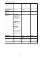
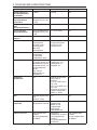
Beha-Amprobe AT-7000-EUR Användarmanual
- Typ
- Användarmanual
- Denna manual är också lämplig för
på andra språk
- italiano: Beha-Amprobe AT-7000-EUR Manuale utente
- čeština: Beha-Amprobe AT-7000-EUR Uživatelský manuál
- slovenčina: Beha-Amprobe AT-7000-EUR Používateľská príručka
- español: Beha-Amprobe AT-7000-EUR Manual de usuario
- Deutsch: Beha-Amprobe AT-7000-EUR Benutzerhandbuch
- polski: Beha-Amprobe AT-7000-EUR Instrukcja obsługi
- português: Beha-Amprobe AT-7000-EUR Manual do usuário
- français: Beha-Amprobe AT-7000-EUR Manuel utilisateur
- English: Beha-Amprobe AT-7000-EUR User manual
- русский: Beha-Amprobe AT-7000-EUR Руководство пользователя
- suomi: Beha-Amprobe AT-7000-EUR Ohjekirja
- Nederlands: Beha-Amprobe AT-7000-EUR Handleiding
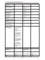
Andra dokument
-
Amprobe AC50A Leakage Clamp Meter Användarmanual
-
Smartwares® SH4-90158 Bruksanvisningar
-
-
TESTBOY 26 Användarmanual
-
Laserliner CableTracer Pro Bruksanvisning
-
-
-
-
Eden MA40 Bruksanvisning
-