
Installation Manual English
Installationsmanual Svensk
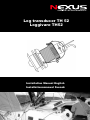
Log transducer TH 52
Loggivare TH52

LOG TH52 English
10-1

English LOG TH52
10-2

LOG TH52 English
10-3
Mounting instruction log/temp transducer
1 General ................................................................................................................... 3
1.1 Applications .................................................................................................... 3
1.2 Tools and Materials ........................................................................................ 4
1.3 Pre-Installation Test ........................................................................................ 4
1.4 Antifouling Paint .............................................................................................. 4
1.5 Mounting Location .......................................................................................... 4
2 Installation.............................................................................................................. 6
2.1 Bedding ........................................................................................................... 6
2.2 Installing .......................................................................................................... 6
2.3 Checking for Leaks ......................................................................................... 8
2.4 Installation in a Cored Fiberglass Hull............................................................. 8
3 Operation, Maintenance ...................................................................................... 10
3.1 How the Valve Works.................................................................................... 10
3.2 Using the Long Blanking Plug ....................................................................... 10
3.3 Servicing the Paddlewheel Insert .................................................................. 10
3.4 Servicing the Valve Assembly ....................................................................... 11
4 CONNECTION TO INSTRUMENT/CONTACTS ................................................... 13
5 CALIBRATION ...................................................................................................... 13
6 TECHNICAL DATA ............................................................................................... 13
1 General
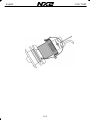
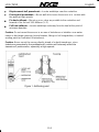
The log/temp transducer with Valve is an impeller transducer installed through the hull
and designed to meet the requirements of owners of sailing crafts and power boats.
CAUTION: NEVER USE SOLVENTS
Cleaners, fuel, paint, sealants, and other products may contain strong solvents, such as
acetone, which attack many plastics greatly reducing their strength.
1.1 Applications
Plastic housing recommended for fiberglass or metal hulls only. Never install a
plastic housing in a wood hull since swelling of the wood may overstress the plastic
causing a fracture.
Bronze housing recommended for fiberglass or wood hulls only. Never mount a
bronze housing in a metal hull because electrolytic corrosion will occur.
Stainless steel housing recommended for metal hulls to prevent electrolytic
corrosion.
IMPORTANT: Please read these instructions completely before proceeding with
the installation. These instructions supersede any other instructions in your
instrument manual if they differ.

English LOG TH52
10-4
1.2 Tools and Materials
Water-based or mineral spirits based antifouling paint (mandatory in salt water)
Safety goggles
Dust mask
Electric drill with 10mm (3/8") or larger chuck capacity
Drill bit 3mm or 1/8"
Hole saw 51mm or 2" (plastic or bronze housing)
57mm or 2-1/4" (stainless steel housing in a metal hull)
Countersink tool (installing a flush housing)
Sandpaper
Mild household detergent or weak solvent (such as alcohol)
File (installation in a metal hull)
Marine sealant
Additional washer [for aluminum hull less than 6mm (1/4") thick]
Zip-ties
Installation in a cored fiberglass hull (see page 3)
Hole saw for hull interior 60mm or 2-3/8"
Fiberglass cloth and resin or Cylinder, wax, tape, and casting epoxy
1.3 Pre-Installation Test
Connect the sensor to the instrument and spin the paddlewheel. Check for a speed
reading (and the approximate air temperature if applicable). If there is no reading or it is
inaccurate, return the instrument to the place of purchase.
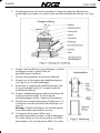
1.4 Antifouling Paint
Marine growth can accumulate rapidly on the sensor’s surface reducing performance
within weeks. Surfaces exposed to salt water must be coated with antifouling paint. Use
water-based or mineral spirits based antifouling paint only. Never use ketone based
paint, since ketones can attack many plastics possibly damaging the sensor. It is
easiest to apply antifouling paint before installing the sensor, but allow sufficient drying
time. Reapply paint every 6 months or at the beginning of each boating season. Paint
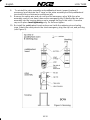
the following surfaces (see Figure 1):
Outside wall of the paddlewheel insert below the lower O-ring
Paddlewheel cavity
Paddlewheel
Exterior lip of the housing and valve assembly
Bore of the valve assembly up 30mm (1-1/4")
Blanking plug below the lower O-ring including the exposed end
1.5 Mounting Location
Turbulence-free water must flow over the paddlewheel at all speeds. Choose an
accessible spot inside the vessel. Allow a minimum of 280mm (11") of headroom for
the height of the housing, tightening the nuts, and removing the insert.

LOG TH52 English
10-5
Displacement hull powerboats—Locate amidships near the centerline.
Planing hull powerboats—Mount well aft to insure the sensor is in contact with
the water at high speeds.
Fin keel sailboats—Mount on or as close as possible to the centerline and
forward of the fin keel 300–600mm (1–2').
Full keel sailboats—Locate amidships and away from the keel at the point of
minimum deadrise.
Caution: Do not mount the sensor in an area of turbulence or bubbles: near water
intake or discharge openings; behind strakes, fittings or hull irregularities; or behind
eroding paint (an indication of turbulence).
Caution: Never mount the sensor directly ahead of a depth transducer, since
turbulence generated by the paddlewheel’s rotation will adversely affect the
transducer’s performance, especially at high speeds.

English LOG TH52
10-6
2 Installation
Cored fiberglass hull—Follow separate instructions on page 3.
Hole Drilling
Warning: Always wear safety goggles and a dust mask.
1. Drill a 3 mm or 1/8" pilot hole from inside the hull. If there is a rib, strut or other hull
irregularity near the selected mounting location, drill from the outside.
2. Using the appropriate size hole saw, cut the hole from outside the hull. Flush
housing—Use a countersink tool to create a ―seat‖ in the hull.
3. Sand and clean the area around the hole, inside and outside, to ensure that the
sealant will adhere properly to the hull. If there is any petroleum residue inside the
hull, remove it with either mild household detergent or a weak solvent (alcohol)
before sanding.
Metal hull—Remove all burrs with a file and sandpaper.
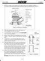
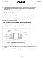
2.1 Bedding
Apply a 2mm (1/16") thick layer of marine sealant around the lip of the housing that
contacts the hull and up the sidewall of the housing. The sealant must extend 6mm
(1/4") higher than the combined thickness of the hull, washer(s), and hull nut (see
Figure 2). This will ensure there is sealant in the threads to seal the hull and to hold the
hull nut securely in place.
2.2 Installing
Caution: Never pull, carry, or hold the sensor by the cable as this may sever internal
connections.
1. From outside the hull, push the housing into the mounting hole using a twisting
motion to squeeze out excess sealant (see Figure 2). Align the arrow on the lip of
the housing to point forward toward the bow. If the sensor is not installed on the
centerline, angle the housing slightly toward the centerline to align it with the water
flow.
2. From inside the hull, slide the washer onto the housing. Aluminum hull less than
6mm (1/4") thick—Use an additional rubber, fiberglass, or plastic washer. Never
use bronze since electrolytic corrosion will occur. Never use wood since it will
swell, possibly fracturing the plastic housing.
3. Screw the hull nut in place being sure the notch on the upper rim of the housing
and the corresponding arrow on the lip are still positioned forward toward the bow.
(If your plastic housing has wrenching flats, do not clamp tightly, possibly causing
the housing to fracture.) Hand-tighten only. Do not over tighten. Wood hull—
Allow for the wood to swell.
4. Remove any excess sealant on the outside of the hull to ensure smooth water flow
over the paddlewheel. Warning: The O-rings must be intact and well lubricated to
make a watertight seal.

LOG TH52 English
10-7
5. After the sealant cures, inspect the O-rings on the valve assembly (replace if
necessary) and lubricate them with the silicone lubricant supplied (see Figure 3).
6. Slide the valve assembly into the housing being
sure to engage the key in the notch.
7. Screw the plastic cap nut in place and hand-tighten
only. Do not over tighten.
8. Attach one pull ring to the paddlewheel insert (see
Figure 5). Similarly, attach a pull ring to the blanking
plug.
9. Inspect the O-rings on the paddlewheel insert
(replace if necessary) and lubricate them with the
silicone lubricant supplied.
10. Slide the paddlewheel insert into the housing with
the arrows on the top pointing forward toward the
bow. Seat it into place with a pushing twisting
motion until the keys fit into the notches. The arrows
on the top of the insert, the notch in the housing,
and the arrow on the lip will be aligned. Be careful
not to rotate the housing and disturb the sealant.
11. Attach one safety ring to one end of the retaining
pin. Slide the retaining pin through the valve
assembly and paddlewheel insert. Attach the
second safety ring to the retaining pin (see Figure
2).
Warning: Always attach the safety wire to prevent

English LOG TH52
10-8
the insert from backing out in the unlikely event that
the cap nut fails or is screwed on incorrectly.
12. Attach the safety wire to one eye in the hull nut. Thread the short emergency plug
onto the wire. Lead the wire in a counterclockwise direction and thread it through
one eye in the cap nut. Thread the wire through the eye a second time. Then lead
the wire through the pull ring and the second eye in the cap nut. Twist the wire
securely to itself.
13. Route the cable to the instrument being careful not to tear the cable jacket when
passing it through the bulkhead(s) and other parts of the boat. To reduce electrical
interference, separate the sensor cable from other electrical wiring and the engine.
Coil any excess cable and secure it in place with zip-ties to prevent damage.
14. Refer to the instrument owner’s manual to connect the sensor to the instrument.
2.3 Checking for Leaks
Warning: Never install a thru-hull sensor and leave the boat in the water unchecked for
several days.
When the boat is placed in the water, immediately check around the thru-hull sensor
for leaks. Note that very small leaks may not be readily observed. It is best not to leave
the boat in the water for more than 3 hours before checking it again. If there is a small
leak, there may be considerable bilge water accumulation after 24 hour. If a leak is
observed, repeat ―Bedding‖ and ―Installing‖ on page 2 immediately.
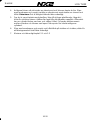
2.4 Installation in a Cored Fiberglass Hull
The core (wood or foam) must be cut and sealed carefully. The core must be protected
from water seepage, and the hull must be reinforced to prevent it from crushing under
the hull nut allowing the housing to become loose. Warning: Always wear safety
goggles and a dust mask.
1. Drill a 3mm or 1/8" pilot hole from inside the hull. If there is a rib, strut, or other hull
irregularity near the selected mounting location, drill from the outside. (If the hole is

LOG TH52 English
10-9
drilled in the wrong location, drill a second hole in a better location. Apply masking
tape to the outside of the hull over the incorrect hole and fill it with epoxy.)
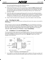
2. Using the 51mm or 2" hole saw, cut the hole from outside the hull through the
outer skin only (see Figure 4).
3. From inside the hull, use the 60mm or 2-3/8" hole saw to cut through the inner skin
and most of the core. The core material can be very soft. Apply only light pressure
to the hole saw after cutting through the inner skin to avoid accidentally cutting the
outer skin.
4. Remove the plug of core material so the inside of the outer skin and the inner core
of the hull are fully exposed. Sand and clean the inner skin, core, and the outer
skin around the hole. Caution: Completely seal the hull to prevent water seepage
into the core.
5. If you are skilled with fiberglass, saturate a layer of fiberglass cloth with a suitable
resin and lay it inside the hole to seal and strengthen the core. Add layers until the
hole is the correct diameter. Alternatively, a hollow or solid cylinder of the correct
diameter can be coated with wax and taped in place. Fill the gap between the
cylinder and hull with casting epoxy. After the epoxy has set, remove the cylinder.
6. Sand and clean the area around the hole, inside and outside, to ensure that the
sealant will adhere properly to the hull. If there is any petroleum residue inside the
hull, remove it with either mild household detergent or a weak solvent (alcohol)
before sanding.
7. Proceed with ―Bedding‖ and ―Installing‖ on page 2.

English LOG TH52
10-10
3 Operation, Maintenance
3.1 How the Valve Works
The sensor incorporates a self-closing valve which minimizes the flow of water into the
vessel when the paddlewheel insert is removed. The curved flap valve is activated by
both a spring and water pressure. Water pushes the flap valve upward to block the
opening so there is no gush of water into the boat.
WARNING: The valve is not a watertight seal!
Always install the paddlewheel insert or the long blanking plug secured with the
retaining pin, safety rings, and safety wire for a watertight seal.
3.2 Using the Long Blanking Plug
To protect the paddlewheel, use the long blanking plug when the boat will be kept in
salt water for more than a week, the boat will be removed from the water, or aquatic
growth build-up on the paddlewheel is suspected due
to inaccurate readings from the instrument.
Warning: The O-rings must be intact and well lubricated to make a watertight seal.
1. Inspect the O-rings on the long blanking plug (replace if necessary) and lubricate
them with the silicone lubricant supplied or petroleum jelly (Vaseline ® ) (see
Figure 5).
2. Remove the paddlewheel insert from the housing by removing the safety wire, one
safety ring, and the retaining pin.
Do not remove the cap nut (see Figure 2).
3. Grasp the pull ring and remove the paddlewheel insert with a slow pulling motion.
Note: In the unlikely event that the paddlewheel insert cannot be removed, see
―Servicing the Valve Assembly‖ on page 4.
Warning: Always attach the safety wire to prevent the insert from backing out in
the unlikely event that the cap nut fails or is screwed on incorrectly.
4. Slide the long blanking plug into the housing with the arrows on the top pointing
forward toward the bow. Seat it into place with a pushing twisting motion until the
keys fit into the notches (see Figure 5). Secure it with the retaining pin, safety
rings, and safety wire (see Figure 2).
3.3 Servicing the Paddlewheel Insert
Aquatic growth can impede or freeze the paddlewheel’s rotation and must be removed.
Use a stiff brush or putty knife to remove the growth and clean the surface with mild
household detergent. If fouling is severe, push the paddlewheel shaft out using a spare
shaft or a 4D finish nail with a flattened point. Then, lightly wet sand the surface with
fine grade wet/dry paper. The water lubricated paddlewheel bearings have a life of up
to 5 years on low-speed boats [less than 10kn (11MPH)] and 1 year on high-speed
vessels. Paddlewheels can fracture and shafts can bend due to impact with water
borne objects and mishandling in boat yards. O-rings must be free of abrasions and
cuts to ensure a watertight seal. A replacement Paddlewheel Kit 33-113 is available.

LOG TH52 English
10-11
1. Using the new paddlewheel shaft, push the old shaft out about 6mm (1/4"). With
pliers, remove the old shaft (see Figure 5).
2. Place the new paddlewheel in the cavity with the flat side of the blade facing the
same direction as the arrows on the top of the insert.
3. Tap the new shaft into place until the ends are flush with the insert.
4. Install two of the small O-rings.
5. Place the remaining two small O-rings on the long blanking plug.
6. To re-install the paddlewheel insert, see ―Installing‖ steps 9 through 12 in chapter
2.2.
3.4 Servicing the Valve Assembly
Should the valve fail, remove it for servicing. A replacement Paddlewheel & Valve Kit
33-415 is available.
1. Remove the short emergency plug from the safety wire (see Figure 2).
Warning: The O-ring must be intact and well lubricated to make a watertight seal.
2. ‘Inspect (replace if necessary) and lubricate the O-ring with silicone lubricant or
petroleum jelly (Vaseline ® ).
WARNING: When the valve assembly is removed, always insert the short
emergency plug with the cap nut and safety wire for a watertight seal.
3. Unscrew the cap nut. With the short emergency plug ready in one hand, remove
the paddlewheel insert and valve assembly as one unit by pulling upward on the
pull ring. Rapidly insert the short emergency plug to minimize the flow of water into
the boat.
Note: The plug is not secure until the cap nut is in place.
4. To free the cap nut, remove the paddlewheel insert from the valve assembly by
removing one safety ring and the retaining pin. Grasp the insert by the pull ring and
pull slowly upward.
WARNING: If the insert is caught in the valve assembly trapping the cap nut,
TEMPORARILY hold the short emergency plug in place with the safety wire.
Then, separate the insert from the valve assembly. If they cannot be separated
and the sensor must be left unattended, cut the cable [a minimum of 1m (3') from
the insert] to free the cap nut.
Warning: Always use the cap nut and safety wire to secure the short emergency
plug for a watertight seal.
5. Secure the short emergency plug with the cap nut. Hand-tighten only. Do not
overtighten. Re-attach the safety wire.
6. Separate the valve assembly from the paddlewheel insert.
7. Clean, repair, or replace the valve assembly, so the flap valve moves freely and
seats against the valve housing (see Figure 5).
Warning: The O-rings must be intact and well lubricated to make a watertight seal.

English LOG TH52
10-12
8. To reinstall the valve assembly and paddlewheel insert, inspect (replace if
necessary) and lubricate the O-rings on the valve assembly and the paddlewheel
insert with silicone lubricant or petroleum jelly.
9. Remove the safety wire and cap nut from the emergency plug. With the valve
assembly ready in one hand, remove the emergency plug. Rapidly slide the valve
assembly into the housing being sure to engage the key in the notch. Screw the
cap nut in place hand-tightening only. Do not over tighten.
10. Re-install the paddlewheel insert and secure it with the retaining pin and safety
rings. Attach the safety wire to the short emergency plug, the cap nut, and pull ring
(see Figure 2).

LOG TH52 English
10-13
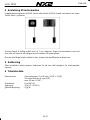
4 CONNECTION TO INSTRUMENT/CONTACTS
The log/temp transducer connects to the FI-30 Server or directly to the FI-30 Speed
Log.
The transducer cable is clearly marked with No 1 and the colours will correspond to
input screw terminal on the Server.
If the 8 m transducer cable needs to be cut, use the extra cable protectors supplied.
Press the protectors on to each wire with a pair of flat pliers.
5 CALIBRATION
Calibration is carried out in the Multi Control instrument or the speed log instrument
(see manual).
6 TECHNICAL DATA
Dimensions: Through-hull fitting 51 x
86 mm (1 5/8" x 3 3/8")
Hull thickness min 6 mm
(3/8"), max 42 mm (1 5/8")
Transducer cable: 8 m (26.2 ft)
Power suppIy: 12V DC (10-16V)
Power consumption: 0.06 W
Accuracy: ± 1%
Speed range 0.2-30 knots (depending on transducer type max. 90 knots)
Temperature range Operating -10°C to +70°C
Storage -35°C to +70°C

English LOG TH52
10-14
Monteringsinstruktion logg/temp givare
1 Generellt ............................................................................................................... 14
1.1 Användning ................................................................................................... 14
1.2 Verktyg och materiel ..................................................................................... 15
1.3 Test innan installation ................................................................................... 15
1.4 Bottenfärg ..................................................................................................... 15
1.5 Givarplacering .............................................................................................. 15
2 Installation ........................................................................................................... 17
2.1 Tätning .......................................................................................................... 17
2.2 Montering ...................................................................................................... 17
2.3 Kontrollera läckage ....................................................................................... 19
2.4 Installation i ett skrov med sandwich konstruktion ........................................ 19
3 Användning och underhåll ................................................................................. 21
3.1 Hur backventilen fungerar ............................................................................. 21
3.2 Användning av den långa blindpluggen ........................................................ 21
3.3 Service på paddelhjulsgivaren ...................................................................... 21
3.4 Service på backventilpluggen ....................................................................... 22
4 Anslutning till instrumenten ............................................................................... 23
5 Kalibrering ........................................................................................................... 23
6 Tekniska data ....................................................................................................... 23
1 Generellt
Logg/temp givaren med stoppventil är en paddelhjulsgivare som monteras genom
skrovet. Givarens höga noggrannhet passar såväl motor som segelbåtar.
VARNING: ANVÄND ALDRIG LÖSNINGSMEDEL
Rengörningsmedel, bensin, färg, tätningsmeddel och andra kemikalier kan innehålla
lösningsmedel. Så som aceton. Sådana lösningsmedel attackerar plaster och försvagar
materialet i stor grad.
1.1 Användning
Plastgenomföring rekommenderas för glasfiber och metallskrov. Använd inte
plastgenomföringar i träbåtar då rörelse i trät kan påverka plastens hållbarhet.
Bronsgenomföring (extra tillbehör) rekommenderas för glasfiber och träskrov.
Använd inte bronsgenomföringar i metallbåtar då galvaniska strömmar kan uppstå
och skada metallen.
Bordgenomföring i rostfritt stål rekommenderas för metallbåtar. Används för att
förhindra galvaniska strömmar .
Svensk
Viktigt: Vänligen läs igenom hela denna instruktion innan du börjar med
installationen. Om du har en annan monteringsmanual gäller denna om det finns
en skillnad.

LOG TH52 English
10-15
1.2 Verktyg och materiel
Vattenbaserad eller alkoholbaserad bottenfärg.
Skyddshandskar
Skyddsmask (för damm)
Borrmaskin med 10mm chuck
Borr 3mm
Hålsåg 51mm eller 2" (för plast och bronsgenomföring)
Hålsåg 57mm eller 2
1/4
" (rostfri bronsgenomföring)
Sandpapper
Milt rengörningsmedel (t.ex. alkohol)
Fil (installation i metallbåtar)
Tätningsmeddel för undervattensbruk (medföljer ej)
Extra bricka för aluminium skrov tunnare än 6mm
Buntband
Installation i glasfiberbåtar med sandwichskrov, se kapitel 2.4
Hålsåg för innerhålet 60mm eller 2-3/8"
Glasfiberväv, vax, tape och epoxi
1.3 Test innan installation
Anslut givaren till instrumentet eller Servern och snurra på paddelhjulet. Kontrollera att
instrumentet visar hastighet och att temperaturen visar ungefärlig lufttemperatur.
1.4 Bottenfärg
Beväxtning kan snabbt uppstå på givaren med begränsad funktionellitet som följd. Ytor
som utsätts för saltvatten måste skyddas med giftfärg. Obs. använd endast
vattenbaserad eller alkoholbaserad färg. Använd inte färg med andra
lösningsmeddel då de kan skada plasten. Måla ett nytt lager färg vid behov. Måla på
följande ytor (se figur 1):
På givarens utsida under O-ringen
Urtaget för paddelhjulet
paddelhjulet
Yttersidan av flänsen.
Insidan av bordgenomföringen upp till 30mm
Blindpluggens nederdel (under O-ringen)
1.5 Givarplacering
Turbulensfritt vatten måste passera givaren i alla farter. Välj en åtkomstbar plats inne i
båten. Se till att det finns minst 280mm ovan givaren så att det går att ta ur den.
Deplacementsmotorbåtar—Placera givaren midskepps nära centerlinjen..
Planande motorbåtar—Montera givaren så långt bak att givaren alltid .
Fenkölad segelbåt—givaren på eller så nära centerlinjen som möjlig och framför
kölen ca 300-600mm.
Svensk

English LOG TH52
10-16
Långkölad segelbåt—Placera givaren så nära centrum som möjligt. Där skrovet
lutar så lite som möjligt.
Observera: Montera inte givaren där turbulens eller luftbubblor kan uppstå: vid
bordgenomföringar, kanter, steg eller andra ojämnheter.
Observera: Montera inte loggivaren framför en ekolodsgivare då luftbubblor kan
genereras av loggivaren och störa ekolodet.
Svensk

LOG TH52 English
10-17
2 Installation
Glasfiberbåtar med sandwich skrov—Följ separat instruktion 2.4
Borrning
Varning: Använd alltid skyddshandskar och ansiktsmask.
1. Borra ett 3mm hål från insidan. Om det av olika anledningar inte går att borra från
insidan, borra utifrån.
2. Borra hålet för bordgenomföringen med hålsågen.
3. Slipa av ytan med sandpapper och tvätta sedan för att tätningsmedlet skall fästa
ordentligt. Om ytan är fet eller oljig, tvätta av med milt lösningsmeddel så som
alkohol eller liknande.
Metall skrov—Använd en fil och sandpapper för att avlägsna grader.
2.1 Tätning
Lägg på ett 2mm tjockt lager av marintätning för undervattensbruk på insidan av
flänsen (den sida som ligger mot skrovet) och på bordgenomföringens utsida. Lägg på
tätningsmedlet så att det gör 6mm högre än skrovets tjocklek, packning och mutter
tillsammans. Detta skall göras för att det säkert skall komma tätningsmedel i gängorna
innanför muttern. Det både tätar och låser muttern.
2.2 Montering
Varning: Bär eller lyft aldrig givaren i kabeln då detta kan skada givaren.
1. Tryck in genomföringen från utsidan i en roterande rörelse för att pressa ut
överskottet av tätningsmedlet. (se Figur 2). Set till att pilen på flänsens utsida
pekar framåt mot den punkt där stäven bryter vattnet. Om givaren inte sitter i
mitten skall den då peka lite inåt.
2. Trä på gummipackningen från insidan. Om skrovet är tunnare än 6mm måste en
extra packning av gummi, glasfiber eller plast användas. Använd aldrig brons i
aluminiumbåtar. Undvik även trä då det kan svälla och skada genomföringen.
3. Skruva på muttern från insidan, var noga med att givaren inte vrids utan
fortfarande pekar i rätt riktning. Dra åt muttern endast med handkraft. I träbåtar, se
till att inte dra åt så hårt utan lämna plats för trät att svälla.
4. Ta bort all överbliven tätningsmeddel på skrovets utsida så vattnet kan strömma
fritt och inte störas. Varning: O-ringarna måst vara hela och insmorda med fett för
att täta ordentligt.
Svensk

English LOG TH52
10-18
Svensk
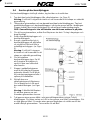
5. Då tätningsmassan har torkat, inspektera O-ringarna på backventilhuset (om
nödvändigt, byt ut dem) och smörj in dem med det medföljande silikonet. (se Figur
3).
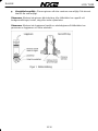
6. Stoppa i backventilhuset i genomföringen, se till att
styrpiggen hamnar i spåret (sitter på
genomföringens framkant)
7. Skruva på givarmuttern, dra åt med handkraft.
8. Montera en av låsringarna på paddelhjuslgivaren
(se Figur 5) och en på blindpluggen.
9. Kontrollera O-ringarna på paddelhjulsgivaren (byt
ut om nödvändigt) smörj in O-ringarna med det
medföljande silikonet.
10. Stoppa i paddelhjulsgivaren med de två pilarna på
toppen pekandes framåt. Se till att de två
orienteringpiggarna faller i spåren på framkanten.
11. Sätt på den ena säkerhetsringen på låspinnen. För
in låspinnen och lås med den andra låsringen. (se
Figur 2).
Varning: Sätt alltid dit låswiren för att låsa givaren
om mot förmodan givarmuttern lossnar.
12. Trä igenom wiren genom hålet i ena
genomföringsmutterns vingar Trä på blindpluggen.
För wiren moturs och för in den genom ena hålet i
givarmuttern. Gör en ögla genom hålet. För sedan

LOG TH52 English
10-19
wiren genom dragöglan och vidare ner till det andra hålet på givarmuttern. Tvinna
wiren för att låsa.
13. Dra kabeln till Servern eller instrumentet. Om det är trångt och det finns risk att
stiftkontakten skadas, skruva bort kontakten, dra kabeln och montera sedan
kontakten igen.
14. För elektrisk installation, se kapitel Fel! Hittar inte referenskälla..
2.3 Kontrollera läckage
Varning: Installera aldrig en genomföring och lämna båten utan tillsyn en längre tid.
När båten sjösatts, kontrollera direkt runt genomföringen om det finns läckor.
Observera att små läckor kan vara svåra att upptäcka. Du bör inte lämna båten mer än
tre timmar innan du kontrollerar igen. Även om det är en liten läcka kan det samlas
mycket vatten i kölsvinet efter 24 timmar. Om du upptäcker läckage, upprepa
proceduren för montage och tätning.
2.4 Installation i ett skrov med sandwich konstruktion
Kärnan (trä eller skum) måste skäras bort och tätas. Kärnan måste tätas mot
vatteninträngning. Skrovet måste också förstärkas så att det inte trycks ihop och
genomföringsmuttern lossnar.. Varning: Använd alltid skyddshandskar och
skyddsmask.
1. Borra ett 3mm hål från insidan. Om det av olika anledningar inte går att borra från
insidan, borra utifrån)
2. Använd en 51mm hålsåg från utsidan men skär endast igenom ytterskrovet. (se
Figur 4).
3. Använd en 60mm hålsåg från utsidan. Skär igenom innerskrovet och det mesta av
kärnan. Kärnan kan vara mycket mjuk så se till att vara lätt på handen.
Svensk
Sidan laddas...
Sidan laddas...
Sidan laddas...
Sidan laddas...
Sidan laddas...
Sidan laddas...
-
 1
1
-
 2
2
-
 3
3
-
 4
4
-
 5
5
-
 6
6
-
 7
7
-
 8
8
-
 9
9
-
 10
10
-
 11
11
-
 12
12
-
 13
13
-
 14
14
-
 15
15
-
 16
16
-
 17
17
-
 18
18
-
 19
19
-
 20
20
-
 21
21
-
 22
22
-
 23
23
-
 24
24
-
 25
25
-
 26
26


på andra språk
- English: Garmin Nexus Owner's manual
Relaterade papper
-
Garmin Nexus Bruksanvisning
-
-
-
Garmin GNX Bezicni komplet za jedrenje sa sondama od 43 mm Installationsguide
-
-
-
Garmin Panoptix™ PS51-TH Installationsguide
-
Garmin NMEA 0183 Användarmanual
-
Garmin striker 4 Användarmanual
-
Garmin Dvofrekvencni pretvornik Garmin Installationsguide
