
TRANSMIT RE-NAME CLEAR
MACRO
MACROLEARN
OFF ON
SYSTEM
POWER
STANDBY
V-AUX TAPE PHONO
D-TV CBL/SAT TUNER MD CD
VCR 1 VCR 2 VCR 3 LD DVD
6CH INPUT
TITLE
ENTER
MENU
SOUND
DISPLAY
SOURCE
SELECT
SEARCH CHAPTER
%
!
!
$
*#
$
%
%
%
%
%
10KEY DSP HALL 1 HALL 2 CHURCH JAZZ CLUB
ROCK
CONCERT
ENTER-
TAINMENT
CONCERT
VIDEO 2
CONCERT
VIDEO 1
POWER REC STOP PAUSE PLAY
EX/ES
TV
THEATER
MOVIE
THEATER 2
MOVIE
THEATER 1
/DTS
SUR.
0 +10 +100
1234
5678
9101112
++ +
TV VOL
A / B / C / D / E
PRESET
TV INPUT
TV MUTE
CH
DISC
MUTE
EFFECT
VOLUME
+–
/
CHP/INDEX
–– –
PHONES BASS TREBLE
NATURAL SOUND AV RECEIVER
RX-V1
INPUT MODE
INPUT SELECTOR
VOLUME
S VIDEO VIDEO L RAUDIO
VIDEO AUX
CINEMA DSP
DOLBY
DIGITAL
DIGITAL
SURROUND
ON OFF
55
44
33
22
11
0
+
–
55
44
33
22
11
0
+
–
55
44
33
22
11
0
RL
VCR 2 CD
VCR 1
TUNER
CBL/SAT TAPE
D-TV
MD
LD
DVD
BALANCE
PHONOVCR 3
VIDEO AUX
REC OUT/ZONE 2
SOURCE/REMOTE
BASS
EXTENSION
PROCESSOR
DIRECT
STANDBY/ON
6CH IMPUT
PROGRAM PRESET/TUNING
EFFECT
A/B/C/D/E
SPEAKERS
AB
PRESET/TUNING
EDIT
FM/AM MEMORY
MANL/AUTO FM
TUNING MODE
AUTO/MANL MONO
RX-V1
Natural Sound AV Receiver
Ampli-Tuner Audio-Video
UCA
OWNER’S MANUAL
MODE D’EMPLOI

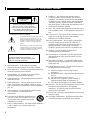
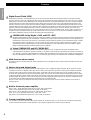
• Explanation of Graphical Symbols
The lightning flash with arrowhead symbol, within an
equilateral triangle, is intended to alert you to the
presence of uninsulated “dangerous voltage” within
the product’s enclosure that may be of sufficient
magnitude to constitute a risk of electric shock to
persons.
The exclamation point within an equilateral triangle
is intended to alert you to the presence of important
operating and maintenance (servicing) instructions in
the literature accompanying the appliance.
1 Read Instructions – All the safety and operating
instructions should be read before the unit is operated.
2 Retain Instructions – The safety and operating instructions
should be retained for future reference.
3 Heed Warnings – All warnings on the unit and in the
operating instructions should be adhered to.
4 Follow Instructions – All operating and other instructions
should be followed.
5 Water and Moisture – The unit should not be used near
water – for example, near a bathtub, washbowl, kitchen
sink, laundry tub, in a wet basement, or near a swimming
pool, etc.
6 Carts and Stands – The unit should be used only with a
cart or stand that is recommended by the
manufacturer.
6A A unit and cart combination should be moved
with care. Quick stops, excessive force, and
uneven surfaces may cause the unit and cart
combination to overturn.
7 Wall or Ceiling Mounting – The unit should be mounted to
a wall or ceiling only as recommended by the
manufacturer.
8 Ventilation – The unit should be situated so that its
location or position does not interfere with its proper
ventilation. For example, the unit should not be situated
on a bed, sofa, rug, or similar surface, that may block the
ventilation openings; or placed in a built-in installation,
such as a bookcase or cabinet that may impede the flow of
air through the ventilation openings.
9 Heat – The unit should be situated away from heat sources
such as radiators, stoves, or other appliances that produce
heat.
10 Power Sources – The unit should be connected to a power
supply only of the type described in the operating
instructions or as marked on the unit.
11 Power-Cord Protection – Power-supply cords should be
routed so that they are not likely to be walked on or
pinched by items placed upon or against them, paying
particular attention to cords at plugs, convenience
receptacles, and the point where they exit from the unit.
12 Cleaning – The unit should be cleaned only as
recommended by the manufacturer.
13 Nonuse Periods – The power cord of the unit should be
unplugged from the outlet when left unused for a long
period of time.
14 Object and Liquid Entry – Care should be taken so that
objects do not fall into and liquids are not spilled into the
inside of the unit.
15 Damage Requiring Service – The unit should be serviced
by qualified service personnel when:
A. The power-supply cord or the plug has been
damaged; or
B. Objects have fallen, or liquid has been spilled into the
unit; or
C. The unit has been exposed to rain; or
D. The unit does not appear to operate normally or
exhibits a marked change in performance; or
E. The unit has been dropped, or the cabinet damaged.
16 Servicing – The user should not attempt to service the unit
beyond those means described in the operating
instructions. All other servicing should be referred to
qualified service personnel.
17 Power Lines – An outdoor antenna should be located away
from power lines.
18 Grounding or Polarization – Precautions should be taken
so that the grounding or polarization is not defeated.
WARNING
TO REDUCE THE RISK OF FIRE OR
ELECTRIC SHOCK, DO NOT EXPOSE THIS
UNIT TO RAIN OR MOISTURE.
CAUTION: TO REDUCE THE RISK OF
ELECTRIC SHOCK, DO NOT REMOVE
COVER (OR BACK). NO USER-SERVICEABLE
PARTS INSIDE. REFER SERVICING TO
QUALIFIED SERVICE PERSONNEL.
RISK OF ELECTRIC SHOCK
DO NOT OPEN
CAUTION
I
SAFETY INSTRUCTIONS
I

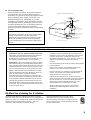
19 For US customers only:
Outdoor Antenna Grounding – If an outside antenna is
connected to this unit, be sure the antenna system is
grounded so as to provide some protection against voltage
surges and built-up static charges. Article 810 of the
National Electrical Code, ANSI/NFPA 70, provides
information with regard to proper grounding of the mast
and supporting structure, grounding of the lead-in wire to
an antenna discharge unit, size of grounding conductors,
location of antenna discharge unit, connection to
grounding electrodes, and requirements for the grounding
electrode.
FCC INFORMATION (for US customers only)
We Want You Listening For A Lifetime
YAMAHA and the Electronic Industries Association’s Consumer
Electronics Group want you to get the most out of your equipment by
playing it at a safe level. One that lets the sound come through loud
and clear without annoying blaring or distortion – and, most
importantly, without affecting your sensitive hearing.
Since hearing damage from loud sounds is often
undetectable until it is too late, YAMAHA and the
Electronic Industries Association’s Consumer Electronics
Group recommend you to avoid prolonged exposure from
excessive volume levels.
Compliance with FCC regulations does not guarantee that
interference will not occur in all installations. If this product
is found to be the source of interference, which can be
determined by turning the unit “OFF” and “ON”, please try to
eliminate the problem by using one of the following
measures:
Relocate either this product or the device that is being affected
by the interference.
Utilize power outlets that are on different branch (circuit
breaker or fuse) circuits or install AC line filter/s.
In the case of radio or TV interference, relocate/reorient the
antenna. If the antenna lead-in is 300 ohm ribbon lead,
change the lead-in to coaxial type cable.
If these corrective measures do not produce satisfactory
results, please contact the local retailer authorized to distribute
this type of product. If you can not locate the appropriate
retailer, please contact Yamaha Electronics Corp., U.S.A.
6660 Orangethorpe Ave, Buena Park, CA 90620.
The above statements apply ONLY to those products
distributed by Yamaha Corporation of America or its
subsidiaries.
1. IMPORTANT NOTICE : DO NOT MODIFY THIS UNIT!
This product, when installed as indicated in the instructions
contained in this manual, meets FCC requirements.
Modifications not expressly approved by Yamaha may void
your authority, granted by the FCC, to use the product.
2. IMPORTANT : When connecting this product to accessories
and/or another product use only high quality shielded cables.
Cable/s supplied with this product MUST be used. Follow all
installation instructions. Failure to follow instructions could
void your FCC authorization to use this product in the USA.
3. NOTE : This product has been tested and found to comply
with the requirements listed in FCC Regulations, Part 15 for
Class “B” digital devices. Compliance with these
requirements provides a reasonable level of assurance that
your use of this product in a residential environment will not
result in harmful interference with other electronic devices.
This equipment generates/uses radio frequencies and, if not
installed and used according to the instructions found in the
users manual, may cause interference harmful to the operation
of other electronic devices.
Note to CATV system installer:
This reminder is provided to call the CATV system installer’s
attention to Article 820-40 of the NEC that provides
guidelines for proper grounding and, in particular, specifies
that the cable ground shall be connected to the grounding
system of the building, as close to the point of cable entry as
practical.
EXAMPLE OF ANTENNA GROUNDING
MAST
GROUND
CLAMP
ANTENNA
LEAD IN
WIRE
ANTENNA
DISCHARGE UNIT
(NEC SECTION 810–20)
GROUNDING CONDUCTORS
(NEC SECTION 810–21)
GROUND CLAMPS
POWER SERVICE GROUNDING
ELECTRODE SYSTEM
(NEC ART 250. PART H)
ELECTRIC
SERVICE
EQUIPMENT
NEC
– NATIONAL ELECTRICAL CODE
II
II

1. To assure the finest performance, please read this manual
carefully. Keep it in a safe place for future reference.
2. Install this unit in a cool, dry, clean place – away from
windows, heat sources, sources of excessive vibration,
dust, moisture and cold. Avoid sources of humming
(transformers, motors). To prevent fire or electrical shock,
do not expose the unit to rain or water.
3. Never open the cabinet. If something drops into the set,
contact your dealer.
4. Do not use force on switches, controls or connection
wires. When moving the unit, first disconnect the power
plug and the wires connected to other equipment. Never
pull the wires themselves.
5. The openings on the cover assure proper ventilation of the
unit. If these openings are obstructed, the temperature
inside the unit will rise rapidly. Therefore, avoid placing
objects against these openings, and install the unit in a
well-ventilated area to prevent fire and damage.
6. The voltage used must be the same as that specified on this
unit. Using this unit with a higher voltage than specified is
dangerous and may result in fire or other accidents.
YAMAHA will not be held responsible for any damage
resulting from the use of this unit with a voltage other than
that specified.
7. Digital signals generated by this unit may interfere with
other equipment such as tuners, receivers and TVs. Move
this unit farther away from such equipment if interference
is observed.
8. Do not attempt to clean the unit with chemical solvents;
this might damage the finish. Use a clean, dry cloth.
9. Be sure to read the “Troubleshooting” section regarding
common operating errors before concluding that the unit is
faulty.
10. When not planning to use this unit for a long period of
time (e.g., a vacation), disconnect the AC power plug from
the wall outlet.
11. To prevent lightning damage, disconnect the AC power
plug and disconnect the antenna cable when there is an
electrical storm.
12. Grounding or polarization – Precautions should be taken
so that the grounding or polarization of the unit is not
defeated.
13. AC outlet
Do not connect audio equipment to the AC outlet on the
rear panel if that equipment requires more power than the
outlet is rated to provide.
This unit is not disconnected from the AC power source as long as
it is connected to the wall outlet, even if this unit itself is turned
off. This state is called the standby mode. In this state, this unit is
designed to consume a very small quantity of power.
IMPORTANT
Please record the serial number of this unit in the space below.
MODEL:
Serial No.:
The serial number is located on the rear of the unit.
Retain this Owner’s Manual in a safe place for future reference.
FOR CANADIAN CUSTOMERS
To prevent electric shock, match wide blade of plug to wide slot
and fully insert.
This Class B digital apparatus complies with Canadian ICES-003.
Manufactured under license from Dolby Laboratories. “Dolby”, “AC-
3”, “Pro Logic”, “Surround EX” and the double-D symbol are
trademarks of Dolby Laboratories.
Confidential Unpublished Works. 1992-1997 Dolby Laboratories,
Inc. All rights reserved.
Manufactured under license from Digital Theater Systems, Inc. US
Pat. No. 5,451,942 and other world-wide patents issued and pending.
“DTS”, “DTS Digital Surround” and “DTS ES” are trademarks of
Digital Theater Systems, Inc. Copyright 1996 Digital Theater
Systems, Inc. All Rights Reserved.
III
CAUTION: READ THIS BEFORE OPERATING YOUR UNIT.

1
English
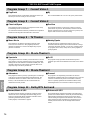
Contents
Introduction 2
Features ............................................................................................................... 3
Getting Started .................................................................................................... 5
Controls and Functions ....................................................................................... 6
Preparations 12
Speaker System Configurations ........................................................................ 13
Speaker Placement ............................................................................................ 14
Hookups ............................................................................................................ 15
On-Screen Displays (OSD) ............................................................................... 26
Speaker Settings ................................................................................................ 27
Speaker Output Levels ...................................................................................... 27
Basic Operation 30
Basic Playback .................................................................................................. 31
AM/FM Tuner................................................................................................... 35
Basic Recording ................................................................................................ 39
Advanced Operation 40
SET MENU Items ............................................................................................. 41
Remote Control Features .................................................................................. 54
Adjusting the Levels of the Effect Speakers ..................................................... 67
Setting the Sleep Timer..................................................................................... 67
ZONE 2 ............................................................................................................. 68
Addtional Information 70
Digital Sound Field Processing (DSP).............................................................. 71
Hi-Fi DSP-Sound Field Program ...................................................................... 72
CINEMA-DSP .................................................................................................. 73
CINEMA-DSP Sound Field Program ............................................................... 75
Sound Field Program Parameter Editing .......................................................... 77
Digital Sound Field Parameter Descriptions..................................................... 78
Appendix 82
Troubleshooting ................................................................................................ 83
Reference Chart for the INPUT and OUTPUT Jacks ....................................... 87
CINEMA - EQ Frequency Characteristics ....................................................... 87
Specifications .................................................................................................... 88

2
Introduction
Introduction
Features 3
Introduction ......................................................................................................... 3
Dolby Digital and Dolby Digital Surround EX .................................................. 3
DTS and DTS ES ................................................................................................ 3
Comparing Surround Technologies .................................................................... 3
Digital Sound Fields (DSP) ................................................................................ 4
Multi-function remote control............................................................................. 4
Various Input and Output Jacks .......................................................................... 4
Built-in 8-channel power amplifier..................................................................... 4
Custom installation facility ................................................................................. 4
Getting Started 5
Checking the Package Contents .......................................................................... 5
Installing Batteries in the Remote Control.......................................................... 5
Using the Remote Control .................................................................................. 5
Controls and Functions 6
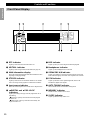
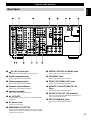
Front Panel .......................................................................................................... 6
Opening and Closing the Front Panel Door ........................................................ 7
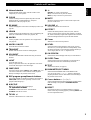
Remote Control ................................................................................................... 8
Front Panel Display........................................................................................... 10
Rear Panel ......................................................................................................... 11

3
English
Introduction
Welcome to the exciting world of digital home entertainment. The RX-V1 is the most complete and advanced AV receiver available.
Though some of the more advanced features of this unit may not be familiar to you, they are easy to use. Incorporated state-of-the-art
technology such as Dolby Digital and DTS can bring the same audio experience to your home as they have brought to feature films in
quality theaters around the world. To make the listening experience even more enjoyable, the RX-V1 includes a number of exclusive,
digitally created listening environments known as digital sound fields. Choosing a sound field program is like transporting yourself to
such venues as an outdoor arena, an European church, or a cozy jazz club. Take some time now to read more about these features and
enjoy the new experiences the RX-V1 brings to your home theater.
Dolby Digital and Dolby Digital Surround EX
The RX-V1 is equipped with a Dolby Digital decoder which reproduces industry standard Dolby Digital surround sound for a cinematic
audio experience in your home. Dolby Digital is a 5.1 channel format because it uses five discrete channels (left and right Main
channels, Center channel, and left and right Rear channels) and a special low frequency channel (that is used only enough to merit the
“0.1” channel rating) to create incredibly realistic 360˚ surround effects. Recently, Dolby Digital Surround EX was introduced in movie
theaters as an advanced surround technology. The addition of a Rear Center channel makes front-to-back transitions more realistic. You
can enjoy the newest Dolby Digital Surround EX software with the CINEMA DSP programs in the RX-V1 such as Dolby Digital/
Matrix 6.1.
DTS and DTS ES
The RX-V1 is also equipped with a DTS decoder, which uses a 5.1 channel system to create a full surround sound environment. It was
developed as a way to replace the analog soundtracks of movies with six channels of digital sound. In comparison with Dolby Digital,
DTS uses less compression to store the sound information. The newly presented DTS ES system reproduces digital sound similar to
Dolby Digital Surround EX. The use of the Rear Center speaker along with the existing 5.1 channel speakers provides a fully immersive
cinematic audio experience.
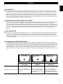
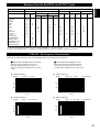
Comparing Surround Technologies
To enjoy dynamic feature film sound at home, you should have the appropriate sound reproduction system for your home theater. The
traditional standard for home surround systems was called Dolby Surround and consisted of four channels (left and right Main channels,
a Center channel, and a Surround channel for effects). The new home theater standard is Dolby Digital and consists of 5.1 channels (left
and right Main channels, a Center channel, left and right Rear channels, and an LFE (low frequency effect) channel). The newer DTS
surround technology also makes use of a 5.1 channel system. The 6.1 channel system which adds a Rear Center channel to the 5.1
channel configuration is the latest advancement in surround sound technology, and is employed by Dolby Digital Surround EX and DTS
ES.
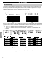
Features
Reproduction Channel System
Dolby Surround
(Pro Logic)
Dolby Digital
and DTS
Dolby Digital Surround EX
and DTS ES
L
S
CR
S
L
RL
CR
RR
SW
RC
L
RL
CR
RR
SW
4 channels
Left (L) and right (R) Main,
Center (C), and Surround (S)
channels
5.1 channels
Left (L) and right (R) Main,
Center (C), left and right Rear
(RL and RR), and Subwoofer
(SW) channels
6.1 channels
Left (L) and right (R) Main,
Center (C), left and right Rear
(RL and RR), Rear Center (RC),
and Subwoofer (SW) channels

4
Introduction
Features
Digital Sound Fields (DSP)
Technological advances in sound reproduction over the last 30 years have enhanced the listening experience with improved clarity,
precision, and power. However, something has been missing: the atmosphere and acoustic ambience of the public venue. Our Yamaha
engineers have extensively researched the nature of sound acoustics and the way sound reflects inside a room. We sent these engineers
to famous theaters and concert halls around the world to measure the acoustics of those venues with sophisticated microphones. The
data they collected is used to recreate these environments in digital sound fields. Some of these digital sound fields have been created
using data measured at the original venue; others have been created from combinations of data to form unique environments for specific
purposes. Some have been designed especially for music, and others especially for movies. Of course, this only solves half of the
problem. Because these engineers have no way of knowing the acoustics of your entertainment room, we have made it possible for you
to adjust the various parameters of this data to tailor each virtual venue to your taste. You can use these sound fields to enhance any
source and in combination with any of the following surround sound technologies.
CINEMA-DSP: Dolby Digital + DSP and DTS + DSP
The Dolby Digital system and DTS system show their full capability in large movie theaters, because feature film soundtracks are
designed to be reproduced in such environments. It is difficult to recreate a sound environment similar to a movie theater in your
entertainment room because of the room size, wall materials, and the number of speakers in your entertainment system. Yamaha
DSP technology makes it possible for you to enjoy nearly the same sound experience as that of a large movie theater in your
entertainment room by compensating for lack of presence and dynamics in your entertainment room with Yamaha’s original
digital sound fields combined with Dolby Digital or DTS soundtracks.
Virtual CINEMA DSP and HP CINEMA DSP
Yamaha developed the Virtual CINEMA DSP algorithm which allows you to experience the virtual sound fields without
surround speakers. This makes it possible for the RX-V1 to produce a full surround sound catering to the number of speakers you
have. The RX-V1 also has an HP (Headphones) CINEMA DSP algorithm which is achieved by the crosstalk processing applying
the precise Head Related Transfer Function. You can therefore enjoy listening to the CINEMA DSP soundfields on headphones.
Multi-function remote control
The remote control can operate other audio-video components once you program the remote control using the manufacturer code and
Learn feature.
Various Input and Output Jacks
The RX-V1 has various output jacks for audio and video signals as well as a digital recording output jack. Many input jacks are also
available for connection to multiple audio-video sources. All the video inputs and outputs have S-video jacks in addition to standard
composite video jacks for improved video picture quality. Component video input and output jacks are also available to deliver the
excellent video signals from DVD players and other high quality video sources. The coaxial and optical digital signal jacks (provided
for direct transmission of digital signals) automatically detect Dolby Digital, DTS, and PCM signals. A demodulator circuit is built into
the Dolby Digital RF input so you can connect it directly to the Dolby Digital RF signal output on your LD player. Additionally, there
are six audio inputs for disscrete multichannel reproduction from an external decoder.
The RX-V1 also comes with a monaural subwoofer jack and split subwoofer jacks which can reproduce delicate but powerful low
frequency effects.
Built-in 8-channel power amplifier
Main: 110 W + 110 W (8Ω) RMS Output Power, 0.015% THD, 20-20,000 Hz
Center: 110 W (8Ω) RMS Output Power, 0.015% THD, 20-20,000 Hz
Rear: 110 W + 110 W (8Ω) RMS Output Power, 0.015% THD, 20-20,000 Hz
Front: 35 W + 35 W (8Ω) RMS Output Power, 0.05% THD, 1 kHz
Rear Center: 110 W (8Ω) RMS Output Power, 0.015% THD, 20-20,000 Hz
Custom installation facility
You can make up a multi-room audio-video system with this unit. With this feature, you can set this unit to reproduce separate input
sources in the main room and in a second (ZONE 2) room using the supplied remote control in the second room.

5
English
PHONES BASS TREBLE
NATURAL SOUND AV RECEIVER
RX-V1
INPUT MODE
INPUT SELECTOR
VOLUME
S VIDEO VIDEO L RAUDIO
VIDEO AUX
CINEMA DSP
DOLBY
DIGITAL
DIGITAL
SURROUND
ON OFF
55
44
33
22
11
0
+
–
55
44
33
22
11
0
+
–
55
44
33
22
11
0
RL
VCR 2 CD
VCR 1
TUNER
CBL/SAT TAPE
D-TV
MD
LD
DVD
BALANCE
PHONOVCR 3
VIDEO AUX
REC OUT/ZONE 2
SOURCE/REMOTE
BASS
EXTENSION
PROCESSOR
DIRECT
STANDBY/ON
6CH IMPUT
PROGRAM PRESET/TUNING
EFFECT
A/B/C/D/E
SPEAKERS
AB
PRESET/TUNING
EDIT
FM/AM MEMORY
MANL/AUTO FM
TUNING MODE
AUTO/MANL MONO
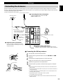
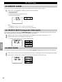
30° 30°
Approximately 6m (20 feet)
Reset button
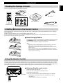
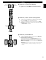
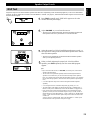
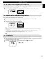
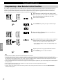
Checking the Package Contents
Check your package to make sure it has the following items.
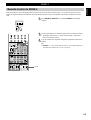
Remote Control
Alkaline Batteries (3) (LR6)
Installing Batteries in the Remote Control
Insert the batteries in the correct direction by aligning the + and – marks on the batteries with the polarity illustrations (+ and –) inside the
battery compartment.
Change the batteries periodically. Do not use old batteries together with new ones.
Do not use different types of batteries (such as alkaline and manganese batteries) together. Read the packaging carefully as these different
types of batteries may have the same shape and color.
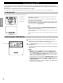
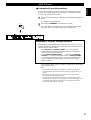
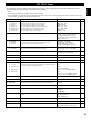
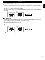
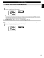
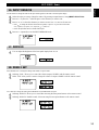
■ About Changing Batteries
As the batteries wear out, the operating range of the remote control decreases and
the TRANSMIT indicator does not flash or its light becomes dim. When you
notice any of these conditions, change all of the batteries.
Notes:
• If the remote control is without batteries for more than 20 minutes, or if worn out
batteries remain in the unit, the contents of the memory may be cleared.
If the memory is cleared, insert new batteries and reprogram any functions that may
have been cleared.
• After you insert new batteries, be sure to push RESET in the battery compartment
using a ball point pen or similar object before using the remote control. (This does not
clear the contents of the memory.)
Getting Started
TRANSMIT RE-NAME CLEAR
MACRO
MACROLEARN
OFF ON
SYSTEM
POWER
STANDBY
V-AUX TAPE PHONO
D-TV CBL/SAT TUNER MD CD
VCR 1 VCR 2 VCR 3 LD DVD
6CH INPUT
TITLE
ENTER
MENU
SOUND
DISPLAY
SOURCE
SELECT
SEARCH CHAPTER
%
!
!
$
* #
$
%
%
%
%
%
10KEY DSP HALL 1 HALL 2 CHURCH JAZZ CLUB
ROCK
CONCERT
ENTER-
TAINMENT
CONCERT
VIDEO 2
CONCERT
VIDEO 1
POWER REC STOP PAUSE PLAY
EX/ES
TV
THEATER
MOVIE
THEATER 2
MOVIE
THEATER 1
/DTS
SUR.
0 +10 +100
1 2 3 4
5 6 7 8
9 10 11 12
+ + +
TV VOL
A / B / C / D / E
PRESET
TV INPUT
TV MUTE
CH
DISC
MUTE
EFFECT
VOLUME
+–
/
CHP/INDEX
– – –
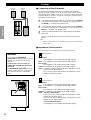
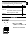
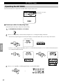
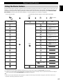
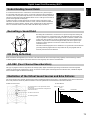
Using the Remote Control
The remote control transmits a directional infrared beam. Be sure to aim the remote control directly at the remote control sensor on the main
unit during operation. When the sensor is covered or there is a large object between the remote control and the main unit, the sensor cannot
receive signals. The sensor may not be able to receive signals properly when it is exposed to direct sunlight or a strong artificial light (such as
a fluorescent or strobe light). In this case, change the direction of the light or reposition the main unit to avoid direct lighting.
■ About handling the remote control
Handle the remote control with care.
Do not spill water or other liquids on the remote control.
Do not drop the remote control.
Do not leave or store the remote control in the following types of conditions:
• high humidity or temperature such as near a heater, stove or bath; or
• dusty places; or
• in places subject to extremely low temperatures.
AM Loop Antenna
FM Antenna
Antenna Adapter
(U.S.A. and Canada Models only)
FAST FORWARD
REC / PAUSE
REWIND
DECK A / DECK B
DIRECTION A/B
PLAY
STOP
Setup Section
Power Buttons
Display Window
Program/10Key Section
Others
Source Select
Operation Section
Volume Section
Programming Section
Input Section
POWER
(Preset Group) A
(Preset Group) B
(Preset Group) D
(Preset Group) E
PRESET
NUMBER 1~8
(Preset Group)
A/B/C/D/E
(Preset Group) C
PRESET + / –
POWER
STOP
INDEX
SEARCH
DISPLAY
SKIP SEARCH
+10
0
PLAY
PAUSE (YAMAHA
:
PAUSE / STOP)
CLEAR
1~9
DISC SKIP
POWER
REC PAUSE
SEARCH
DISPLAY
SKIP SEARCH
+10
0
PLAY
PAUSE
STOP
1~9
Quick Reference Card
Quick Reference Guide

6
Introduction
Controls and Functions
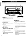
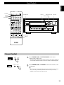
Front Panel
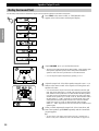
~ STANDBY/ON
Turns this unit on (On mode) and off (Standby mode). When
you turn on this unit, you will hear a click and there will be a
four to five to second delay before this unit can reproduce
sound.
In Standby mode, this unit consumes a small amount of power
so it can respond to the remote control.
Ÿ Remote Control Sensor
Receives signals from the remote control.
! Front Panel Display
Shows information about the operational status of this unit (see
page 10).
⁄ INPUT MODE
Selects the mode of input for sources that output two or more
types of signals to this unit (see page 33).
You cannot control the input mode when you select 6CH
INPUT as the input source.
@ INPUT SELECTOR
Selects the input source (DVD, LD, D-TV, CBL/SAT,
VCR 1, VCR 2, VCR 3, V-AUX, PHONO, CD, TUNER,
TAPE, MD) you want to listen to or watch.
¤ VOLUME
Controls the output level of all audio channels.
This does not affect the REC OUT level.
# PHONES
Outputs audio signals for private listening using headphones.
When you connect headphones, no signals are output to the
PREOUT jacks or the speakers.
‹ SPEAKERS A/B
When pushed in (ON), these buttons turn on the set of Main
speakers connected to the A and/or B terminals on the rear
panel.
$ BASS
Adjusts the low frequency response for the left and right Main
speaker channels.
Turn the control to the right to increase the low frequency
response and turn the control to the left to decrease the low
frequency response.
If you increase or decrease the low frequency sound to an
extreme level, the tonal quality from the Center, Front Effect,
Rear Center, and Rear speakers may not match that of the left
and right Main speakers.
› PROGRAM /
Selects the sound field program (see page 34).
Selecting a sound field program turns on the effect.
% TREBLE
Adjusts the high frequency response for the left and right
main channels.
Turn the control to the right to increase the high frequency
response and turn the control to the left to decrease the high
frequency response.
If you increase or decrease the high frequency sound to an
extreme level, the tonal quality from the Center, Front Effect,
Rear Center, and Rear speakers may not match that of the left
and right Main speakers.
PHONES BASS TREBLE
NATURAL SOUND AV RECEIVER
RX-V1
INPUT MODE
INPUT SELECTOR
VOLUME
S VIDEO VIDEO L RAUDIO
VIDEO AUX
CINEMA DSP
DOLBY
DIGITAL
DIGITAL
SURROUND
ON OFF
55
44
33
22
11
0
+
–
55
44
33
22
11
0
+
–
55
44
33
22
11
0
RL
VCR 2 CD
VCR 1
TUNER
CBL/SAT TAPE
D-TV
MD
LD
DVD
BALANCE
PHONOVCR 3
VIDEO AUX
REC OUT/ZONE 2
SOURCE/REMOTE
BASS
EXTENSION
PROCESSOR
DIRECT
STANDBY/ON
6CH IMPUT
PROGRAM PRESET/TUNING
EFFECT
A/B/C/D/E
SPEAKERS
AB
PRESET/TUNING
EDIT
FM/AM MEMORY
MANL/AUTO FM
TUNING MODE
AUTO/MANL MONO
PRESET/TUNING
EDIT
FM/AM MEMORY
MANL/AUTO FM
TUNING MODE
AUTO/MANL MONO
%
%

7
English
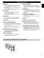
( REC OUT/ZONE2
Selects the source you want to direct to the audio/video
recorder and ZONE 2 outputs independent of the source you
are listening to in the main room. When set to the SOURCE/
REMOTE position, the input source is directed to all outputs.
· VIDEO AUX
Inputs audio and video signals from a portable external source
such as a video camera. To reproduce source signals from these
jacks, select V-AUX as the input source. To direct this source
to the VCR 1 output jacks, select VIDEO AUX using REC
OUT/ZONE 2.
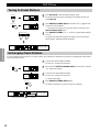
) PRESET/TUNING (EDIT)
Switches the function of PRESET/TUNING / (the colon
“:” turns on or off).
This button is also used to exchange the places of two preset
stations with each other.
‚ FM/AM
Switches the reception band between FM and AM.
_ MEMORY (MAN’L/AUTO FM)
Enters a station into memory. See “Manually presetting
stations” on page 36 for details. Hold down this button for more
than three seconds to start automatic preset tuning. See
“Automatically presetting stations” on page 37 for details.
— TUNING MODE (AUTO/MAN’L MONO)
Switches the tuning mode between automatic and manual. To
select the automatic tuning mode, press this button so that the
AUTO TUNING indicator appears in the front panel display
(the STEREO indicator also appears if receiving a stereo
broadcast). To select the manual tuning mode, press this button
so that the AUTO TUNING indicator does not appear.
Controls and Functions
fi EFFECT
Switches the effect speakers (Center, Front Effect, Rear and
Rear Center) on and off. If you turn off the output of these
speakers using EFFECT, all DTS and Dolby Digital audio
signals are directed to the Main left and right channels except
for the LFE channel.
When DTS or Dolby Digital signals are mixed, the left and
right Main channel signal levels may not match.
^ 6CH INPUT
Switches between 6CH INPUT mode and normal input
modes. 6CH INPUT mode takes priority over the source
selected with INPUT SELECTOR.
You cannot use DSP sound field programs while using an
external decoder.
fl BALANCE
Controls the balance of the sound levels coming from the
right and left Main speaker(s). Setting this control to the
center position “0” is appropriate for most situations.
& A/B/C/D/E
Selects one of the five preset station groups.
‡ BASS EXTENSION ON/OFF
When pushed in (ON), this feature boosts the bass frequency
of the left and right main channels by +6 dB (60 Hz) while
maintaining overall tonal balance. This boost is useful if you
do not use a subwoofer.
However, this boost may not be noticeable if the main
speakers are set to “SMALL” and the bass output mode is set
to “SW.”
* PROCESSOR DIRECT ON/OFF
When pushed in (ON), BASS, TREBLE, BALANCE, and
BASS EXTENSION are bypassed, eliminating any
alteration of the original signal.
° PRESET/TUNING /
Selects preset stations when the colon “:” appears next to the
band indication in the display, and selects the tuning
frequency when the colon “:” does not appear.
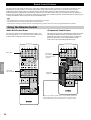
Opening and Closing the Front Panel Door
When you are not operating the controls behind the front panel door, close the door.
%
%
%
%

8
Introduction
ON SCREEN
LEVEL
SLEEP TEST
PARAMETER
SET MENU
%
%
TRANSMIT RE-NAME CLEAR
MACRO
MACROLEARN
OFF ON
SYSTEM
POWER
STANDBY
V-AUX TAPE PHONO
D-TV CBL/SAT TUNER MD CD
VCR 1 VCR 2 VCR 3 LD DVD
6CH INPUT
TITLE
ENTER
MENU
SOUND
DISPLAY
SOURCE
SELECT
SEARCH CHAPTER
%
!
!
$
*#
$
%
%
%
%
%
10KEY DSP HALL 1 HALL 2 CHURCH JAZZ CLUB
ROCK
CONCERT
ENTER-
TAINMENT
CONCERT
VIDEO 2
CONCERT
VIDEO 1
POWER REC STOP PAUSE PLAY
6.1/ES
TV
THEATER
MOVIE
THEATER 2
MOVIE
THEATER 1
/DTS
SUR.
0 +10 +100
1234
5678
9101112
++ +
TV VOL
A / B / C / D / E PRESET
TV INPUT
TV MUTE
CH
DISC
MUTE
EFFECT
VOLUME
+–
/
CHP/INDEX
–– –
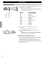
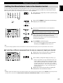
Controls and Functions
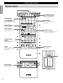
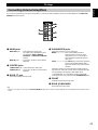
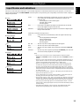
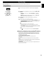
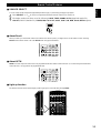
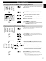
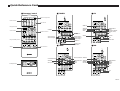
Remote Control
Power Buttons
Turn the power on and off.
Press SYSTEM POWER to turn on the
power and STANDBY to turn off
(Standby mode) the power to the main
unit.
Display Window
Shows the source component
that you select to control.
Program/10-Key
Section
Functions as the numeric buttons or DSP
program group buttons.
Source Select
Selects the source component
without switching the input.
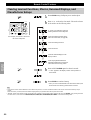
Setup Section
Sets speaker output levels, SET
MENU, DSP parameters, etc.
Others
Functions vary depending on your
components that are set up with the
manufacturer code.
Programming Section
Provides a selection of programming
types you can utilize to conveniently
operate your other components.
Input Section
Selects the input source.
Press an input button repeatedly to select
the input mode.
Operation Section
Provides functions such as play, stop, skip, etc.
for operating your other components.
Volume Section
Controls the volume.

9
English
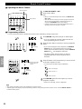
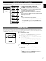
~ Infrared window
Outputs infrared control signals. Aim this window at the
component you want to operate.
Ÿ CLEAR
Used for clearing functions acquired using the Learn and
Rename features, programmed macros, and preset
manufacturer codes (see pages 65, 66).
! RE-NAME
Used for changing the source name in the display window (see
page 65).
⁄ LEARN
Used for setting up the manufacturer code or programming the
functions of other remote controls (see pages 61, 62).
@ MACRO
Used to program a series of operations onto a single button
(see page 63).
¤ MACRO ON/OFF
Turns the macro function on and off.
# TRANSMIT
Flashes while the remote control is sending signals.
‹ 6CH INPUT
Switches to the 6CH INPUT mode when using an external
decoder.
$ LIGHT
Turns the light on or off.
When you press this button once, the light turns on for about
ten seconds. Press again to turn off the light.
› 10KEY/DSP
Selects the numeric button (10KEY) mode or DSP mode. You
can use the 13 buttons to select numbers or DSP programs
directly according to the position of this switch.
% DSP program group/Numeric buttons
Select DSP programs or numbers according to the position of
10KEY/DSP. (Press a button repeatedly to select a DSP
program within that group.)
fi A/B/C/D/E
Selects one of the five preset station groups.
TV operation buttons
TV INPUT switches between TV and VCR mode.
TV MUTE mutes the TV sound.
^ TV VOL +/–
Increases or decreases the TV volume level.
Controls and Functions
fl +/–
PRESET +/– selects a preset station.
CH +/– selects the next or previous channel.
DISC +/– skips to the next or previous disc.
& MUTE
Mutes the sound. Press again to restore audio output at the
previous volume level.
‡ VOLUME +/–
Increases or decreases the volume level.
* EFFECT
Switches the effect speakers (center, front, rear, and rear
center) on and off. If the output of these speakers is switched
off, all DTS and Dolby Digital audio signals are directed to the
main left and right channels except for the LFE channel.
° Cover
Slides down to show the setup buttons.
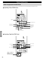
( LEVEL
Selects the effect speaker channels (center, front, rear and
subwoofer) so you can adjust their level independently. Press
this button repeatedly to select the effect speaker channel you
want to adjust, then use + or – to adjust the level.
· ON SCREEN
Selects the On-Screen Display mode for your video monitor.
) SLEEP Timer
Sets the Sleep Timer. Press repeatedly to set the amount of
time before the main unit is automatically turned off.
‚ TEST
Selects the test mode (see page 27).
_ PARAMETER/SET MENU
Selects the PARAMETER mode or SET MENU mode.
You can use the cursor
%
/
%
/ + / – buttons to adjust DSP
program parameter values or SET MENU items according to
the position of this switch.
— Cursor buttons
%
/
%
/ + / –
Selects and adjusts DSP program parameters and SET MENU
items according to the position of PARAMETER/SET
MENU.
+ RESET
Press this button after you exchange batteries or when the
remote control stops working properly. (Pressing RESET does
not clear acquired functions.)

10
Introduction
Controls and Functions
Front Panel Display
DIGITAL
DSP
PCM
PRO LOGIC
SPEAKERS
AB
LD
D-TV
CBL/SAT
VCR 1
VCR 2
VCR 3
V-AUX
DVD
MD
TAPE
TUNER
CD
PHONO
VIRTUAL
SLEEP
STEREO
AUTO
TUNING
MEMORY
~ DTS indicator
Lights up when the built-in DTS decoder is on.
Ÿ VIRTUAL indicator
Lights up when using Virtual Cinema DSP (See page 34.)
! Multi-information display
Shows the current DSP program and other information when
adjusting or changing settings.
⁄ STEREO indicator
Lights up when the AUTO TUNING indicator is on and the
unit is receiving a strong signal for an FM stereo broadcast.
@ Input source indicator
Shows the current input source with the arrow-shaped cursor.
¤ DIGITAL and PRO LOGIC
indicators
Light up according to the type of Dolby signals this unit is
reproducing.
“
DIGITAL” lights up when the built-in Dolby Digital
decoder is on.
“
PRO LOGIC” lights up when the built-in Dolby Pro
Logic Decoder is on.
# DSP indicator
Lights up when you select a digital sound field program.
‹ Headphones indicator
Lights up when headphones are connected.
$ SPEAKERS A/B indicator
Lights up according to which set of main speakers are selected.
Both indicators light up when both sets of speakers are selected.
› PCM indicator
Lights up when this unit is reproducing PCM (Pulse Code
Modulation) digital audio signals.
% AUTO TUNING indicator
Shows that the Tuner is in automatic tuning mode.
fi MEMORY indicator
Flashes to show a station can be saved.
^ SLEEP indicator
Lights up while the Sleep Timer is on.

11
English
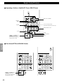
Controls and Functions
~ RF (AC-3) input jack
Connect to the RF output terminal of your LD player.
Ÿ Audio equipment jacks
Refer to page 16 for hookup information.
! Video equipment jacks
Refer to page 18 for hookup information.
⁄ Antenna input terminals
Refer to page 25 for hookup information.
@ Speaker terminals
Refer to page 20 for hookup information.
¤ AC OUTLETS
Use these outlets to supply power to your other audio/video
equipment.
# AC power cord
Connect to a power outlet.
‹ IMPEDANCE SELECTOR
Use this switch to match the amplifier output to your speaker
impedance. Turn off the power before you change the setting
of this switch (see page 22).
$ DIGITAL OPTICAL/COAXIAL jacks
Refer to page 15 for detailed information.
› 6CH INPUT jacks
Refer to page 24 for hookup information.
% ZONE 2 OUT/VIDEO OUT jacks
Refer to page 68 for hookup information.
fi REMOTE 1 IN/OUT/REMOTE 2 IN
jacks
Refer to page 68 for hookup information.
^ RS232C/CTRL OUT +5V terminals
These are control expansion terminals for commercial use.
Consult your dealer for details.
fl PRE OUT/MAIN IN jacks
Refer to page 23 for hookup information.
Rear Panel

12
Preparations
Preparations
Speaker System Configurations 13
Eight or Seven Speaker Configuration –Full Cinema DSP– ............................ 13
Six Speaker Configuration –Hi Fi DSP– .......................................................... 13
Five Speaker Configuration –Standard 5.1 Channel–....................................... 13
Four Speaker Configuration –Minimum Requirement– ................................... 13
Speaker Placement 14
Placing the Main Speakers ................................................................................ 14
Placing the Center Speaker ............................................................................... 14
Placing the Front Effect, Rear and Rear Center Speakers ................................ 14
When You Use a Projection Screen .................................................................. 14
Placing the Subwoofers..................................................................................... 14
Hookups 15
Connecting to Digital Jacks .............................................................................. 15
About the Video Jacks ...................................................................................... 15
About the RF (AC-3) Signal Input Jack ...................................................... 15
Connecting Audio Components ........................................................................ 16
Connecting Video Components ........................................................................ 18
Connecting Speakers......................................................................................... 20
Connecting External Amplifiers ....................................................................... 23
Connecting an External Decoder ...................................................................... 24
Connecting Power Supply Cords ...................................................................... 24
Connecting the Antennas .................................................................................. 25
On-Screen Displays (OSD) 26
OSD Modes....................................................................................................... 26
Selecting the OSD Mode .................................................................................. 26
Speaker Settings 27
Before You Begin ............................................................................................. 27
Speaker Output Levels 27
Dolby Surround Test......................................................................................... 28
DSP Test ........................................................................................................... 29

13
English
Front Effect Speakers Rear Speakers
Front Subwoofer
Rear Center Speaker
Rear Subwoofer
( )
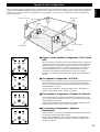
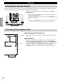
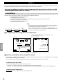
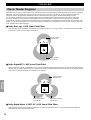
Speaker System Configurations
The most complete speaker configuration consists of eight speakers: the left and right Main speakers, a Center speaker, the left and right Rear
speakers, the left and right Front Effect speakers, and a Rear Center speaker. If you do not use eight speakers, you can direct the signals for
speakers that are not in your system to other speakers in your configuration. A Subwoofer can be used with any of these configurations to
produce a fuller sound.
Front Effect Speakers
Front Subwoofer
Center Speaker
Main Speakers
Rear Speakers
Rear Center Speaker
Rear Subwoofer
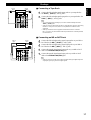
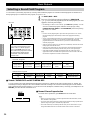
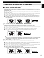
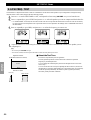
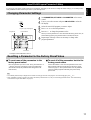
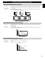
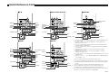
■ Eight or Seven Speaker Configuration –Full Cinema
DSP–
When you reproduce feature film software, this configuration fullly expresses the
powerful and realistic sound qualities of 70 mm multitrack audio. The dialogue is
positioned as if it were coming from directly on the screen, the sound effect is
positioned slightlly behind the screen, and the soundtrack music is positioned
even further behind the screen to express the width and depth of the overall
presentation. This configuration makes the most of this unit’s capability.
The Rear Center speaker is useful for playback of Dolby Digital Surround EX or
DTS ES.
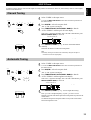
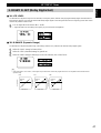
■ Six Speaker Configuration –Hi Fi DSP–
This configuration is used the most for audio playback with HiFi DSP. It does not
position the dialogue sound as well as a seven or eight speaker configuration.
However, it creates a dynamic DSP (Digital Sound Field Processor) sound field
which adds depth to the sound.
For this speaker configuration, change SET MENU item 1A. CENTER SP to
“NONE” and 1D. REAR CT SP to “NONE” (see page 41).
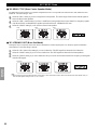
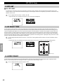
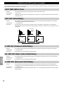
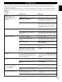
■ Five Speaker Configuration –Standard 5.1 Channel–
This configuration does not express the height of the sound field as well as the
seven or eight speaker configuration. However, it positions the dialogue sound as
coming directly from the screen.
For this speaker configuration, change SET MENU item 1F. FRNT EFCT SP to
“NONE” and 1D. REAR CT SP to “NONE” (see page 41).
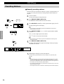
■ Four Speaker Configuration –Minimum
Requirement–
In this configuration, the Center speaker signals and Front Effect speaker signals
are directed to the left and right Main speakers.
For this speaker configuration, change SET MENU item 1A. CENTER SP to
“NONE,” item 1F. FRNT EFCT SP to “NONE,” and item 1D. REAR CT SP to
“NONE” (see page 41).

14
Preparations
Front Effect Speakers
Rear Speakers
Front Subwoofer
Rear Center Speaker
Rear Subwoofer
FL
L
approx.
1m
approx.
1m
0.5~1m 0.5~1m1.5~3m
RL
CR
FR
RR
RC
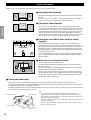
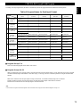
Speaker Placement
Where you place your speakers has a tremendous effect on how well your system sounds.
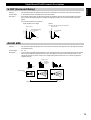
■ Placing the Main Speakers
Place the left and right Main speakers an equal distance from the main listening
position.
If you have a TV or video monitor in your system, the distance of each speaker
from each side of the TV or video monitor should be the same.
■ Placing the Center Speaker
If you have a TV or video monitor in your system, align the front face of the
Center speaker with the front face of the monitor. Place the speaker as close to the
monitor as possible, such as directly over or under the monitor. If you place the
speaker under the monitor, the Front Effect speakers can adjust the height of the
sound to correspond with the action on the screen (depending on the listener’s
position). If you have a projection screen in your system, place the Center speaker
under the screen. Be sure to align the speaker with the center of the screen.
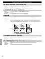
■ Placing the Front Effect, Rear and Rear Center
Speakers
These speakers should be placed about 0.5~1m (1~3 feet) outside the Main
speakers and in the front of the room. They should be turned toward the main
listening position. Place the Rear speakers in the back of the room so they face the
main listening position. The Rear speakers can be placed farther apart than the
Front Effect speakers. The Front Effect and Rear speakers should be placed about
1.8m (6 feet) above the floor.
Once you begin listening to programs, continue to adjust the speaker placement
until you obtain a balanced sound from the Main speakers and the Front Effect
and Rear speakers.
■ When You Use a Projection Screen
Place the speakers as shown in the illustration.
The Main speakers should be placed about one-quarter of the way up from the
bottom of the screen.
Place the Center speaker in the center and directly under the screen. The Center
speaker provides precise dialogue localization.
When you use a projection screen with your system, the Front Effect speakers
provide better effect quality. The CINEMA-DSP sound field programs (see page
34) raise the sound from the Center speaker upward and provide natural sound
corresponding with the video images.
■ Placing the Subwoofers
Place the Front Subwoofer near the Main speakers. Turn it slightly toward the center of the room to reduce wall reflections.
If you use a Rear Subwoofer, place it behind the main listening position. The placement of the Rear Subwoofer is not critical because of
the ultralow frequencies of the sound being reproduced.
By adding a high quality Subwoofer to the speaker configurations shown on pages 21 and 22, you can enjoy more powerful and realistic
movie effects, even if your Main speakers are large.
Note:
• If you use different brands of speakers (with different tonal qualities) in your
configuration, the tone of a moving human voice and other types of sound may not
shift smoothly. We recommend that you use speakers from the same manufacturer or
speakers with the same tonal quality.
You can also adjust the output levels and equalization of your effect speakers using the
SET MENU (see page 41).
If you are using small speakers, the addition of a Subwoofer will reinforce the sound
effects of movies (see page 21).
L
C
R
1/4
1
Main
speaker
Main
speaker
TV or Video
monitor
TV or Video
monitor
Center speaker
Front Effect speakers
Front Subwoofer
Rear
Subwoofer
Rear
Center
speaker
Rear speakers
Center
speaker
(3ft) (1~3ft) (5~15ft) (1~3ft) (3ft)
Main speakers

15
English
Hookups
RF(AC-3)
LD
PR/CRPB/CBY
Composite VIDEO terminal
S VIDEO terminal
COMPONENT VIDEO terminals
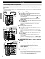
Connecting to Digital Jacks
The RX-V1 has digital jacks for direct transmission of digital signals through either coaxial or fiber optic cables. You can use the digital
jacks to input PCM, DTS and Dolby Digital bitstreams. When you connect components to both the COAXIAL and OPTICAL jacks (for CD,
DVD, and CBL/SAT) priority is given to the input signals from the COAXIAL jack. All digital input jacks are acceptable for 96 kHz/24 bit
digital signals.
■ About the Dust Protection Cap
Pull out the cap from the optical jack before you connect the fiber optic cable. Do
not discard the cap. When you are not using the optical jack, be sure to put the cap
back in place. This cap protects the jack from dust.
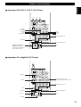
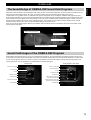
About the Video Jacks
There are three types of video jacks. Video signals input through the VIDEO jacks are the conventional composite video signals. Video
signals input through the S VIDEO jacks are separated into luminance (Y) and color (C) video signals. The S-video signals achieve high
quality color reproduction.
Video signals input through the COMPONENT VIDEO jacks are separated into luminance (Y) and color difference (PB/CB, PR/CR) video
signals. The jacks are also separated into three for each signal. The description of the component video jacks may be different depending on
the component (e.g. Y, CB, CR / Y, PB, PR / Y, B-Y, R-Y/ etc.). Component video signals provide the best quality in picture reproduction.
Note:
• Each type of video jack works independently. Signals input through the composite
video, S-video, and component jacks are output through the corresponding composite
video, S-video, and component jacks respectively.
Caution:
• Use a commercially available S-video cable when connecting to the S VIDEO jacks,
and commercially available video cables when connecting to the COMPONENT
VIDEO jacks.
• When you are using the COMPONENT VIDEO jacks, check the details in the owner’s
manual that came with the component being connected.
About the RF (AC-3) Signal Input Jack
If your LD player has an RF (AC-3) signal output jack, connect it to the RF (AC-3) input jack on this unit. If RF (AC-3) and analog
signals are input at the same time, priority is given to the RF signals. When you want to reproduce RF (AC-3) signals, set the input mode
to “D.D. RF” using INPUT MODE.
Note:
• RF (AC-3) signals cannot be output using the REC OUT selector. When you record
sound or images from an LD player, be sure to connect the player to either the
DIGITAL OPTICAL or analog AUDIO jacks.
Caution:
• Even if you connect an LD player with an RF (AC-3) output jack to this unit, you
cannot reproduce Dolby Digital sound from all LD discs. You must playback an LD
disc encoded with Dolby Digital signals in order to take advantage of the Dolby Digital
sound.

16
Preparations
Hookups
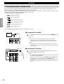
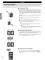
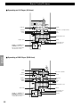
Connecting Audio Components
Before you connect any components, disconnect the power supply to all the components you plan to connect including the RX-V1 and
determine which jacks are for the left and right channels and for input and output.
When you connect other YAMAHA audio equipment (such as a CD player or changer, MD deck, or tape deck, connect to terminals with the
same number labels. Yamaha applies this labelling system to all its products.
In the hookup illustrations on the following pages:
indicates signal direction,
indicates coaxial cables,
indicates left side analog cables,
indicates right side analog cables,
indicates optical cables; and,
indicates S-video cables.
After you finish all hookups, check them again to make sure they are correct.
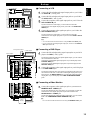
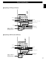
■ Connecting a Turntable
1
1
Connect the left and right signal output cords to the PHONO L and
R jacks.
Note:
• These jacks are for connecting a turntable with an MM or high output MC
cartridge. If you have a turntable with a low output MC cartridge, use an inline
boosting transformer or MC-head amplifier when connecting to these jacks.
Caution:
• The GND terminal does not electrically ground the turntable. It simply reduces
noise in the signal. In some cases, you may hear less noise if you do not connect to
the GND terminal.
■ Connecting a CD Player
1
1
Connect the left and right analog signal output jacks on your CD
player to the CD 1 L and R jacks.
Notes:
• The COAXIAL CD and OPTICAL CD jacks are available for a CD player which
has coaxial or optical digital outputs.
• When you connect a CD player to both the COAXIAL CD and OPTICAL CD
jacks, priority is given to the input signals from the COAXIAL CD jack.
• The OPTICAL jacks on this unit conform to the EIA standard. If you use a fiber
optic cable that does not conform to this standard, the RX-V1 may not function
properly.
C
O
S
L
R
IN
CD
GND
DVD
VIDEO
LD
D-TV
CBL
CD
DVD
LD
CBL
AUDIO
PHONO
AUDIO VIDEO
S VIDEO
RF(AC-3)
L
R
MAIN
IN
(PLAY)
IN
(PLAY)
CD
GND
TAPE
OUT
(REC)
OUT
(REC)
MD
VCR 1
VCR 2
DVD
VIDEO
LD
D-TV
CBL
/SAT
IN
IN
IN
OUT
OUT
CD
CD
DVD
DVD
LD
MD
OUT
(REC)
IN
(
PLAY)
CBL
/SAT
AUDIO
PHONO
AUDIO VIDEO
S VIDEO
COMPONE
N
Y
OU
T
REMOTE 1
COAXIAL
OPTICAL
RF(AC-3)
A
B
C
O
C
L
R
Turnable
Output
Ground
Optical Output
Coaxial Output
Analog Output
CD player
Sidan laddas...
Sidan laddas...
Sidan laddas...
Sidan laddas...
Sidan laddas...
Sidan laddas...
Sidan laddas...
Sidan laddas...
Sidan laddas...
Sidan laddas...
Sidan laddas...
Sidan laddas...
Sidan laddas...
Sidan laddas...
Sidan laddas...
Sidan laddas...
Sidan laddas...
Sidan laddas...
Sidan laddas...
Sidan laddas...
Sidan laddas...
Sidan laddas...
Sidan laddas...
Sidan laddas...
Sidan laddas...
Sidan laddas...
Sidan laddas...
Sidan laddas...
Sidan laddas...
Sidan laddas...
Sidan laddas...
Sidan laddas...
Sidan laddas...
Sidan laddas...
Sidan laddas...
Sidan laddas...
Sidan laddas...
Sidan laddas...
Sidan laddas...
Sidan laddas...
Sidan laddas...
Sidan laddas...
Sidan laddas...
Sidan laddas...
Sidan laddas...
Sidan laddas...
Sidan laddas...
Sidan laddas...
Sidan laddas...
Sidan laddas...
Sidan laddas...
Sidan laddas...
Sidan laddas...
Sidan laddas...
Sidan laddas...
Sidan laddas...
Sidan laddas...
Sidan laddas...
Sidan laddas...
Sidan laddas...
Sidan laddas...
Sidan laddas...
Sidan laddas...
Sidan laddas...
Sidan laddas...
Sidan laddas...
Sidan laddas...
Sidan laddas...
Sidan laddas...
Sidan laddas...
Sidan laddas...
Sidan laddas...
Sidan laddas...
Sidan laddas...
Sidan laddas...
-
 1
1
-
 2
2
-
 3
3
-
 4
4
-
 5
5
-
 6
6
-
 7
7
-
 8
8
-
 9
9
-
 10
10
-
 11
11
-
 12
12
-
 13
13
-
 14
14
-
 15
15
-
 16
16
-
 17
17
-
 18
18
-
 19
19
-
 20
20
-
 21
21
-
 22
22
-
 23
23
-
 24
24
-
 25
25
-
 26
26
-
 27
27
-
 28
28
-
 29
29
-
 30
30
-
 31
31
-
 32
32
-
 33
33
-
 34
34
-
 35
35
-
 36
36
-
 37
37
-
 38
38
-
 39
39
-
 40
40
-
 41
41
-
 42
42
-
 43
43
-
 44
44
-
 45
45
-
 46
46
-
 47
47
-
 48
48
-
 49
49
-
 50
50
-
 51
51
-
 52
52
-
 53
53
-
 54
54
-
 55
55
-
 56
56
-
 57
57
-
 58
58
-
 59
59
-
 60
60
-
 61
61
-
 62
62
-
 63
63
-
 64
64
-
 65
65
-
 66
66
-
 67
67
-
 68
68
-
 69
69
-
 70
70
-
 71
71
-
 72
72
-
 73
73
-
 74
74
-
 75
75
-
 76
76
-
 77
77
-
 78
78
-
 79
79
-
 80
80
-
 81
81
-
 82
82
-
 83
83
-
 84
84
-
 85
85
-
 86
86
-
 87
87
-
 88
88
-
 89
89
-
 90
90
-
 91
91
-
 92
92
-
 93
93
-
 94
94
-
 95
95


på andra språk
- italiano: Yamaha RX-V1 Manuale utente
- čeština: Yamaha RX-V1 Uživatelský manuál
- español: Yamaha RX-V1 Manual de usuario
- Deutsch: Yamaha RX-V1 Benutzerhandbuch
- polski: Yamaha RX-V1 Instrukcja obsługi
- português: Yamaha RX-V1 Manual do usuário
- français: Yamaha RX-V1 Manuel utilisateur
- Türkçe: Yamaha RX-V1 Kullanım kılavuzu
- English: Yamaha RX-V1 User manual
- dansk: Yamaha RX-V1 Brugermanual
- русский: Yamaha RX-V1 Руководство пользователя
- suomi: Yamaha RX-V1 Ohjekirja
- Nederlands: Yamaha RX-V1 Handleiding
- română: Yamaha RX-V1 Manual de utilizare
Relaterade papper
-
Yamaha RX-V3000 Användarmanual
-
-
-
-
Yamaha HTR-5590 Bruksanvisning
-
-
-
-
-
Yamaha DSP-E800 Bruksanvisning
Andra dokument
-
Sony TA-VA80ES Användarmanual
-
-
Sony STR DE 585 Bruksanvisning
-
-
Sony STR DE-445 & STR-DE445,MV Bruksanvisning
-
-
Sony STR-DE375 Användarmanual
-
-
Sony STR-DB830 Användarmanual
-