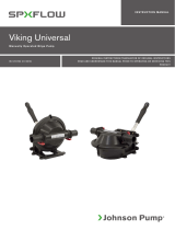
SPX FLOW Viking Power Waste Water Pump Användarmanual
- Typ
- Användarmanual

INSTRUCTION MANUAL
ORIGINAL INSTRUCTIONS/TRANSLATION OF ORIGINAL INSTRUCTIONS
READ AND UNDERSTAND THIS MANUAL PRIOR TO OPERATING OR SERVICING THIS
PRODUCT
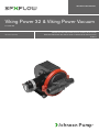
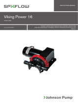
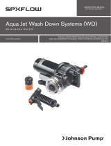
Viking Power 32 & Viking Power Vacuum
12/24 V DC
IB-117 R05 (09/2017)

Recreational Craft Directive 94/25/EEC
ISO8849: 2003 Electrically operated bilge pumps
ISO 8846: 1990/Electrical devices -
Protection against ignition of surrounding flammable gases
EN ISO 10133: 2001/Electrical systems - Extra low-voltage DC installations
Electromagnetic Compatibility Directive 89/336/EEC
EN55014: 2000/Radio Disturbance
Garanti 3 år
Warranty 3 years
Garantie 3 Jahren
Garantie 3 ans
Garantía 3 años
Garanzia 3 anni
INDEX INDICE
Svenska ..................................................................................................................... 3
English ...................................................................................................................... 7
Deutsch .................................................................................................................. 11
Français .................................................................................................................. 15
Español ................................................................................................................... 19
Italiano .................................................................................................................... 23
SE: Besök www.spxflow.com för mer information om vår världsomspännande organisation, våra godkännanden, certifieringar och
lokala representanter. SPX FLOW, Inc. förbehåller sig rätten att ändra design och material utan föregående avisering. Designelement,
konstruktionsmaterial och dimensioner som beskrivs i denna bulletin gäller endast som information och skall alltid bekräftas skriftligt för att
vara gällande.
EN: For more information about our worldwide locations, approvals, certifications, and local representatives, please visit www.spxflow.
com. SPX FLOW, Inc. reserves the right to incorporate our latest design and material changes without notice or obligation. Design
features, materials of construction and dimensional data, as described in this bulletin,
are provided for your information only and should not be relied upon unless confirmed in writing.
DE: Für weitere Informationen über unsere weltweiten Standorte, Zulassungen, Zertifizierungen und unsere Vertreter vor Ort, besuchen
Sie bitte unsere Webseite: www.spxflow.com. Die SPX FLOW, Inc. behält sich das Recht vor, die neuesten Konstruktions- und
Werkstoffänderungen ohne vorherige Ankündigung und ohne Verpflichtung hierzu einfließen zu lassen. Konstruktive Ausgestaltungen,
Werkstoffe sowie Maßangaben, wie sie in dieser Mitteilung beschrieben sind, sind nur zur Information. Alle Angaben sind unverbindlich,
es sei denn, sie wurden schriftlich bestätigt.
FR: Pour plus d’information sur nos succursales internationales, nos approbations, nos certifications et nos représentants locaux, veuillez
consulter notre site Internet au www.spxflow.com. SPX FLOW, Inc. se réserve le droit d’incorporer nos plus récents concepts ainsi
que tout autre modification importante sans préavis ou obligation. Les éléments décoratifs, matériaux de construction et les données
dimensionnelles, tels qu’énoncés dans ce communiqué, sont fournis pour votre information seulement et ne doivent pas être considérés
comme officiels à moins d’avis contraire par écrit.
ES: Para más información sobre nuestras oficinas a nivel mundial, aprobaciones, certificaciones y representantes locales, por favor visite
www.spxflow.com. SPX FLOW, Inc. se reserva el derecho de incorporar nuestro diseño más reciente y cambios materiales sin necesidad
de notificación previa u obligación de ningún tipo. Características de diseño, materiales de construcción y dimensiones, tal y como están
descritas en este boletín, son proporcionadas sólo con fines informativos y no deben ser usados como referencia a menos que sean
confirmados por escrito.
IT: Per ottenere maggiori informazioni sulle nostre sedi nel mondo, autorizzazioni, certificazioni, e rappresentanti locali, potete visitare
il sito www.spxflow.com. La SPX FLOW, Inc. si riserva il diritto di apportare cambiamenti ai propri design e materiali senza preavviso o
vincolo. Le caratteristiche del design, i materiali di costruzione e i dati dimensionali, così come descritti nel presente bollettino, sono
forniti solo per vostra informazione e non saranno oggetto di obbligazione salvo autorizzazione confermata per iscritto.

Typiska användningsområden
Viking Power 32/Vakuum är en membranpump
och det perfekta valet för toalettläns,
länspumpning och avfallsvatten. Den kompakta
designen gör att den kan installeras i stort sett
var som helst efter avloppet för svartvatten
eller som länspump. Viking Power Vakuum har
större självsugningsförmåga, och är speciellt
lämplig att installeras i ett vakuumsystem.
Modeller
Viking Power 32 12V 10-13373-03
Viking Power 32 24V 10-13373-04
Viking Power Vakuum 12V 10-13373-07
(Dubbla backventiler)
Viking Power Vakuum 24V 10-13373-08
(Dubbla backventiler)
Egenskaper
• 32 L/min öppet flöde – Viking Power 32
• 30 L/min vid 0.1 bar – Viking Power 32
• 24 L/min öppet flöde – Viking Power
Vakuum
• 22 L/min vid 0.1 bar – Viking Power
Vakuum
• Kompakt design
• Anslutning 1½” slang (Ø 38 mm)
• Tystgående
• Självsugande upp till 2,5 m –
Viking Power 32
• Självsugande upp till 5 m – Viking Power
Vakuum
• Pumphuvudet kan rotera 360°
• Kan torrköras
• Inget filter behövs
• Kullagerstödd kraftöverföring
• Låg strömförbrukning (40 W vid 0,1 bar)
• Kan även handvevas
• Uppfyller ISO15083 (Small Craft Bilge
Pump standard for boats from 12 m/40 ft)
Funktionsprincip
Enkammars sjävsugande membranpump.
För att uppnå god självsugande förmåga
för en filterlös pump, är pumpen designad
med ett stort membran och ett långt slag.
På detta sätt spolas mycket vatten genom
pumphuset vid varje slag och på så sätt
spolas smutspartiklar bort (jfr slaskrensare
av gummi).
Teknisk beskrivning
Pumphus och
vevhus: Nylon
Ventiler: Nitril
Membran: Armerad nitril
Skruvar: Rostfritt stål
Fot: Målad galvaniserad plåt
Anslutning: 1½” slang
Max. utloppshöjd: 4 m
Max. lyft höjd: 2,5 resp. 5 m
Max höjd+lyft: 5 m
Motor: 40 W vid 0,1 bar
12/24 V
(Inbyggt termoskydd)
Säkring: 12 A – 12V /
6 A – 24V
Pumpen är CE-märkt enl följande standarder:
• EN55014-1:2000/Radiostörningar
• ISO8846: Båtar – Elkomponenter –
Skydd mot antändning av omgivande
brännbara gaser
• ISO8849:2003/Båtar – Elektriska
länspumpar
• ISO10133:2001/Båtar – Elektriska
system – Klenspänningsinstallationer för
likström
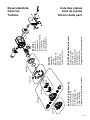
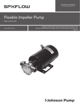
Sprängskiss
Se sidan 27
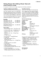
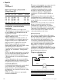
Viking Power 32 & Viking Power Vacuum
med 12/24 V motor
Läs igenom installationsanvisningen noga innan montering av pumpen.
3
Översättning av originalinstruktionerna
> Svenska

Tryck- och kapacitetsdata
Tryck Flöde Ampere
Bar kPa Psi l/min USGPM 12V 24V
0 0 0 34.4 9.1 2.5 1.2
0.1 10 1.5 30.8 8.1 3.3 1.6
0.2 20 2.9 27.1 7.2 4.2 2.1
0.3 30 4.4 23.5 6.2 5.0 2.5
0.4 40 5.8 20.0 5.3 5.6 2.8
0.5 50 7.2 16.7 4.4 6.1 3.1
Erforderlig säkring 12 A 6 A
Installation och skötsel
Installation
• Montera pumpen i ett torrt utrymme.
• Om pumpen monteras vertikalt ska
motorn vara ovanför pumphuset.
• Märk ut skruvhålen och borra styrhål.
• Montera pumpen med rostfria skruvar,
tillsammans med de bifogade brickorna.
Kontrollera att plasthylsorna är rätt
placerade. OBS! Dra inte åt de vibra-
tionsdämpande gummifötterna för hårt.
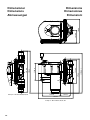
• Montera de yttre backventilerna och
skruva på anslutningarna – Viking
Power Vakuum.
OBS! Backventilerna monteras med den
spetsiga ändan i flödesriktningen. Se
sprängskiss.
• Armerad, böjlig slang rekommenderas.
• Använd rostfria slangklämmor för att
fästa slangarna på anslutningarna och
andra slangar i systemet.
Elektrisk installation
Pumpen ska installeras i enlighet med
ISO 10133 (Båtar - Elektriska system -
klenspänningsinstalltioner för likström)
OBS! Säkringen ska vara av gnistskyddad
typ. Motorn har ett termiskt
överbelastningsskydd som skyddar motorn
från överhettning. Skyddet återställs
automatiskt när motorn svalnat. Se
kopplingsschema för rätt installation.
Negativ ledare ska vara svart.
Välj kabeldimension efter total kabellängd
(se tabell). Kabelanslutningarna skall avtätas
med ett marint tätningsmedel.
Obs! Kontrollera före installation med
elektriska styrsystem att utrustningen som
ska användas har tillräcklig effekt för motorns
strömstyrka. Låg spänning kan medföra att
motorn överhettas.
Underhåll och skötsel
Ventilerna i pumphuset skall rengöras
regelbundet för att undvika reducerad
pumpeffekt och dålig självsugningsförmåga.
Detta görs genom att skruva loss klämmorna
till pumphuset och öppna
huset. Dom yttre backventilerna sitter innanför
anslutningarna. (Viking Power Vakuum.) OBS!
Se till att strömmen är bruten då detta görs.
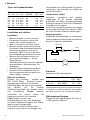
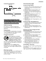
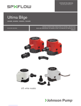
Kopplingsschema
Andra elektriska anordningar, t.ex. strömbrytare,
reläer ska placeras mellan pump och batteriets
pluspol (+) (på den röda kabeln).
Pump
Säkring
Max 0.2 m
Röd
Svart
+
–
Kabelarea
(baserat på 10% spänningsfall)
Kabelarea Max kabel längd* i m
12V 24V
1.5 mm² #16 AWG 18 71
2.5 mm² #14 AWG 30 118
* Kabellängden är det totala avståndet från batteriet
till pumpen och tillbaka till batteriet. Använd gärna
ett relä för att korta av de strömförande ledarna.
Självsugningsförmåga
Pumpen är självsugande upp till 2,5 resp. 5
m (Viking Power Vakuum)
4Översättning av originalinstruktionerna
> Svenska

Torrkörning
Pumpen kan torrköras utan att ta skada.
Det kommer dock att i längden reducera
batteriets kapacitet.
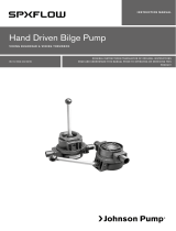
Handvevsdrift
Pumpen kan, i ett nödläge med
strömavbrott, handvevas med
den bifogade veven.
OBS! Se till att strömmen är
bruten då detta görs, då motorn
i detta fall fungerar som generator.
OBS! Kör aldrig pumpen med
strömförsörjning när veven är monterad!
Vinterförhållanden
Töm pumpen på vatten genom att pumpa
tills den suger luft och ingen vätska kommer
från utloppet.
Serviceinstruktioner
Byte av membran
1. Ta bort de två skruvarna som håller
klämmorna och ta bort dem.
2. Ta bort pumphuset.
3. Ta bort skruven som håller membranet
och membranbrickan.
4. Ta bort membranet och membran
brickan.
5. Montera det nya membranet och den nya
membranbrickan med den nya skruven.
6. Montera pumphuset och klämmorna.
Byte av pumphus
1. Ta bort de två skruvarna som håller
klämmorna och ta bort dem.
2. Ta bort pumphuset.
3. Montera det nya pumphuset och
klämmorna.
Rengöring av backventilen/
backventilerna
1. Ta bort de två skruvarna som håller
klämmorna och ta bort dem
2. Ta bort pumphuset
3. Inspektera gummibackventilen och ta
bort ev. skräp/smuts.
4. Skruva bort anslutningarna och inspek-
tera de yttre backventilerna. (Viking
Power Vakuum.)
5. Montera anslutningarna, pumphuset och
klämmorna.
Avfallshantering/Materialåtervinning
Vid avfallshantering skall produkten lämnas
för destruktion/återvinning enligt gällande
lagstiftning. Vid tillämpliga fall demonteras
och sorteras produkten i ingående
materialfraktioner.
5
Översättning av originalinstruktionerna
> Svenska

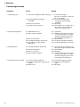
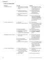
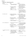
Felsökningsschema
Symptom Orsak Åtgärd
1. Pumpen går inte. 1.1 Utlöst termoskydd eller defekt säkring. 1.1.1 Kontrollera säkringen.
Låt motorn svalna före omstart om
den är överhettad.
1.2 Felaktig kabelanslutning eller 1.2.1 Kontrollera batteriet/ström
strömkälla. försörjning, huvudsäkringen
och kablar.
1.4 Motorn är ur funktion. 1.4.1 Byt pump
1.5 Pumpen/motorn är frusen. 1.5.1 Tina pumpen och systemet, syna
efter skador. Risk för skada vid
start av frusen pump/motor.
2. Pumpen självsuger inte. 2.1 Vattentanken är tom. 2.1.1 Fyll tanken.
2.2 Smuts under/i ventilerna. 2.2.1 Öppna pumpen genom att skruva
loss de två skruvarna och rengör
ventilerna. Rengör de yttre venti-
lerna. (Viking Power Vakuum.)
2.3 Perforerat membran. 2.3.1 Byt membran.
2.4 Läckage på pumpens inloppssida. 2.4.1 Kontrollera slanganslutningarna.
2.5 Igensättning i in- eller utlopps- 2.5.1 Kontrollera ledningar och ventiler.
ledningarna.
3. Lågt flöde/tryck. 3.1 Läckage i pumpens utloppssida. 3.1.1 Kontrollera att anslutningarna är
täta. Syna slangen avseende skada.
3.2 Perforerat membran. 3.2.1 Byt membran.
3.3 Motorn ur funktion. 3.3.1 Byt pump.
3.4 Smuts under/i ventilerna. 3.4.1 Öppna pumpen genom att skruva
loss de två skruvarna och rengör
ventilerna. Rengör de yttre ventil-
erna. (Viking Power Vakuum.)
4. Pumpen låter mer än vanligt. 4.1 In- eller utlopp är begränsat. 4.1.1 Kontrollera slang/rörsystemet.
4.2 Utlopp är begränsat/för högt tryck på 4.2.1 Kontrollera att ventilerna är
pumpen öppna.
4.3 Defekt motor. 4.3.1 Byt pump.
6Översättning av originalinstruktionerna
> Svenska

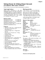
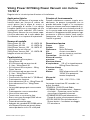
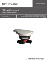
Typical applications
Viking Power 32/Vacuum is the ideal
diaphragm pump for toilet drain, wastewater
and bilge pumping. Its compact design gives
a very adaptable mounting and installation in
the boat. Viking Power Vacuum has a large
self-priming capability and is very suitable
for installation in a vacuum system.
Model number
Viking Power 32 12V 10-13373-03
Viking Power 32 24V 10-13373-04
Viking Power Vacuum 12V 10-13373-07
(double anti-drainback valves)
Viking Power Vacuum 24V 10-13373-08
(double anti-drainback valves)
Features
• 32 L/min at open flow – Viking Power 32
• 30 L/min at 0.1 bar pressure –
Viking Power 32
• 24 L/min at open flow – Viking Power
Vacuum
• 22 L/min at 0.1 bar pressure – Viking
Power Vacuum
• Compact design
• Connection: 1½” hose
• Quiet operation
• Self-priming to 2,5 m – Viking Power 32
• Self-priming to 5 m – Viking Power
Vacuum
• Pump head can be rotated 360°
• Dry running without damage
• No filter required
• Ball-bearing supported transmission
• Low power consumption (40W at 0.1 bar
pressure)
• Hand-cranked
• Meets ISO15083 (Small Craft Bilge
Pump standard for boats from 12 m/40 ft
Working principle
Single-chamber, self-priming diaphragm
pump. To obtain good self-priming ability
and a filter-less solution, the pump is
designed with a large single diaphragm
and a long stroke. This way a lot of water
is pushed through the pump house in each
stroke and any debris is flushed through
(compare rubber sink cleaner)
Technical description
Body: Nylon
Valves: Nitrile
Diaphragm: Reinforced Nitrile
Screws: Stainless steel
Stand: Painted galvanized steel
Connection: 1½” hose
Max. discharge
height: 4 m
Max. suction lift: 2,5 and 5 m
respectively (Viking Power Vacuum)
Max
discharge+ lift: 5 m
Motor: 40 W at 0.1 bar pressure
12/24V (with built-in
thermal protection)
Fuse size: 12A – 12V / 6 A – 24V
The pump is CE marked according to the
following standards:
• EN55014-1:2000/Radio disturbance
• ISO8846: Small Craft – Electrical devices
– Protection against ignition of surrounding
flammable gases
• ISO8849:2003/ Small craft – Electrically
operated bilge pumps
• ISO10133: 2001/Small Craft – Electrical
systems – Extra-low voltage DC installations
Drawing
See page 27
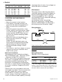
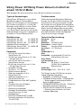
Pressure and Capacity data
Viking Power 32 /Viking Power Vacuum
mounted to DC motor 12/24 V
Please follow all instructions before attempting an installation.
7
Original instructions
> English

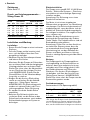
Pressure Flow Amp. draw
Bar kPa Psi L/min USGPM 12V 24V
0 0 0 34.4 9.1 2.5 1.2
0.1 10 1.5 30.8 8.1 3.3 1.6
0.2 20 2.9 27.1 7.2 4.2 2.1
0.3 30 4.4 23.5 6.2 5.0 2.5
0.4 40 5.8 20.0 5.3 5.6 2.8
0.5 50 7.2 16.7 4.4 6.1 3.1
Fuse required 12 A 6 A
Installation and maintenance
Installation
• Mount the pump in a dry location.
• If the pump is mounted vertically, the
motor must be above the pump house.
• Mark screw positions and drill pilot
holes.
• Mount the pump using stainless steel
screws and the enclosed washers. Make
sure that the plastic spacers are in their
correct position. NOTE: Take care not
to fasten the vibration-damping rubber
feet too much.
• Mount the outlet anti-drainback valves
and screw the connections - Viking
Power Vacuum.
NOTE: The anti-drainback valves are
mounted with the pointed end towards
the flow direction. See the drawing.
• Reinforced flexible tubing is recom-
mended.
• Use stainless steel hose clamps to secure
tubing to connections and other hose
barbs in the system.
Electrical installation
The pump must be installed according to
ISO 10133 (Small craft – Electrical system
– Extra low voltage DC installation).
NOTE: The fuse must be ignition protected.
The motor is equipped with built-in thermal
protection to prevent overheating. The
protection is automatically restored when
the motor is cooled. See the wiring diagram
for correct installation. Negative wire must
be black.
Choose wire size in accordance with total
wire length (see table). The wire connections
must be sealed with a marine sealant.
NOTE: Before installation with electrical
control systems, check that equipment to be
used is of sufficient rated capacity to accept
amperage draw of motor. Low voltage can
cause the motor to overheat.
Maintenance
The pump valves inside the pump house
should be regularly cleared from debris to
prevent reduced performance and poor
self priming capability. This is done by
unscrewing the house clamp and opening
the house. The outlet
anti-drainback valves are located
above the connections. (Viking Power
Vacuum.) NOTE: Make sure the pump is
disconnected from the power supply.
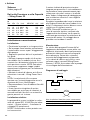
Wiring diagram
Other electrical devices such as circuit breaker
and relays must be installed between the pulp
and the positive (+) lead on the battery (on the
red wire).
Pump
Terminal
fuse
Max 0.2 m
Red
Black
+
–
Wiring dimensions
(Based on 10% voltage drop)
Wire size Max wire length* in m
12V 24V
1.5 mm² #16 AWG 18 71
2.5 mm² #14 AWG 30 118
* The wire length is the total distance from the
battery to the pump and back to the battery. It is
recommended to use a relay with a light wire from
the main cable to shorten the main leaders.
8Original instructions
> English

Self-priming
The pump is self-priming up to 2,5 and 5 m
respectively (Viking Power Vacuum)
Dry running
The pump can be run dry without any harm.
It will however unnecessary reduce your
battery power.
Hand cranked power
The pump can in case of
emergency such as power
failure be run with the enclosed
hand-cranked power source.
NOTE: Make sure that the
pump is disconnected from the
power supply while the motor is working
as a power generator.
NOTE: Do not run the pump with power
supply and the crank mounted at the same
time.
Winterizing
Drain the pump from water by pumping
it until it primes air and there is no fluid
coming from the outlet.
Service instructions
Change of diaphragm
1. Remove the two screws that hold the
clamps and remove the clamps.
2. Remove the pump housing.
3. Remove the screw that holds the
diaphragm and the diaphragm washer.
4. Remove the diaphragm and the
diaphragm washer.
5. Mount the new diaphragm and the new
diaphragm washer with the new screw.
6. Assemble the pump housing and the
clamps.
Change of pump housing
1. Remove the two screws that hold the
clamps and remove the clamps.
2. Remove the pump housing.
3. Assemble the new pump housing and
the clamps.
Cleaning the anti-drainback valve(s)
1. Remove the two screws that hold the
clamps and remove the clamps.
2. Remove the pump housing.
3. Inspect the rubber anti-drainback valve
and remove any debris.
4. Unscrew the connections and inspect
the outlet anti-drainback valves (Viking
Power Vacuum).
5. Assemble the connections, the pump
housing and the clamps.
Waste management / Recycling
Dispose of the product in accordance with
existing regulations.
Where appropriate, dismantle and sort the
product by its material fractions.
9
Original instructions
> English

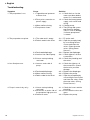
Troubleshooting
Symptom Cause Solution
1. The pump doesn’t run. 1.1 Tripped thermal protector 1.1.1 Check the fuse. Let the
or blown fuse. motor cool down before
restart if it is overheated.
1.2 Faulty wire connection or 1.2.1 Check the battery/power
power supply. supply, main switch and
wiring.
1.4 Motor malfunctioning. 1.4.1 Change pump.
1.5 Pump/motor frozen. 1.5.1 Thaw pump and system
and check for damage.
There is a risk of damage
if a frozen pump/motor
is started.
2. The pump does not prime. 2.1 The water tank is empty. 2.1.1 Fill up the tank.
2.2 Debris under/in the valves. 2.2.1 Open the pump by body
by unscrewing the two
screws and clean the
valves. Clean the outlet
valves. (Viking Power
Vacuum.)
2.3 Perforated diaphragm. 2.3.1 Replace the diaphragm.
2.4 Leak on inlet side of pump. 2.4.1 Check tightness of hose
connections.
2.5 Inlet or outlet plumbing 2.5.1 Check the plumbing and
restricted. the valves.
3. Low flow/pressure. 3.1 Lean on outlet side of 3.1.1 Check the tightness of
pump. the connections. Check
the hose for possible
damage.
3.2 Perforated diaphragm. 3.2.1 Replace the diaphragm.
3.3 Motor malfunctioning. 3.3.1 Replace the pump.
3.4 Debris under/in the valves. 3.4.1 Open the pump body by
unscrewing the two screws
and clean the valves. Clean
the outlet valves. (Viking
Power Vacuum.)
4. Pump is excessively noisy. 4.1 Inlet or outlet plumbing 4.1.1 Check the hoses and the
restricted. plumbing.
4.2 Restriction on outlet side of 4.2.1 Ensure that the valves are
the pump/too high pressure open.
4.3 Defective motor. 4.3.1 Replace the pump.
10 Original instructions
> English

Typische Anwendungen
Viking Power 32/Vacuum ist eine ideale
Membranpumpe für Toilettenabfluss,
Abwasser und Leckwasser. Ihre kompakte
Konstruktion ermöglicht es, sich bei der
Montage und Installation in einem Schiff
sehr gut den Gegebenheiten anzupas-
sen. Viking Power Vacuum hat eine große
Selbstansaugleistung und ist geeignet zur
Installation in einem Vakuumsystem.
Modellnummer
Viking Power 32 12V 10-13373-03
Viking Power 32 24V 10-13373-04
Viking Power Vacuum 12V 10-13373-07
(doppelte Rückschlagventile)
Viking Power Vacuum 24V 10-13373-08
(doppelte Rückschlagventile)
Parameter
• 32 l/min bei freiem Durchfluss –
Viking Power 32
• 30 l/min bei einem Druck von 0,1 bar
– Viking Power 32
• 24 l/min bei freiem Durchfluss –
Viking Power Vacuum
• 22 l/min bei einem Druck von 0,1 bar
– Viking Power Vacuum
• Kompaktes Design
• Anschluss: 1½”-Schlauch
• Geräuscharmer Betrieb
• Selbstansaugend bis 2,5 m –
Viking Power 32
• Selbstansaugend bis 5 m –
Viking Power Vacuum
• Pumpenkopf kann über 360° gedreht
werden
• Trockenlaufen ohne Schaden
• Kein Filter erforderlich
• Getriebe mit Kugellager
• Niedriger Stromverbrauch (40W bei
einem Druck von 0,1 bar)
• Handgekurbelt
• Erfüllt den Standard ISO 15083
(Leckwasserpumpen für Schiffe bis
12 m/40 Fuß)
Funktionsweise
Selbstansaugende Einkammer-Membran-
pumpe. Um ein gutes Selbstansaugen und
eine filterlose Lösung zu erreichen, wurde
die Pumpe mit einer großen Einzelmembran
und einem langen Hub konstruiert. Auf diese
Weise wird eine Menge Wasser bei jedem
Hubvorgang durch die Ventile gedrückt und
alle Schmutzstoffe werden durchgespült
(vrgl. Gummi-Ausgussreiniger).
Technische Beschreibung
Gehäuse: Nylon
Ventile: Nitril
Membran: verstärktes Nitril
Schrauben: rostfreier Stahl
Stand: verzinkter Stahl mit Anstrich
Anschluss: 1½”-Schlauch
Max.
Förderhöhe: 4 m
Max.
Saughöhe: entsprechend 2,5 und 5 m
(Viking Power Vacuum)
Max. Förder-
und Saughöhe: 5 m
Motor: 40 W bei 0,1 bar Druck
12/24V (mit eingebautem
Wärmeschutz)
Größe der
Sicherungen: 12A – 12V / 6 A – 24V
Die Pumpe hat das CE-Zeichen entspre-
chend folgenden Standards:
• EN55014-1:2000/Funkstörung
• ISO8846: Kleine Schiffe – Elektrogeräte
– Schutz gegen Entzündung entflamm-
barer Umgebungsgase
• ISO8849:2003/Kleine Schiffe – Elektrisch
betriebene Leckwasserpumpen
• ISO10133:2001/Elektrische Systeme
– Gleichstrominstallationen mit extra
niedriger Spannung
Viking Power 32/Viking Power Vacuum montiert an
einem 12/24 V-Motor
Bitte befolgen Sie alle Instruktionen, bevor Sie die Installation vornehmen.
11
Übersetzung der Original-Betriebanleitungen
> Deutsch

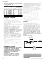
Zeichnung
Siehe Seite 27
Druck- und Leistungsparameter –
Viking Power 32
Druck Durchfluss Stromverbrauch
Bar kPa Psi L/min USGPM 12V 24V
00 0 0 34.4 9.1 2.5 1.2
0.1 10 1.5 30.8 8.1 3.3 1.6
0.2 20 2.9 27.1 7.2 4.2 2.1
0.3 30 4.4 23.5 6.2 5.0 2.5
0.4 40 5.8 20.0 5.3 5.6 2.8
0.5 50 7.2 16.7 4.4 6.1 3.1
Erforderliche Sicherung 12 A 6 A
Installation und Wartung
Installation
• Bauen Sie die Pumpe an einer trockenen
Stelle an.
• Falls die Pumpe vertikal montiert wird,
muss sich der Motor über dem Pum
pengehäuse befinden.
• Markieren Sie die Schraubenpositionen
und bohren Sie Löcher.
• Montieren Sie die Pumpe mit Schrauben
aus rostfreiem Stahl und den beigelegten
Unterlegscheiben aus rostfreiem Stahl.
Stellen Sie sicher, dass die Abstandshal-
ter aus Plastik an der richtigen Position
sind. ANMERKUNG: Ziehen Sie die
Gummifüßchen für die Vibrationsdämp-
fung nicht zu stark an.
• Bringen Sie die Auslass-Rückschlag-
ventile an und ziehen Sie die Verbind-
ungen fest - Viking Power Vacuum.
ANMERKUNG: Die Rückschlagventile
werden mit spitzem Ende in der Fluss-
richtung angebaut. Siehe Zeichnung.
• Es werden verstärkte flexible Rohre
empfohlen.
• Benutzen Sie Schlauchschellen aus
rostfreiem Stahl, um die Rohre an den
Schnellwechselarmaturen sowie andere
Schlauchbefestigungen im System zu
befestigen.
Elektroinstallation
Die Pumpe muss gemäß ISO 10133 (Kleine
Schiffe – Elektrische Systeme – Gleichstro-
minstallation mit extra niedriger Spannung)
installiert werden.
Anmerkung: Die Sicherung muss einen
Zündschutz aufweisen.
Der Motor ist mit einem eingebauten
Wärmeschutz ausgestattet, um Überhitzung
vorzubeugen. Der Schutz wird automatisch
wiederhergestellt, wenn der Motor sich ab-
gekühlt hat. Siehe die Verdrahtungstabelle
zur richtigen Installation. Der negative Draht
muss schwarz sein.
Wählen Sie den Drahtdurchmesser ents-
prechend der Gesamtlänge des Drahtes
(siehe Tabelle. Die Drahtanschlüsse sind mit
Bootsabdichter abzudichten.
Anmerkung: Prüfen Sie vor dem Anschluss
an elektrische Steuersysteme, dass die
zu verwendende Ausrüstung genügend
Nennleistung hat, um das Abziehen des
Stroms vom Motor ausführen zu können.
Durch zu niedrige Spannung wird der Motor
überhitzt.
Wartung
Die Pumpenventile im Pumpengehäuse
sind regelmäßig von Schmutzteilchen zu
befreien, damit eine reduzierte Leistung
verhindert wird. Dies erfolgt durch Lösen
der Gehäuseklemme und Öffnen des
Gehäuses. Die Auslass-Rückschlagven-
tile befinden sich über den Anschlüssen.
(Viking Power Vacuum.) ANMERKUNG:
Stellen Sie sicher, dass die Pumpe von der
Stromzufuhr getrennt wurde.
Drahtabmessungen
(basierend auf 10% Spannungsabfall)
Drahtgröße Max. Drahtlänge * in m
12V 24V
1.5 mm² #16 AWG 18 71
2.5 mm² #14 AWG 30 118
*Die Länge des Drahtes ist der Gesamtabstand
von der Batterie zur Pumpe und zurück zur Bat-
terie. Es wird empfohlen, ein Relais zu verwen-
den, um die elektrischen Leitungen zu verkürzen.
12 Übersetzung der Original-Betriebanleitungen
> Deutsch

Verdrahtungsdiagramm
Weitere elektrische Komponenten, z.B. Si-
cherungsautomat und Relais müssen zwischen
der Pumpe und dem positiven Pol (+) der Bat-
terie (am roten Kabel) installiert werden.
Pumpe
Haupt-
sicherung
Max 0.2 m
Rot
Schwarz
+
–
Selbstansaugung
Die Pumpe ist selbstansaugend bis
entsprechend 2 und 5 m (Viking Power
Vacuum).
Trockenlaufen
Die Pumpe kann trockenlaufen, ohne dass
sie beschädigt wird. Das reduziert jedoch
unnötig die Kraft Ihrer Batterie.
Handgekurbelte Kraft
Die Pumpe kann im Notfall,
z.B. beim Stromausfall, mit der
mitgelieferten handgekurbelten
Kraftquelle betrieben werden.
ANMERKUNG: Stellen Sie si-
cher, dass die Pumpe von der Stromquelle
entfernt wird, wenn der Motor als Stromer-
zeuger arbeitet.
ANMERKUNG: Die handgekurbelte
Kraftquelle muss von der Pumpe entfernt
werden wenn die Pumpe an Batteriespan-
nung läuft.
Winterfest machen
Lassen Sie das Wasser aus der Pumpe ab,
indem Sie es abpumpen, bis sie Luft an-
saugt und keine Flüssigkeit mehr aus dem
Auslass kommt.
Serviceanweisungen
Austausch der Blende
1. Entfernen Sie die beiden Schrauben, die
die Schellen halten und entfernen Sie
die Schellen.
2. Nehmen Sie das Pumpengehäuse ab.
3. Entfernen Sie die Schraube, die die
Blende hält, sowie die Unterlegscheibe
der Blende.
4. Nehmen Sie die Blende und die Unter
legscheibe der Blende heraus.
5. Montieren Sie die neue Blende und
die neue Unterlegscheibe mit der neuen
Schraube.
6. Montieren Sie das Pumpengehäuse und
die Schellen.
Austausch des Pumpengehäuses
1. Entfernen Sie die beiden Schrauben, die
die Schellen halten und entfernen Sie
die Schellen.
2. Nehmen Sie das Pumpengehäuse ab.
3. Montieren Sie das Pumpengehäuse und
die Schellen.
Reinigen des Rückschlagventils/der
Rückschlagventile
1. Entfernen Sie die beiden Schrauben, die
die Schellen halten und entfernen Sie
die Schellen.
2. Nehmen Sie das Pumpengehäuse ab.
3. Inspizieren Sie die Gummi-Rück
schlagventile und entfernen Sie jegliche
Schmutzteilchen.
4. Lösen Sie die Anschlüsse und über
prüfen Sie die Auslass-Rückschlag-
ventile (Viking Power Vacuum).
5. Montieren Sie die Anschlüsse, das
Pumpengehäuse und die Schellen.
Entsorgung / Recycling
Entsorgen Sie das Produkt gemäß gültigen
Vorschriften.
Bauen Sie das Produkt gegebenenfalls aus
und sortieren Sie es nach Materialanteilen.
13
Übersetzung der Original-Betriebanleitungen
> Deutsch

Liste zur Fehlersuche
Symptom Ursache Lösung
1. Pumpe läuft nicht. 1.1 Wärmeschutz ist ausgelöst 1.1.1 Sicherung prüfen. Ist der
oder Sicherung ist durchge Motor überhitzt, lassen Sie
brannt. ihn abkühlen, bevor er
wieder gestartet wird.
1.2 Defekter Drahtanschluss 1.2.1 Batterie/Stromquelle,
oder defekte Stromquelle. Hauptschalter und Ver-
drahtung prüfen.
1.4 Fehlerhafter Betrieb des 1.4.1 Pumpe auswechseln.
Motors.
1.5 Pumpe/Motor eingefroren. 1.5.1 Pumpe und System auf-
tauen und auf Schäden
überprüfen. Pumpe/Motor
werden beschädigt, wenn
eine eingefrorene Pumpe
gestartet wird.
2. Pumpe saugt nicht an. 2.1 Tank leer. 2.1.1 Tank befüllen.
2.2 Schmutz unter/in Ventilen. 2.2.1 Das Pumpengehäuse durch
Lösen der zwei Schrauben
öffnen und das Ventil
reinigen. Auslassventile
reinigen. (Viking Power
Vacuum.)
2.3 Perforierte Blende. 2.3.1 Blende austauschen.
2.4 Leck an der Einlassseite 2.4.1 Dichtheit der Schlauch-
der Pumpe. anschlüsse überprüfen.
2.5 Installieren des Einlasses 2.5.1 Installation und Ventile
und Auslasses eingeschränkt. prüfen.
3. Niedriger Durchfluss/Druck. 3.1 Leck auf der Auslassseite 3.1.1 Dichtheit der Schlauch-
der Pumpe. anschlüsse überprüfen.
Schlauch auf mögliche
Beschädigung prüfen.
3.2 Perforierte Blende. 3.2.1 Blende austauschen.
3.3 Fehlerhafter Betrieb des 3.3.1 Pumpe auswechseln.
Motors.
3.4 Schmutz unter/in Ventilen. 3.4.1 Das Pumpengehäuse durch
Lösen der zwei Schrauben
öffnen und das Ventil
reinigen. Auslassventile
reinigen. (Viking Power
Vacuum.)
4. Pumpe ist übermäßig laut. 4.1 Einlass- oder Auslass- 4.1.1 Schläuche und Installation
installation eingeschränkt. überprüfen.
4.2 Einschränkung an der 4.2.1 Sicherstellen, dass die
Auslassseite der Pumpe/ Ventile geöffnet sind.
zu hoher Druck.
4.3 Motor defekt. 4.3.1 Pumpe auswechseln.
14 Übersetzung der Original-Betriebanleitungen
> Deutsch

Applications standard
Viking Power 32/Vacuum la pompe à
membrane idéale pour les drains de
toilettes, les eaux usées et les installations
d’assèchement. Son volume compact et
ses possibilités d’orientation multiples
lui permettent une installation aisée dans
le bateau. Viking Power Vacuum a une
grande capacité d’amorçage automatique
et convient très bien pour être installé dans
une installation de vide ou un circuit de
dépression.
Référence produit
Viking Power 32 12V 10-13373-03
Viking Power 32 24V 10-13373-04
Viking Power Vacuum 12V 10-13373-07
(double clapets de refoulement anti-retour)
Viking Power Vacuum 24V 10-13373-08
(double clapets de refoulement anti-retour)
Caractéristiques
• 32 L/min en écoulement libre –
Viking Power 32
• 30 L/min à 0.1 bar de pression –
Viking Power 32
• 24 L/min en écoulement libre –
Viking Power Vacuum
• 22 L/min à 0.1 bar de pression –
Viking Power Vacuum
• Conception compacte
• Raccordement: tuyau 1½” (Ø 38 mm)
• Fonctionnement silencieux
• Autoamorçage jusqu’à 2,5 m –
Viking Power 32
• Autoamorçage jusqu’à 5 m –
Viking Power Vacuum
• Tête de pompe orientable sur 360°
• Fonctionnement à sec sans dommage
• Aucun filtre nécessaire
• Transmission sur roulement à billes
• Faible consommation électrique
(40W à 0.1 bar de pression)
• Manivelle
• Conforme à la norme ISO15083 (Petits
navires – Systèmes de pompage de cale
pour bateau à partir de 12 m/40 ft)
Principe de fonctionnement
Pompe à membrane autoamorçante à
chambre unique. Sa longue amplitude et son
grand diaphragme permettent à la pompe de
bonnes qualités d’amorçage. L’utilisation d’un
filtre n’est pas nécessaire grâce au débit qui
rince les clapets à chaque cycle (comparé
aux déboucheurs d’évier en caoutchouc).
Description technique
Corps: Nylon
Clapets: Nitrile
Membrane: Nitrile renforcé
Fixations: Acier inoxydable
Embase: Acier zingué peint
Connexion: tuyau 1½”
Hauteur de
refoulement maxi.: 4 m
Aspiration
maxi.: 2,5 et 5 m respectivement
(Viking Power Vacuum)
Aspiration et
refoulement maxi.: 5 m
Moteur: 40 W à 0.1 bar de pression
12/24V (avec disjoncteur
thermique intégré)
Fusibles: 12A – 12V / 6 A – 24V
La pompe est estampillée CE conformément
aux normes suivantes:
• EN55014-1:2000/Perturbations
radioélectriques
• ISO8846: Petit bateau – Appareils
Électriques - Protection contre
l’inflammation des gaz ambiants
• ISO8849:2003/Petit bateau – Pompes de
cale électriques
• ISO10133:2001/Petit bateau – Systèmes
électriques - Installation d’accessoires à
très basse tension CC
Schéma
Voir page 27
Viking Power 32/Vacuum avec moteur 12/24 V
Veuillez lire attentivement le manuel avant d’entreprendre l’installation.
15
Traduction du manuel d'instruction d'origine
> Français

Données de pression et de capacité
– Viking Power 32
Pression Débit Consommation
électrique(A)
Bar kPa Psi l/min USGPM 12V 24V
0 0 0 34.4 9.1 2.5 1.2
0.1 10 1.5 30.8 8.1 3.3 1.6
0.2 20 2.9 27.1 7.2 4.2 2.1
0.3 30 4.4 23.5 6.2 5.0 2.5
0.4 40 5.8 20.0 5.3 5.6 2.8
0.5 50 7.2 16.7 4.4 6.1 3.1
Fusible 12 A 6 A
Installation et entretien
Installation
• Installez la pompe à un endroit sec.
• Si la pompe est installée verticalement,
le moteur doit être en haut au-dessus du
corps de pompe.
• Marquez la position des vis et percez des
avant-trous.
• Fixez la pompe à l’aide de vis en acier
inoxydable avec les rondelles en acier
inoxydable fournies. Vérifiez que les
entretoises en plastique sont correctement
positionnées. REMARQUE: Veillez à ne pas
comprimer exagérément les pieds anti-
vibrations en caoutchouc.
• Installez les clapets de refoulement
anti-retour et vissez les raccords - Viking
Power Vacuum. REMARQUE: Les clapets
anti-retour sont installés avec l’extrémité
conique dans la direction du flux. Voir le
plan.
• Il est recommandé d’utiliser des tuyaux
souples haute pression.
• Utilisez des colliers de serrage en acier
inoxydable pour fixer la tuyauterie aux
raccords et autres raccords cannelés du
système.
Raccordement électrique
La pompe doit être installée en conformité
à la norme ISO 10133 (Petit bateau
– Systèmes électriques - Installation
d’accessoires à très basse tension CC).
REMARQUE: Le fusible doit être
antidéflagrant.
Pour éviter les risques de surchauffe,
le moteur est équipé d’un disjoncteur
thermique intégré. La protection est
automatiquement réarmée quand le moteur
refroidit. Pour une installation correcte,
veuillez respecter le schéma de câblage. Le
fil négatif doit être noir.
Sélectionnez la section des câbles en
fonction de la longueur totale de câblage
(voir tableau). Les connexions des fils
doivent être protégées par un mastic
d’étanchéité marine.
REMARQUE: Avant d’entreprendre
l’installation avec des systèmes de
commandes électriques, vérifiez que
l’équipement prévu a une capacité en
ampères suffisante pour supporter la
consommation électrique du moteur.
Une tension trop faible peut provoquer la
surchauffe du moteur.
Entretien
Eliminez régulièrement les débris et
salissures accumulés sur les clapets à
l’intérieur de la pompe pour éviter une
diminution de performance et une faible
aptitude d’autoamorçage. Pour ce faire,
desserrez le collier de fermeture du
corps de pompe et ouvrez le boîtier. Les
clapets de refoulement anti-retour sont
situés au-dessus des raccords. (Viking
Power Vacuum.) REMARQUE: Veillez à
déconnecter l’alimentation électrique de la
pompe.
Schéma de câblage
Les autres équipements électriques comme un
coupe-circuit et des relais doivent être installés
entre la pompe et le fil positif (+) de la batterie
(sur le fil rouge).
Pumpe
Fusible
principal
Max 0.2 m
Rouge
Noir
+
–
16 Traduction du manuel d'instruction d'origine
> Français

Calibre des fils
(sur la base d’une chute de tension de 10%)
Section des fils Longueur* maxi.
des fils en m
12V 24V
1.5 mm² #16 AWG 18 71
2.5 mm² #14 AWG 30 118
*La longueur de fil est la distance totale de la
batterie à la pompe et retour à la batterie Il est
recommandé d’utiliser un contacteur relais
avec un câble de faible section pour réduire la
longueur des fils électriques.
Autoamorçage
La pompe est autoamorçante jusqu’à 2,5 et
5 m respectivement (Viking Power Vacuum)
Fonctionnement à sec
La pompe peut fonctionner à sec sans
risque être endommagée. Cela va réduire
inutilement la puissance de votre batterie.
Fonctionnement à la manivelle
En cas d’urgence telle qu’une
panne de courant, la pompe
peut fonctionner manuellement
avec une manivelle ci-incluse.
REMARQUE: Assurez-
vous que la pompe est déconnectée
de l’alimentation électrique parce que
le moteur va alors travailler comme une
génératrice électrique.
REMARQUE: Ne faites pas la pompe
marcher par électricité quand la manivelle
est montée.
Hivernage
Vidangez la pompe en la faisant fonctionner
jusqu’à ce qu’elle aspire de l’air et qu’aucun
liquide n’en sorte plus.
Consignes de réparation
Remplacement de la membrane
1. Déposez les deux vis de fixation des
colliers et déposez les colliers.
2. Déposez le corps de pompe.
3. Déposez les vis de fixation de la mem-
brane et de la rondelle de membrane.
4. Déposez la membrane et la rondelle de
la membrane.
5. Fixez la membrane et la rondelle neuves
avec les nouvelles vis.
6. Remontez le corps de pompe et les
colliers.
Remplacement du corps de pompe
1. Déposez les deux vis de fixation des
colliers et déposez les colliers.
2. Déposez le corps de pompe.
3. Remontez le nouveau corps de pompe
et les colliers.
Nettoyage du(des) clapet(s) anti-retour
1. Déposez les deux vis de fixation des
colliers et déposez les colliers.
2. Déposez le corps de pompe.
3. Inspectez les clapets anti-retour en
caoutchouc et éliminez-en tous les
débris.
4. Démontez les raccords et inspectez les
clapets de refoulement anti-retour
(Viking Power Vacuum).
5. Remontez les raccords, le corps de
pompe et les colliers.
Gestion des déchets / Recyclage
Evacuez le produit conformément aux
règles en vigueur.
Où c’est applicable, démontez et triez
le produit par ses différentes sortes de
matériaux.
17
Traduction du manuel d'instruction d'origine
> Français

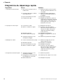
Diagramme de dépannage rapide
Symptôme Cause Solution
1. La pompe ne fonctionne pas. 1.1 Disjoncteur thermique ouvert ou 1.1.1 Vérifiez le fusible. Laissez le moteur
fusible sauté. refroidir avant de le redémarrer s’il a
surchauffé.
1.2 Connexion électrique ou alimen- 1.2.1 Vérifiez la batterie /l’alimentation
tation défectueuse. électrique, l’interrupteur général et
le câblage
1.4 Dysfonctionnement du moteur. 1.4.1 Remplacez la pompe.
1.5 Pompe/moteur gelé. 1.5.1 Dégelez la pompe et le système et
recherchez puis réparez les éventuels
dégâts du gel. Le démarrage d’une
pompe gelée peut endommager la
pompe et/ou le moteur
2. La pompe ne s’amorce pas. 2.1 Le réservoir est vide. 2.1.1 Remplissez le réservoir.
2.2 Débris sous/dans les clapets. 2.2.1 Ouvrez le corps de pompe en
dévissant les deux vis de fixation et
nettoyez les clapets. Nettoyez les
clapets de refoulement. (Viking
Power Vacuum.)
2.3 Membrane perforée. 2.3.1 Remplacez la membrane.
2.4 Fuite à l’entrée de la pompe. 2.4.1 Vérifiez le serrage des raccords de
tuyau.
2.5 Tuyauterie d’aspiration ou de 2.5.1 Vérifiez la tuyauterie et les clapets.
refoulement étranglée.
3. Débit/pression faible. 3.1 Fuite au refoulement de la pompe 3.1.1 Vérifiez le serrage des raccords.
Vérifiez l’état des tuyaux.
3.2 Membrane perforée. 3.2.1 Remplacez la membrane.
3.3 Dysfonctionnement du moteur. 3.3.1 Remplacez la pompe.
3.4 Débris sous/dans les clapets. 3.4.1 Ouvrez le corps de pompe en
dévissant les deux vis de fixation et
nettoyez les clapets. Nettoyez les
clapets de refoulement. (Viking
Power Vacuum.)
4. Pompe excessivement bruyante. 4.1 Tuyauterie d’aspiration ou de 4.1.1 Vérifiez la tuyauterie.
refoulement étranglée.
4.2 Etranglement au refoulement de 4.2.1 Vérifiez que les clapets sont ouverts.
la pompe/pression trop forte.
4.3 Moteur défectueux. 4.3.1 Remplacez la pompe.
18 Traduction du manuel d'instruction d'origine
> Français

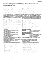
Aplicaciones usuales
La Viking Power 32/Vacuum es la bomba
de diafragma ideal para la descarga del
inodoro, aguas residuales y sentinas. Su
diseño compacto permite un montaje e
instalación que se adapta en gran medida
a las condiciones de la embarcación. La
bomba Viking Power Vacuum posee una gran
capacidad autocebante y es muy apropiada
para su instalación en un sistema de vacío.
Número de Modelo
Viking Power 32 12V 10-13373-03
Viking Power 32 24V 10-13373-04
Viking Power Vacuum 12V 10-13373-07
(doble válvula antirretorno)
Viking Power Vacuum 24V 10-13373-08
(doble válvula antirretorno)
Características
• 32 L/min a caudal abierto – Viking
Power 32
• 30 L/min a una presión de 0,1 bar –
Viking Power 32
• 24 L/min a caudal abierto – Viking
Power Vacuum
• 22 L/min a una presión de 0,1 bar –
Viking Power Vacuum
• Diseño compacto
• Conexión: manguera de 1½” (Ø 38 mm)
• Funcionamiento silencioso
• Autocebante hasta 2,5 m – Viking Power 32
• Autocebante hasta 5 m – Viking
Power Vacuum
• La cabeza de bomba puede girar 360°
• Funcionamiento en seco sin que se
produzcan daños
• No es necesario el uso de filtro
• Transmisión basada en cojinetes de bolas
• Bajo consumo (40W a una presión de
0,1 bar)
• Accionamiento a manivela
• Cumple con la Norma de calidad
ISO15083 (Pequeñas Embarcaciones.
Sistemas de Bombeo de Sentinas, para
embarcaciones desde 12 m / 40 pies)
Principio de funcionamiento
Bomba de diafragma autocebante con una
sola cámara. A fin de lograr una adecuada
capacidad autocebante y una solución sin
uso de filtro, la bomba está diseñada con una
sola membrana de grandes dimensiones y una
larga carrera. De esta manera, en cada carrera
se impulsa una gran cantidad de agua a
través del cuerpo de la bomba, lo cual permite
expulsar todo tipo de desechos (comparar con
un desatascador de caucho para fregaderos).
Descripción técnica
Cuerpo: Nylon
Válvulas: Nitrilo
Diafragma: Nitrilo Reforzado
Tornillos: Acero inoxidable
Pedestal: Acero galvanizado pintado
Conexión: Manguera de 1½”
Altura de descarga
máxima: 4 m
Altura de aspiración
máxima: 2,5 y 5 m respectivamente
(Viking Power Vacuum)
Altura de descarga +
aspiración máxima: 5 m
Motor: 40W a una presión de 0,1 bar,
12/24V (con protección
térmica incorporada)
Tipo de fusibles: 12A – 12V / 6 A – 24V
La bomba dispone del certificado de
conformidad CE de acuerdo con las
siguientes normas:
• EN55014-1:2000/Perturbación Radio-
eléctrica
• ISO8846: Pequeñas Embarcaciones
– Dispositivos Eléctricos – Protección
contra la inflamación de los ambientes
gaseosos inflamables
• ISO8849:2003/ Pequeñas Embarcaciones
– Bombas de sentina con motor eléctrico
• ISO10133:2001 Pequeñas Embarcaciones
– Sistemas Eléctricos – Instalaciones de
Corriente Continua a Muy Baja Tensión
Bomba Viking Power 32/Viking Power Vacuum con
motor de 12/24V
Por favor lea las siguientes instrucciones antes de proceder a la instalación.
19
Traducción de instrucciones originales
> Español

Plano
Ver página 27
Datos de Presión y Capacidad –
Viking Power 32
Presión Flujo Amperios
Bar kPa Psi l/min USGPM 12V 24V
0 0 0 34.4 9.1 2.5 1.2
0.1 10 1.5 30.8 8.1 3.3 1.6
0.2 20 2.9 27.1 7.2 4.2 2.1
0.3 30 4.4 23.5 6.2 5.0 2.5
0.4 40 5.8 20.0 5.3 5.6 2.8
0.5 50 7.2 16.7 4.4 6.1 3.1
Fusible requerido 12 A 6 A
Instalación y mantenimiento
Instalación
• Coloque la bomba en un lugar seco.
• Si la bomba se instala en posición vertical,
el motor debe estar ubicado encima del
cuerpo de la bomba.
• Marque las posiciones de los tornillos y
haga los agujeros guía.
• Monte la bomba utilizando tornillos de
acero inoxidable y las arandelas provistas.
Asegúrese de que los espaciadotes de
plástico estén en la posición correcta.
NOTA: Tenga cuidado de no ajustar
demasiado las patas de caucho que sirven
para amortiguar las vibraciones.
• Instale las válvulas antirretorno de salida
y atornille las conexiones - Viking Power
Vacuum.
NOTA: Las válvulas antirretorno se instalan
con su extremo puntiagudo apuntando en
dirección de la corriente. Ver plano.
• Se recomienda el uso de tubería flexible
reforzada.
• Utilice abrazaderas de acero inoxidable
para fijar la tubería a las conexiones y otros
acoplamientos presentes en el sistema.
Instalación Eléctrica
La bomba debe instalarse de conformidad
con la norma ISO 10133 (Pequeñas
Embarcaciones – Sistemas Eléctricos –
Instalaciones de Corriente Continua a Muy
Baja Tensión).
NOTA: El fusible debe estar protegido
contra la inflamación.
El motor está equipado con una protección
térmica incorporada a fin de evitar el
sobrecalentamiento. La protección se
restablece automáticamente cuando
el motor se enfría. Para una correcta
instalación remitirse al diagrama de
conexiones. El cable negativo debe ser
negro.
Seleccione las dimensiones del cable de
conformidad con su longitud total (ver
Cuadro). Las conexiones eléctricas deben
estar selladas con un material sellador de
uso marino.
NOTA: Antes de proceder a la instalación
de los sistemas de control eléctrico,
verifique que el equipo que se utilizará
posee la capacidad nominal suficiente para
soportar la intensidad de la corriente del
motor. Una baja tensión podría causar un
sobrecalentamiento del motor.
Mantenimiento
Las válvulas ubicadas dentro del cuerpo
de la bomba deben limpiarse regularmente
a fin de eliminar desechos y evitar así
una disminución del rendimiento y una
insuficiente capacidad autocebante. Esto
se realiza desatornillando la abrazadera
que sujeta el cuerpo de la bomba y luego
abriéndolo. Las válvulas anirretorno de
salida están ubicadas encima de las
conexiones. (Viking Power Vacuum.) NOTA:
Verifique que la bomba esté desconectada
de la alimentación eléctrica.
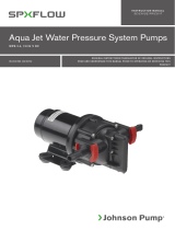
Diagrama de conexiones
Los otros dispositivos eléctricos tal como
el interruptor y los relés deben instalarse
entre la bomba y el polo positivos (+) de
la batería (en el cable rojo).
Bomba
Fusible
principal
Max 0.2 m
Rojo
Negro
+
–
20 Traducción de instrucciones originales
> Español
Sidan laddas ...
Sidan laddas ...
Sidan laddas ...
Sidan laddas ...
Sidan laddas ...
Sidan laddas ...
Sidan laddas ...
Sidan laddas ...
Sidan laddas ...
Sidan laddas ...
Sidan laddas ...
Sidan laddas ...
-
 1
1
-
 2
2
-
 3
3
-
 4
4
-
 5
5
-
 6
6
-
 7
7
-
 8
8
-
 9
9
-
 10
10
-
 11
11
-
 12
12
-
 13
13
-
 14
14
-
 15
15
-
 16
16
-
 17
17
-
 18
18
-
 19
19
-
 20
20
-
 21
21
-
 22
22
-
 23
23
-
 24
24
-
 25
25
-
 26
26
-
 27
27
-
 28
28
-
 29
29
-
 30
30
-
 31
31
-
 32
32


SPX FLOW Viking Power Waste Water Pump Användarmanual
- Typ
- Användarmanual
på andra språk
Relaterade papper
-
 SPX FLOW Viking Power Waste Water Pump Användarmanual
-
 SPX FLOW Viking Compact Användarmanual
-
 SPX FLOW Viking Universal Användarmanual
-
 SPX FLOW Ultima Bilge 1250GPH Användarmanual
-
 SPX FLOW Viking Hand Pump Användarmanual
-
 SPX FLOW Aqua jet WPS Användarmanual
-
 SPX FLOW Aqua Jet WD Pump Användarmanual
-
 SPX FLOW Aqua Jet Användarmanual
-
 SPX FLOW Aqua Jet Användarmanual
-
 SPX FLOW Bilge, Deck Wash and Refueling pump Användarmanual


