SPX FLOW Viking Hand Pump Användarmanual
- Typ
- Användarmanual

INSTRUCTION MANUAL
ORIGINAL INSTRUCTIONS/TRANSLATION OF ORIGINAL INSTRUCTIONS
READ AND UNDERSTAND THIS MANUAL PRIOR TO OPERATING OR SERVICING THIS
PRODUCT
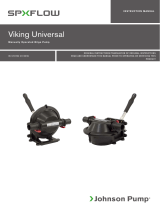
Hand Driven Bilge Pump
VIKING BULKHEAD & VIKING THRUDECK
IB-112 R06 (06/2019)

INDEX INDICE
Svenska .......................................................................................................................... 3
English ............................................................................................................................5
Deutsch .......................................................................................................................... 7
Français ..........................................................................................................................9
España ..........................................................................................................................11
Italiano ..........................................................................................................................13
Made by SPX FLOW Johnson Pump®
SE: Besök www.spxflow.com för mer information om vår världsomspännande organisation, våra godkännanden,
certifieringar och lokala representanter. SPX FLOW, Inc. förbehåller sig rätten att ändra design och material utan
föregående avisering. Designelement, konstruktionsmaterial och dimensioner som beskrivs i denna bulletin gäller
endast som information och skall alltid bekräftas skriftligt för att vara gällande.
EN: For more information about our worldwide locations, approvals, certifications, and local representatives, please visit
www.spxflow.com. SPX FLOW, Inc. reserves the right to incorporate our latest design and material changes without
notice or obligation. Design features, materials of construction and dimensional data, as described in this bulletin,
are provided for your information only and should not be relied upon unless confirmed in writing.
DE: Für weitere Informationen über unsere weltweiten Standorte, Zulassungen, Zertifizierungen und unsere Vertreter
vor Ort, besuchen Sie bitte unsere Webseite: www.spxflow.com. Die SPX FLOW, Inc. behält sich das Recht vor,
die neuesten Konstruktions- und Werkstoffänderungen ohne vorherige Ankündigung und ohne Verpflichtung hierzu
einfließen zu lassen. Konstruktive Ausgestaltungen, Werkstoffe sowie Maßangaben, wie sie in dieser Mitteilung
beschrieben sind, sind nur zur Information. Alle Angaben sind unverbindlich, es sei denn, sie wurden schriftlich
bestätigt.
FR: Pour plus d’information sur nos succursales internationales, nos approbations, nos certifications et nos
représentants locaux, veuillez consulter notre site Internet au www.spxflow.com. SPX FLOW, Inc. se réserve le droit
d’incorporer nos plus récents concepts ainsi que tout autre modification importante sans préavis ou obligation. Les
éléments décoratifs, matériaux de construction et les données dimensionnelles, tels qu’énoncés dans ce communiqué,
sont fournis pour votre information seulement et ne doivent pas être considérés comme officiels à moins d’avis
contraire par écrit.
ES: Para más información sobre nuestras oficinas a nivel mundial, aprobaciones, certificaciones y representantes
locales, por favor visite www.spxflow.com. SPX FLOW, Inc. se reserva el derecho de incorporar nuestro diseño más
reciente y cambios materiales sin necesidad de notificación previa u obligación de ningún tipo. Características de
diseño, materiales de construcción y dimensiones, tal y como están descritas en este boletín, son proporcionadas sólo
con fines informativos y no deben ser usados como referencia a menos que sean confirmados por escrito.
IT: Per ottenere maggiori informazioni sulle nostre sedi nel mondo, autorizzazioni, certificazioni, e rappresentanti locali,
potete visitare il sito www.spxflow.com. La SPX FLOW, Inc. si riserva il diritto di apportare cambiamenti ai propri design
e materiali senza preavviso o vincolo. Le caratteristiche del design, i materiali di costruzione e i dati dimensionali, così
come descritti nel presente bollettino, sono forniti solo per vostra informazione e non saranno oggetto di obbligazione
salvo autorizzazione confermata per iscritto.

3
Översättning av originalinstruktionerna
> Svenska
Kapacitet
Vid 1 m sughöjd: 0,9 liter/slag
Kapacitet vid:
60 slag/min 54 l/min
80 slag/min 72 l/min
100 slag/min 90 l/min
Max sughöjd: 4 m
Installation
Viking Thrudeck
När Thrudeck monteras på vertikal vägg
ska märkningen ”UP” på monterings-
ringen vara uppåt.
För montering se håltagningsschema,
nästa sida. Dimensionerna är i tum och
mm. Yttre kanten av det stora hålet
ska rundas med 2 mm radie. Fyra M6
x 40 fästskruvar med cylindriskt huvud
medlevereras.
Innan Thrudeck monteras ska tätnings-
bälgen installeras. För att underlätta
påträdandet av bälgen på hävarmen,
talka i hålet på bälgen. Håll pumpen
bakom väggen och dra igenom bälgen,
sätt täckbrickan på plats och montera
skruvarna.
Viking Bulkhead
För montering av Bulkhead, använd
5 mm eller 6 mm skruv med cylindriskt
huvud och krysspår.
Typiska användningsområden
Länspump och toalettpump.
Teknisk beskrivning
Pumphus: PP
Axel: Syrafast stål SS2343
Skruvar: Syrafast stål SS2343
Gummidetaljer: Nitril
Pumpspak: Eloxerad aluminium
Anslutning: 1
1/2” (38 mm) alt
1” slang (25 mm)
Diameter: 164 mm
Höjd: 133 mm
Max bredd: 253 mm
Spaklängd: 285 mm
Vikt: 2 kg
Modellspecifikation
Typ Art nr
Viking Thrudeck 1 1/2” 70-50005
Viking Thrudeck 1” 70-50025
Viking Bulkhead 1 1/2” 70-50007
Viking Bulkhead 1” 70-50027
Viking Thrudeck
För montering bakom en vertikal vägg
eller under däck/durk med tätningsbälg,
komplett med täckbricka.
Viking Bulkhead
För montering ovanpå durk. Horisontell
spak.
Båda modellerna
Monteringsringen är försedd med inbygg-
da muttrar för montering bakom vägg
eller under däck/durk och hål för fastsätt-
ning ovanpå en yta.
Flödesriktningen genom pumpen är
markerad med en pil. Riktningen kan
lätt ändras i åtta olika lägen genom att
demontera åtta skruvar som håller ihop
pumphus och monteringsring.
Manuell länspump

4Översättning av originalinstruktionerna
> Svenska
Pos Nos Benämning Art No
1 1 Monteringsring (Thrudeck) 74-50054
1 Monteringsring (Bulkhead) 74-50079
2 4 Låsbricka 0.0357.001
3 1 Axel, 71 mm 74-50069
4 1 Axel, 86 mm 74-50068
5 16 Skruv 0.0140.201
6 2 Ventil 74-50062
7 2 O-ring 0.2172.557
8 1 Inlopp 1 1/2” 74-50052
1 Inlopp 1” 74-50086
9 4 Skruv 0.0140.202
10 1 Lock 74-50055
11 1 O-ring 0.2172.647
12 1 Pumphus 74-50051
13 1 Utlopp 1 1/2” 74-50053
1 Utlopp 1” 74-50087
14 1 Kolvplatta 74-50057
15 1 Membran 74-50063
16 1 Kolv 74-50056
17 1 Spak 74-50067
18 1 Hävarm (Bulkhead) 74-50077
19 1 Hävarm (Thrudeck) 74-50066
20 1 Bälg (Thrudeck) 74-50075
21 1 Täckplatta (Thrudeck) 74-50078
22 4 Skruv (Thrudeck) 0.0279.302
Avfallshantering/materialåtervinning
Vid avfallshantering ska produkten lämnas för destruktion/återvinning enligt gäl-
lande lagstiftning. Vid tillämpliga fall demonteras och sorteras produkten i ingående
materialfraktioner.
Reservdelslista (se sid 15)

5
Original instructions
> English
can be easily changed by removing the
eight screws which hold the pump body
and mounting ring together.
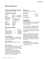
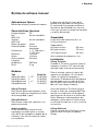
Capacity
At 1 m suction height: 0,9 l/stroke
Capacity at:
60 stroke/min 54 l/min
80 stroke/min 72 l/min
100 stroke/min 90 l/min
Max suction height: 4 m
Installation
Viking Thrudeck
When wall-mounting Thrudeck, note the
marking ”UP” on the mounting ring. Be
sure that the pump is mounted with this
marking up.
For mounting see the hole layout, next
page. The dimensions are in inches and
mm. The outside edge of the large hole
should be rounded approx. 2 mm.
Four metric 6 mm fastening screws are
supplied.
Before installing Thrudeck put some
talcum powder in the hole of the sealing
boot and slip it over the neck
of the lever. Then hold the pump in posi-
tion behind the wall or under the deck
and pull the boot through the hole. Hold
the coverplate in place and install the
screws.
Viking Bulkhead
For mounting Bulkhead, use # 12
screws with pan head (”pozidrive”).
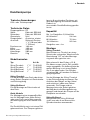
Typical applications
Bilge pump and macerator pump.
Design features
Pump body: PP
Shaft: Stainless steel
AISI 316
Screws: Stainless steel
AISI 316
Elastomers: Nitrile
Handle: Anodised aluminium
Connection: 1
1/2” (38 mm) or
1” hose (25 mm)
Diameter: 164 mm
Height: 133 mm
Max width: 253 mm
Handle length: 285 mm
Weight: 2 kg
Model specification
Type Part No
Viking Thrudeck 1 1/2” 70-50005
Viking Thrudeck 1” 70-50025
Viking Bulkhead 1 1/2” 70-50007
Viking Bulkhead 1” 70-50027
Viking Thrudeck
For installation behind vertical wall or
under deck with sealing boot, complete
with a coverplate.
Viking Bulkhead
For surface installation with horizontal
lever.
Both types
The mounting ring is provided with thread-
ed inserts for behind-wall or under-deck
installation and holes for surface installa-
tion.
The direction of flow through the pumps
is marked by an arrow on the housing and
Manually operated bilge pump

6Original instructions
> English
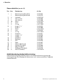
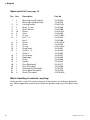
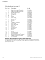
Spare parts list (see page 15)
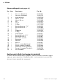
Pos Nos Description Part No
1 1 Mounting ring (Thrudeck) 74-50054
1 Mounting ring (Bulkhead) 74-50079
2 4 Locking washer 0.0357.001
3 1 Shaft, 71 mm 74-50069
4 1 Shaft, 86 mm 74-50068
5 16 Screw 0.0140.201
6 2 Valve 74-50062
7 2 O-ring 0.2172.557
8 1 Inlet 1 1/2” 74-50052
1 Inlet 1” 74-50086
9 4 Screw 0.0140.202
10 1 Cover 74-50055
11 1 O-ring 0.2172.647
12 1 Pump body 74-50051
13 1 Outlet 1 1/2” 74-50053
1 Outlet 1” 74-50087
14 1 Piston plate 74-50057
15 1 Diaphragm 74-50063
16 1 Piston 74-50056
17 1 Handle 74-50067
18 1 Pivot (Bulkhead) 74-50077
19 1 Pivot (Thrudeck) 74-50066
20 1 Sealing boot (Thrudeck) 74-50075
21 1 Cover plate (Thrudeck) 74-50078
22 4 Screw (Thrudeck) 0.0279.302
Waste handling & material recycling
At the products end of life, please dispose of the product according to applicable
law. Where applicable, please disassemble the product and recycle the parts mate-
rial.

7
Übersetzung der Original-Betriebanleitungen
> Deutsch
kann in 8 verschiedene Positionen mit
dem Montagering verschraubt werden.
Dadurch ist
eine variable Durchflußrichtung gewähr-
leistet.
Kapazität
Bei 1 m Saughöhe: 0,9 Liter/Hub
60 Hübe/min 54 l/min
80 Hübe/min 72 l/min
100 Hübe/min 90 l/min
Saughöhe, max.: 4 m
Montage
Viking Thrudeck
Beim Einbau von Thrudeck an einem
Schott oder senkrechter Wand muß die
Bezeichnung ”UP” auf dem Montage-
ring nach oben gerichtet sein.
Bohrschema für den Einbau, s.S. 8.
Die Abmessungen sind in Zoll und Milli-
meter angegeben. Die äußere Kante der
großen Bohrung ist mit einem Radius
von 2 mm abzurunden. Vier Zylinder-
schrauben M6 x 40 werden zur Befesti-
gung mitgeliefert.
Vor der Montage der Viking Thrudeck
ist der Dichtungsbalg einzubauen. Das
Aufziehen des Balges auf den Hebel
wird erleichtert, indem man Talkum
verwendet. Die Pumpe wird zur
Montage hinter das Schott gehalten,
der Balg durch die Montagebohrung
gezogen und danach die Pumpe mit der
Deckplatte verschraubt.
Viking Bulkhead
Beim Einbau der Viking Bulkhead
sind 5 mm oder 6 mm Kreuzschlitz-
Zylinderschrauben anzuwenden.
Typische Anwendungen
Lenz- oder Toilettenpumpe.
Technische Daten
Pumpengehäuse: PP
Welle: Edelstahl SS2343
Schrauben: Edelstahl SS2343
Gummiteile: Nitril
Pumpenhebel: Aluminium, eloxiert
Anschluß: Schlauch Durchm.
1
1/2” (38 mm) oder
1” (25 mm)
Durchmesser: 164 mm
Höhe: 133 mm
Breite, max.: 253 mm
Hebellänge: 285 mm
Gewicht: 2 kg
Modellvarianten
Typ Art.-Nr.
Viking Thrudeck 1 1/2” 70-50005
Viking Thrudeck 1” 70-50025
Viking Bulkhead 1 1/2” 70-50007
Viking Bulkhead 1” 70-50027
Viking Thrudeck
Für die Montage unter Deck oder hinter
einem Schott, komplett mit Deckscheibe
und Dichtungsbalg.
Viking Bulkhead
Für die Montage am Schott oder auf
dem Deck.
Beide Modelle
Der Montagering hat eingepreßte Mut-
tern für Montage hinter einem Schott
oder unter Deck sowie Bohrungen für
die Befestigung auf einer ebenen Fläc
he.
Die Durchflußrichtung ist mit einem Pfeil
gekennzeichnet. Das Pumpen-gehäuse
Handlenzpumpe

8Übersetzung der Original-Betriebanleitungen
> Deutsch
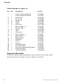
Ersatzteilliste (siehe Seite 15)
Pos Stk. Bezeichnung Artikel Nr.
1 1 Montagering (Thrudeck) 74-50054
1 Montagering (Bulkhead) 74-50079
2 4 Sicherungsscheibe 0.0357.001
3 1 Welle, 71 mm 74-50069
4 1 Welle, 86 mm 74-50068
5 16 Schraube 0.0140.201
6 2 Ventil 74-50062
7 2 O-Ring 0.2172.557
8 1 Pumpeneinlass 1 1/2” 74-50052
1 Pumpeneinlass 1” 74-50086
9 4 Schraube 0.0140.202
10 1 Schraubdeckel 74-50055
11 1 O-ring 0.2172.647
12 1 Pumpengehäuse 74-50051
13 1 Pumpenauslass 1 1/2” 74-50053
1 Pumpenauslass 1” 74-50087
14 1 Kolbenplatte 74-50057
15 1 Membrane 74-50063
16 1 Kolben 74-50056
17 1 Pumphebel 74-50067
18 1 Zentrumhebel (Bulkhead) 74-50077
19 1 Hebelarm (Thrudeck) 74-50066
20 1 Dichtungsbalg (Thrudeck) 74-50075
21 1 Befestigungsplatte (Thrudeck) 74-50078
22 4 Schraube (Thrudeck) 0.0279.302
Entsorgung/Recycling
Nach Lebensdauerende entsorgen Sie die Pumpe nach den örtlichen Vorschriften.
Nach Möglichkeit demontieren Sie Teile der Pumpe um sie dem Recycling-Process
zuzuführen.

9
Traduction du manuel d'instruction d'origine
> Français
Le sens de passage dans la pompe est
marqué par une flèche. Le sens peut
être facilement modifié suivant huit
positions différentes en enlevant les huit
vis de fixation du corps de pompe à la
bague de montage.
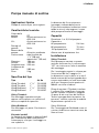
Débit
A une hauteur d’aspiration de 1 m:
0,9 litres/course
Débit à:
60 courses/min 54 l/min
80 courses/min 72 l/min
100 courses/min 90 l/min
Hauteur d’aspiration: 4 m
Installation
Viking Thrudeck
Pour le montage de Thrudeck sur une
cloison verticale, le repère «UP» sur la
bague de montage devra être en haut.
Pour le montage, voir le schéma de
perçage page 10. Les dimensions sont
en pouces et en mm. Le bord extérieur
du gros trou devra être arrondi avec un
rayon de 2 mm. Quatre vis de fixa-
tion M6x40 avec tête cylindrique sont
fournies.
Avant de monter Thrudeck, commencer
par installer le soufflet d’étanchéité.
Pour faciliter le montage du soufflet sur
le levier, mettre du talc dans le trou sur
le soufflet. Maintenir la pompe derrière
la cloison et faire passer le soufflet,
positionner la plaque de recouvrement
et mettre les vis.
Viking Bulkhead
Pour le montage de Bulkhead, utiliser
des vis cruciforme de 5 mm ou de 6 mm
avec tête cylindrique.
Types d’applications
Pompe de cale et pompe pour toilette.
Caractéristiques techniques
Corps de pompe: PP
Axe: Acier résistant
aux acides AISI 316
Visserie: Acier résistant
aux acides AISI 316
Pièces en
caoutchouc: Nitrile
Levier de pompe: Aluminium anodisé
Raccord: 1 1/2” (38 mm) ou
flexible 1” (25 mm)
Diamètre: 164 mm
Hauteur: 133 mm
Largeur maxi.: 253 mm
Longueur
de levier: 285 mm
Poids: 2 kg
Spécifications du modèle
Modèle Réference
Viking Thrudeck 1 1/2” 70-50005
Viking Thrudeck 1” 70-50025
Viking Bulkhead 1 1/2” 70-50007
Viking Bulkhead 1” 70-50027
Viking Thrudeck
Pour le montage derrière une paroi
verticale ou sous le pont avec un soufflet
d’étanchéité, complète avec plaque de
recouvrement.
Viking Bulkhead
Pour le montage au-dessus du pont.
Levier horizontal.
Les deux modèles
La bague de montage comporte des
écrous intégrés permettant le montage
derrière une cloison ou sous le pont et
des trous pour la fixation en surface.
Pompe de vidange manuelle

10 Traduction du manuel d'instruction d'origine
> Français
Liste de pièces (voir page 15)
Pos Nos Description Art No
1 1 Bague d’montage (Thrudeck) 74-50054
1 Bague d’montage (Bulkhead) 74-50079
2 4 Rondelle de blocage 0.0357.001
3 1 Axe, 71 mm 74-50069
4 1 Axe, 86 mm 74-50068
5 16 Vis 0.0140.201
6 2 Clapet 74-50062
7 2 Joint torique 0.2172.557
8 1 Entrée 1 1/2” 74-50052
1 Entrée 1” 74-50086
9 4 Vis 0.0140.202
10 1 Trappe de nettoyage 74-50055
11 1 Joint torique 0.2172.647
12 1 Corps de pompe 74-50051
13 1 Sortie 1 1/2” 74-50053
1 Sortie 1” 74-50087
14 1 Contre piston 74-50057
15 1 Membrane 74-50063
16 1 Piston 74-50056
17 1 Levier 74-50067
18 1 Pivot (Bulkhead) 74-50077
19 1 Pivot (Thrudeck) 74-50066
20 1 Soufflet d’étanchéité (Thrudeck) 74-50075
21 1 Plaque de fixation (Thrudeck) 74-50078
22 4 Vis (Thrudeck) 0.0279.302
Gestion des déchets/recyclage des matériaux
Lorsque le matériel arrivera en fin de vie, veuillez le mettre au rebut en fonction des
lois applicables. Lorsque c’est possible, veuillez démonter le matériel et recycler les
pièces pouvant l’être.

11
Traducción de instrucciones originales
> Español
La dirección del flujo a través de la
bomba está marcada con una flecha.
El sentido del flujo puede modificarse
fácilmente, desmontando los ocho tor-
nillos que sujetan el cuerpo de la bomba
y el anillo de montaje.
Capacidad
A una altura de aspiración de 1 m:
0,9 litros/impulso.
Capacidad a:
60 impulsos/min. 54 l/min.
80 impulsos/min. 72 l/min.
100 impulsos/min. 90 l/min.
Altura máxima de aspiración: 4 m
Instalación
Viking Thrudeck
Cuando la Thrudeck se monta sobre el
mamparo, la marca ”UP” del anillo de
montaje ha de orientarse hacia arriba.
Para el montaje, véase el croquis de
agujeros en la página 12. Las dimen-
siones se indican en pulgadas y
milímetros. El borde exterior del agujero
grande debe tener un radio de 2 mm.
Se incluyen cuatro tornillos de fijación
M6 x 40 con cabeza cilíndrica.
Antes de montar la Thrudeck hay que
instalar el fuelle de estanqueidad. Para
facilitar su introducción en la palanca,
aplicar polvos de talco en el orificio del
fuelle. Mantener la bomba detrás del
mamparo y hacer pasar el fuelle, poner
el anillo de montaje en su sitio y colocar
los tornillos.
Viking Bulkhead
Para el montaje de la Bulkhead, utilizar
tornillos de 5 ó 6 mm con cabeza
Philips.
Aplicaciones típicas
Bomba de achique y bomba trituradora.
Características técnicas
Cuerpo bomba: PP
Eje: Acero inoxidable
AISI 316
Tornillos: Acero inoxidable
AISI 316
Piezas de goma: Nitrilo
Palanca bomba: Aluminio
anodizado
Conexiones: 1
1/2” (38 mm) ó
1” (25 mm)
Diámetro: 164 mm
Altura: 133 mm
Ancho máximo: 253 mm
Longitud
de palanca: 285 mm
Peso: 2 kg
Modelos
Tipo Pieza No
Viking Thrudeck 1 1/2” 70-50005
Viking Thrudeck 1” 70-50025
Viking Bulkhead 1 1/2” 70-50007
Viking Bulkhead 1” 70-50027
Viking Thrudeck
Para montar detrás del mamparo o de-
bajo de la cubierta. Completa con fuelle
de estanqueidad y tapa.
Viking Bulkhead
Para montar sobre una superficie, con
palanca horizontal.
Ambos modelos
El aro de montaje está provisto de
espárragos roscados para su instala-
ción detrás del mamparo o debajo de la
cubierta y con orificios para fijar sobre
una superficie.
Bomba de achique manual

12 Traducción de instrucciones originales
> Español
Lista de piezas (ver página 15)
Pos Nos Descripción Part No
1 1 Cuerpo superior (Thrudeck) 74-50054
1 Cuerpo superior (Bulkhead) 74-50079
2 4 Anillo fijación 0.0357.001
3 1 Eje, 71 mm 74-50069
4 1 Eje, 86 mm 74-50068
5 16 Tornillo 0.0140.201
6 2 Válvula 74-50062
7 2 Junta tórica 0.2172.557
8 1 Racor entrada 1 1/2” 74-50052
1 Racor entrada 1” 74-50086
9 4 Tornillo 0.0140.202
10 1 Tapa 74-50055
11 1 Junta tórica 0.2172.647
12 1 Cuerpo inferior 74-50051
13 1 Racor salida 1 1/2” 74-50053
1 Racor salida 1” 74-50087
14 1 Platina pistón 74-50057
15 1 Membrana 74-50063
16 1 Pistón 74-50056
17 1 Palanca 74-50067
18 1 Pivote (Bulkhead) 74-50077
19 1 Pivote (Thrudeck) 74-50066
20 1 Fuelle de estanqueidad (Thrudeck) 74-50075
21 1 Platina (Thrudeck) 74-50078
22 4 Tornillo (Thrudeck) 0.0279.302
Desguace/Reciclado
Al final de la vida del equipo disponga de este de acuerdo a la ley. Donde sea de
aplicación desmonte el equipo y recicle los diferentes materiales.

13
Traduzione delle istruzioni originali
> Italiano
La direzione del flusso attraverso
la pompa è indicata dalla freccia.
E’ possibile cambiare la direzione smon-
tando le otto viti che tengono il corpo
della pompa all’anello di montaggio.
Capacità
Prevalenza 1 m: 0,9 litri/pompata
Capacità a:
60 pompate/min. 54 l/min.
80 pompate/min. 72 l/min.
100 pompate/min. 90 l/min.
Altezza max. di aspirazione 4 m.
Installazione
Viking Thrudeck
Se la pompa va montata su parete
verticale verificare che il contrassegno
”UP” sia rivolto verso l’alto al momento
del montaggio.
Per il montaggio seguire lo schema per
l’esecuzione dei fori, a pagina 14.
Le dimensioni sono in pollici e in mm. Il
bordo esterno del foro più grande deve
essere arrotondato con una lima tonda
da 2 mm. Vengono fornite quattro viti
M6x40 con testa cilindrica.
Prima di montare il Thrudeck installare
il soffietto. Per semplificare il montag-
gio del soffietto sul braccio, spargere
un poco di talco nel foro del soffietto.
Tenere la pompa dietro la parete e far
passare il soffietto, montare la rondella
di protezione e quindi le viti.
Viking Bulkhead
Per il montaggio del Bulkhead usare viti
a testa cilindrica con traccia a croce, da
5mm o 6 mm.
Applicazioni tipiche
Pompa di sentina e per servizi igienici.
Caratteristiche tecniche
Corpo della
pompa: PP
Albero: Acciaio anticorrosivo
AISI 316
Viti: Acciaio anticorrosivo
AISI 316
Dettagli di
gomma: Nitrile
Braccio della
pompa: Alluminio anodizzato
Connessione tubo flessibile da
1
1/2” (38 mm)
oppure da 1” (25 mm)
Diametro: 164 mm
Altezza: 133 mm
Larghezza max: 253 mm
Lunghezza del
braccio: 285 mm
Peso: 2 kg
Specifica del tipo
Tipo Art No
Viking Thrudeck 1 1/2” 70-50005
Viking Thrudeck 1” 70-50025
Viking Bulkhead 1 1/2” 70-50007
Viking Bulkhead 1” 70-50027
Viking Thrudeck
Per montaggio a paratia verticale
oppure sotto coperta, con soffietto di
tenuta, completa di coperchio.
Viking Bulkhead
Per montaggio sul ponte. Con braccio
orizzontale.
Entrambi modelli
La flangia di montaggio è dotata di dadi
per l’installazione dietro una parete o
sottocoperta, e fori per il montaggio su
una superficie.
Pompa manuale di sentina

14 Traduzione delle istruzioni originali
> Italiano
Pos Nos Descrizione Part No
1 1 Carcassa (Thrudeck) 74-50054
1 Carcassa (Bulkhead) 74-50079
2 4 Anello di fermo 0.0357.001
3 1 Albero, 71 mm 74-50069
4 1 Albero, 86 mm 74-50068
5 16 Vite 0.0140.201
6 2 Valvola 74-50062
7 2 O-Ring 0.2172.557
8 1 Boccola d’entrata 1 1/2” 74-50052
1 Boccola d’entrata 1” 74-5 008 6
9 4 Vite 0.0140.202
10 1 Coperchio 74-50055
11 1 O-Ring 0.2172.647
12 1 Corpo pompa 74-50051
13 1 Boccola d’uscita 1 1/2” 74-50053
1 Boccola d’uscita 1” 74-50087
14 1 Base dello stantuffo 74-50057
15 1 Membrana 74-50063
16 1 Stantuffo 74-50056
17 1 Braccio 74-50067
18 1 Giunto snodato (Bulkhead) 74-50077
19 1 Giunto snodato (Thrudeck) 74-50066
20 1 Soffietto di tenuta (Thrudeck) 74-50075
21 1 Piastra di fissaggio (Thrudeck) 74-50078
22 4 Vite (Thrudeck) 0.0279.302
Gestione dei rifiuti/riciclaggio dei materiali
Al termine della vita del prodotto si prega di smaltire il prodotto secondo le leggi in
vigore per queste operazioni. Quando possibile, si raccomanda di smontare il pro-
dotto e riciclare i materiali dei componenti.
Elenco delle parti (vedi pagina 15)

15
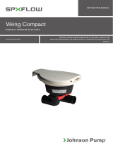
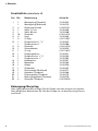
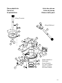
Reservdelslista
Parts list
Ersatzteilliste
Liste des pièces
Lista de piezas
Elenco delle parti
1
2
3
4
16
5
6
7
8
5910
11
5
7
6
13
14
12
15
17
22
21
20
19
18
17
Viking Thrudeck
Viking Bulkhead
Båda modellerna
Both types
Beide Modelle
Les deux modèles
Ambos modelos
Entrambi modelli

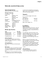
16
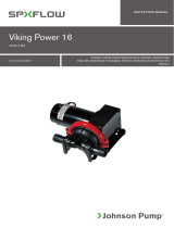
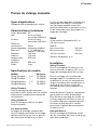
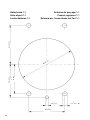
Hålschema 1:1
Hole alyout 1:1
Lochschablone 1:1
Schéma de perçage 1:1
Croquis agujeros 1:1
Schema per l’esecuzione dei fori 1:1
67 (2 5/8”)57 (21/4”)
51 (2”)
ø 5 (3/16”)
57 (21/4”)
ø 7 (9/32”) 4x?
89 (3
1
/2”)


Hand Driven Bilge
Pump
VIKING BULKHEAD & VIKING
THRUDECK
IB-112 R06 ISSUED 06/2019 COPYRIGHT © 2019 SPX FLOW INC.
Customer Service & Support - Johnson Pump Marine
SE +46 19 21 83 10
johnson-pump.marine@spxflow.com
US +1 847 671-7867
jp-customerservice@spxflow.com
AUS +61 03 9589 9222
ft.aus.cs@spxflow.com
For more information about our worldwide locations, approvals, certifications,
and local representatives, visit Johnson Pump - Marine at www.spxflow.com
SPX FLOW, Inc. reserves the right to incorporate our latest design and material changes without notice or obligation.
Design features, materials of construction and dimensional data, as described in this bulletin, are provided for your
information only and should not be relied upon unless confirmed in writing. Please contact your local sales representative
for product availability in your region. For more information visit www.spxflow.com.
The green “
”
and “
” are trademarks of SPX FLOW, Inc.
-
 1
1
-
 2
2
-
 3
3
-
 4
4
-
 5
5
-
 6
6
-
 7
7
-
 8
8
-
 9
9
-
 10
10
-
 11
11
-
 12
12
-
 13
13
-
 14
14
-
 15
15
-
 16
16
-
 17
17
-
 18
18
-
 19
19
-
 20
20