Yamaha DSP-1 Användarmanual
- Kategori
- Processorer
- Typ
- Användarmanual
Denna manual är också lämplig för

OWNER’S MANUAL
MODE D’EMPLOI
OWNER’S MANUAL
MODE D’EMPLOI
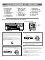
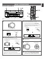
U C A
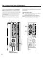
NATURAL SOUND AV AMPLIFIER DSP A1
CINEMA DSP
7ch
VOLUME
INPUT SELECTOR
TAPE 2 MON
/EXT. DECODER
l6
20
28
40
60
l2
8
4
2
0
–dB
PHONES BASS
EXTENSION
BASS TREBLE BALANCE
DVD/VCR 3
VIDEO AUX
REC OUT
VCR 1
VCR 2
TV/DBS
LD
SOURCE
CD
MD/TAPE 1
VIDEO AUX
NEXT
INPUT MODE
SET MENU PROGRAM EFFECT
STANDBY/ON
55
4
3
2
l
0
l
2
3
4
LR
55
4
3
2
l
0
l
2
3
4
55
4
3
2
l
0
l
2
3
4

1 Read Instructions – All the safety and operating
instructions should be read before the unit is operated.
2 Retain Instructions – The safety and operating instructions
should be retained for future reference.
3 Heed Warnings – All warnings on the unit and in the
operating instructions should be adhered to.
4 Follow Instructions – All operating and other instructions
should be followed.
5 Water and Moisture – The unit should not be used near
water – for example, near a bathtub, washbowl, kitchen
sink, laundry tub, in a wet basement, or near a swimming
pool, etc.
6 Carts and Stands – The unit should be used only with a
cart or stand that is recommended by the manufacturer.
6A A unit and cart combination should be
moved with care. Quick stops, excessive
force, and uneven surfaces may cause
the unit and
cart combination to overturn.
7 Wall or Ceiling Mounting – The unit
should be mounted to a wall or ceiling only as
recommended by the manufacturer.
8 Ventilation – The unit should be situated so that its
location or position does not interfere with its proper
ventilation. For example, the unit should not be situated
on a bed, sofa, rug, or similar surface, that may block the
ventilation openings; or placed in a built-in installation,
such as a bookcase or cabinet that may impede the flow
of air through the ventilation openings.
9 Heat – The unit should be situated away from heat
sources such as radiators, stoves, or other appliances
that produce heat.
10 Power Sources – The unit should be connected to a
power supply only of the type described in the operating
instructions or as marked on the unit.
11 Power-Cord Protection – Power-supply cords should be
routed so that they are not likely to be walked on or
pinched by items placed upon or against them, paying
particular attention to cords at plugs, convenience
receptacles, and the point where they exit from the unit.
12 Cleaning – The unit should be cleaned only as
recommended by the manufacturer.
13 Nonuse Periods – The power cord of the unit should be
unplugged from the outlet when left unused for a long
period of time.
14 Object and Liquid Entry – Care should be taken so that
objects do not fall into and liquids are not spilled into the
inside of the unit.
15 Damage Requiring Service – The unit should be serviced
by qualified service personnel when:
A. The power-supply cord or the plug has been
damaged; or
B. Objects have fallen, or liquid has been spilled into the
unit; or
C. The unit has been exposed to rain; or
D. The unit does not appear to operate normally or
exhibits a marked change in performance; or
E. The unit has been dropped, or the cabinet damaged.
16 Servicing – The user should not attempt to service the unit
beyond those means described in the operating
instructions. All other servicing should be referred to
qualified service personnel.
17 Power Lines – An outdoor antenna should be located
away from power lines.
18 Grounding or Polarization – Precautions should be taken
so that the grounding or polarization is not defeated.
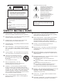
SAFETY INSTRUCTIONS
RISK OF ELECTRIC SHOCK
DO NOT OPEN
CAUTION: TO REDUCE THE RISK OF
ELECTRIC SHOCK, DO NOT REMOVE
COVER (OR BACK). NO USER-SERVICEABLE
PARTS INSIDE. REFER SERVICING TO
QUALIFIED SERVICE PERSONNEL.
The lightning flash with arrowhead
symbol, within an equilateral triangle,
is intended to alert you to the
presence of uninsulated “dangerous
voltage” within the product’s
enclosure that may be of sufficient
magnitude to constitute a risk of
electric shock to persons.
The exclamation point within an
equilateral triangle is intended to alert
you to the presence of important
operating and maintenance
(servicing) instructions in the
literature accompanying the
appliance.
•
Explanation of Graphical Symbols
CAUTION
WARNING
TO REDUCE THE RISK OF FIRE OR ELECTRIC
SHOCK, DO NOT EXPOSE THIS UNIT TO RAIN
OR MOISTURE.
IMPORTANT
Please record the serial number of this unit in
the space below.
Model:
Serial No.:
The serial number is located on the rear of
the unit.
Retain this Owner’s Manual in a safe place
for future reference.

1
English
SPECIAL NOTES FOR FCC COMPOSITE DEVICE (for US customers only)
This device is a composite system. The digital device component may not cause harmful interference.
1. IMPORTANT NOTICE : DO NOT MODIFY THIS UNIT!
This product, when installed as indicated in the
instructions contained in this manual, meets FCC
requirements. Modifications not expressly approved by
Yamaha may void your authority, granted by the FCC, to
use the product.
2. IMPORTANT : When connecting this product to
accessories and/or another product use only high quality
shielded cables. Cable/s supplied with this product
MUST be used. Follow all installation instructions.
Failure to follow instructions could void your FCC
authorization to use this product in the USA.
3. NOTE : This product has been tested and found to
comply with the requirements listed in FCC Regulations,
Part 15 for Class “B” digital devices. Compliance with
these requirements provides a reasonable level of
assurance that your use of this product in a residential
environment will not result in harmful interference with
other electronic devices.
This equipment generates/uses radio frequencies and, if
not installed and used according to the instructions
found in the users manual, may cause interference
harmful to the operation of other electronic devices.
Compliance with FCC regulations does not guarantee that
interference will not occur in all installations. If this product
is found to be the source of interference, which can be
determined by turning the unit “OFF” and “ON”, please try
to eliminate the problem by using one of the following
measures:
Relocate either this product or the device that is being
affected by the interference.
Utilize power outlets that are on different branch (circuit
breaker or fuse) circuits or install AC line filter/s.
In the case of radio or TV interference, relocate/reorient the
antenna. If the antenna lead-in is 300 ohm ribbon lead,
change the lead-in to coaxial type cable.
If these corrective measures do not produce satisfactory
results, please contact the local retailer authorized to
distribute this type of product. If you can not locate the
appropriate retailer, please contact Yamaha Electronics
Corp., U.S.A. 6660 Orangethorpe Ave, Buena Park, CA
90620.
The above statements apply ONLY to those products
distributed by Yamaha Corporation of America or its
subsidiaries.
FCC INFORMATION (for US customers only)
YAMAHA and the Electronic Industries Association’s
Consumer Electronics Group want you to get the most out of
your equipment by playing it at a safe level. One that lets the
sound come through loud and clear without annoying blaring
or distortion – and, most importantly, without affecting your
sensitive hearing.
Since hearing damage from loud sounds is often
undetectable until it is too late, YAMAHA and the
Electronic Industries Association’s Consumer
Electronics Group recommend you to avoid
prolonged exposure from excessive volume levels.
We Want You Listening For A Lifetime (for US customers only)
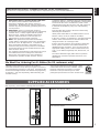
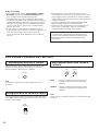
After unpacking, check that the following parts are included.
SUPPLIED ACCESSORIES
Remote Control Transmitter Batteries (size AA, R6, UM-3)
User function stickers

2
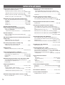
CONTENTS
Thank you for selecting this YAMAHA AV Amplifier.
SAFETY INSTRUCTIONS
...................................................... Inside of the Front Cover
SUPPLIED ACCESSORIES ............................................... 1
FEATURES ........................................................................... 3
CAUTION .............................................................................. 3
NOTES ABOUT THE REMOTE CONTROL
TRANSMITTER .................................................................... 4
PROFILE OF THIS UNIT ..................................................... 5
SPEAKER SETUP ............................................................... 8
CONNECTIONS ................................................................. 10
CONNECTING AUDIO/VIDEO SOURCE EQUIPMENT
TO THIS UNIT..................................................................... 10
CONNECTING SPEAKERS.............................................. 18
PLUGGING IN THIS UNIT................................................. 22
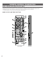
CONTROLS AND THEIR FUNCTIONS ......................... 23
FRONT PANEL................................................................... 23
DISPLAY PANEL ................................................................ 25
ADJUSTMENTS BEFORE USING THIS UNIT ............. 26
SELECTING THE OUTPUT MODES SUITABLE FOR
YOUR SPEAKER SYSTEM (IN THE “SET MENU” MODE)
............................................................................................... 26
SPEAKER BALANCE ADJUSTMENT............................. 29
ADJUSTMENTS IN THE “SET MENU” MODE ............ 32
BASIC OPERATIONS ....................................................... 39
TO PLAY A SOURCE......................................................... 39
TO RECORD A SOURCE TO TAPE (OR MD)
(OR DUBBING FROM A TAPE TO ANOTHER)............. 42
FOR SOUND CONTROL ON THIS UNIT........................ 44
USING DIGITAL SOUND FIELD PROCESSOR (DSP)
.............................................................................................. 45
PLAYING A SOURCE WITH AN EFFECT OF THE
DIGITAL SOUND FIELD PROCESSOR (DSP) .............. 45
ADJUSTING OUTPUT LEVEL OF THE CENTER, RIGHT
REAR, LEFT REAR, FRONT EFFECT SPEAKERS AND
SUBWOOFER .................................................................... 48
BRIEF OVERVIEW OF DIGITAL SOUND FIELD
PROGRAMS ....................................................................... 50
ON SCREEN DISPLAY .................................................... 55
CREATING YOUR OWN SOUND FIELDS .................... 56
SELECTING AND EDITING PROGRAM PARAMETERS
............................................................................................... 57
DESCRIPTIONS OF THE DIGITAL SOUND FIELD
PARAMETERS ................................................................... 58
SETTING THE SLEEP TIMER ......................................... 61
REMOTE CONTROL TRANSMITTER ........................... 62
BASIC OPERATIONS (When the lid is open) ................. 62
LEARNING NEW CONTROL FUNCTIONS
(When the lid is open).......................................................... 64
USING OPERATION CONTROL KEYS
(When the lid is closed) ...................................................... 66
MACRO OPERATIONS (When the lid is closed) ............ 68
LEARNING A NEW FUNCTION ....................................... 70
MAKING A NEW MACRO ................................................. 71
CLEARING LEARNED FUNCTIONS .............................. 72
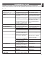
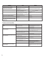
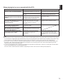
TROUBLESHOOTING ...................................................... 73
SPECIFICATIONS ............................................................. 76

3
English
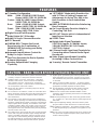
●
7 Speaker Configuration
Main: 110W + 110W (8Ω) RMS Output
Power, 0.015% THD, 20–20,000 Hz
Center: 110W (8Ω) RMS Output Power,
0.015% THD, 20–20,000 Hz
Rear: 110W + 110W (8Ω) RMS Output
Power, 0.015% THD, 20–20,000 Hz
Front: 35W + 35W (8Ω) RMS Output
Power, 0.05% THD, 1 kHz
●
Digital Sound Field Processor
●
Dolby Digital (AC-3) Decoder
●
Dolby Pro Logic Surround Decoder
●
DTS Decoder
●
CINEMA DSP: Theater-like Sound
Experience by the Combination of
YAMAHA DSP Technology and Dolby
Surround or DTS
●
Automatic Input Balance Control for
Dolby Pro Logic Surround
●
Test Tone Generator for Easier Speaker
Balance Adjustment
●
Speaker Output Mode Changing
Capability
●
“SET MENU” Mode which Provides You
with 12 Titles of Setting Changes and
Adjustments for Using This Unit in the
Best Condition in Your Audio/Video
System
● BASS EXTENSION Switch for Reinforcing
Bass Response
● On Screen Display Function Helpful in
Controlling This Unit
●
REC OUT Selector which is Independent of
Input Source Selection
● SLEEP Timer
●
Digital Audio Signal Terminals:
5 OPTICAL Inputs, 3 COAXIAL Inputs,
1 DOLBY DIGITAL (AC-3) RF Input,
1 OPTICAL Output
●
6 Channel Audio Signal Input Terminals for
Connecting with an External Audio Signal
Decoder etc.
● Video Signal Input/Output Capability
(Including S Video Connections)
●
“Learning” Remote Control Transmitter
FEATURES
1. To assure the finest performance, please read this manual
carefully. Keep it in a safe place for future reference.
2. Install this unit in a cool, dry, clean place – away from
windows, heat sources, sources of excessive vibration,
dust, moisture and cold. Avoid sources of humming
(transformers, motors). To prevent fire or electrical shock,
do not expose the unit to rain or water.
3. Never open the cabinet. If something drops into the set,
contact your dealer.
4. Do not use force on switches, controls or connection wires.
When moving the unit, first disconnect the power plug and
the wires connected to other equipment. Never pull the
wires themselves.
5. The openings on the cabinet assure proper ventilation of
the unit. If these openings are obstructed, the temperature
inside the cabinet will rise rapidly. Therefore, avoid placing
objects against these openings, and install the unit in well-
ventilated condition. Make sure to allow a space of at least
10 cm behind, 10 cm on the both sides and 30 cm above
the top panel of the unit. Otherwise it may not only damage
the unit, but also cause fire.
6. The voltage to be used must be the same as that specified
on this unit. Using this unit with a higher voltage than that
which is specified is dangerous and may result in a fire or
other type of accident causing damage. YAMAHA will not
be held responsible for any damage resulting from use of
this unit with a voltage other than that which is specified.
7. Digital signals generated by this unit may interfere with
other equipment such as tuners, receivers or TVs. Move
this unit farther away from such equipment if interference
is observed.
8. Always set the VOLUME control to “–
∞
” before starting
the audio source play. Increase the volume gradually to an
appropriate level after playback has been started.
9. Do not attempt to clean the unit with chemical solvents;
this might damage the finish. Use a clean, dry cloth.
10.Be sure to read the “TROUBLESHOOTING” section
regarding common operating errors before concluding that
the unit is faulty.
11.When not planning to use this unit for long periods of time
(ie., vacation, etc.), disconnect the AC power plug from the
wall outlet.
12.To prevent lightning damage, disconnect the AC power
plug and antenna cable when there is an electrical storm.
13.Grounding or polarization – Precautions should be taken
so that the grounding or polarization of an appliance is not
defeated.
14.Do not connect an audio equipment to the AC outlet on the
rear panel if the equipment requires more power than the
outlet is rated to provide.
CAUTION : READ THIS BEFORE OPERATING YOUR UNIT.

4
This unit is not disconnected from the AC power source as
long as it is connected to the wall outlet, even if this unit
itself is turned off. This state is called the standby mode.
In this state, this unit is designed to consume a very small
quantity of power.
Voltage Selector (China and General Models only)
The voltage selector on the rear panel of this unit must
be set for your local main voltage BEFORE plugging into
the AC main supply.
Voltages are 110/120/220/240 V AC, 50/60 Hz.
FREQUENCY STEP switch (China and General Models
only)
Because the interstation frequency spacing differs in
different areas, set the FREQUENCY STEP switch (located
at the rear) according to the frequency spacing in your area.
Before setting this switch, disconnect the AC power plug of
this unit from the AC outlet.
FOR CANADIAN CUSTOMERS
TO PREVENT ELECTRIC SHOCK, MATCH WIDE BLADE
OF PLUG TO WIDE SLOT AND FULLY INSERT.
THIS CLASS B DIGITAL APPARATUS MEETS ALL
REQUIREMENTS OF THE CANADIAN INTERFERENCE-
CAUSING EQUIPMENT REGULATIONS.
WARNING
Do not change the IMPEDANCE SELECTOR switch
setting while the power to this unit is on, otherwise this
unit may be damaged.
IF THIS UNIT FAILS TO TURN ON WHEN THE
STANDBY/ON SWITCH IS PRESSED;
The IMPEDANCE SELECTOR switch may not be set to
either end closely. If so, set the switch to either end closely.
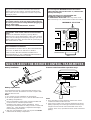
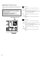
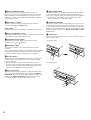
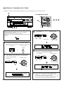
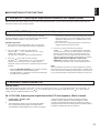
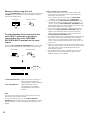
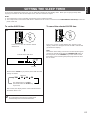
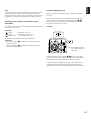
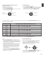
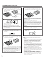
Battery installation
Battery replacement
If you find that the remote control transmitter must be used
closer to the main unit, the batteries are weak. Replace both
batteries with new ones.
Notes
●
Use only AA, R6, UM-3 batteries for replacement.
●
Be sure the polarities are correct. (See the illustration inside
the battery compartment.)
●
Remove the batteries if the remote control transmitter will
not be used for an extended period of time.
●
If batteries leak, dispose of them immediately. Avoid
touching the leaked material or letting it come in contact with
clothing, etc. Clean the battery compartment thoroughly
before installing new batteries.
●
After you change batteries, make sure to press the RESET
button inside the battery compartment.
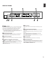
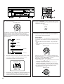
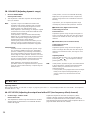
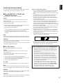
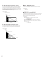
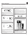
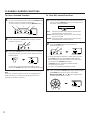
Remote control transmitter operation range
Notes
●
There should be no large obstacles between the remote
control transmitter and the main unit.
●
If the remote control sensor is directly illuminated by strong
lighting (especially an inverter type of fluorescent lamp etc.),
it might cause the remote control transmitter not to work
correctly. In this case, reposition the main unit to avoid direct
lighting.
30°
30°
Remote control
sensor
Within approximately
6 m (19.7 feet)
1
3
2
NOTES ABOUT THE REMOTE CONTROL TRANSMITTER
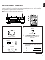
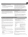
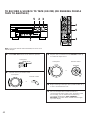
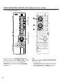
AC OUTLETS
SWITCHED
I00W MAX. TOTAL
200W MAX.
UNSWITCHED
IMPEDANCE SELECTOR
: 4
Ω
MIN. /SPEAKER
A B : 4
Ω
MIN. /SPEAKER
A OR B : 4
Ω
MIN. /SPEAKER
: 4
Ω
MIN. /SPEAKER
EFFECT : 6
Ω
MIN. /SPEAKER
SET BEFORE POWER ON
MAIN
CENTER
REAR
FRONT
: 8
Ω
MIN. /SPEAKER
A B : 4
Ω
MIN. /SPEAKER
A OR B : 8
Ω
MIN. /SPEAKER
: 8
Ω
MIN. /SPEAKER
EFFECT : 8
Ω
MIN. /SPEAKER
MAIN
CENTER
REAR
FRONT
A B
A OR B
+
FRONT REAR
(SURROUND)
VOLTAGE SELECTOR
IMPEDANCE SELECTOR
(General model)

5
English
PROFILE OF THIS UNIT
This unit incorporates a sophisticated, multi-program digital
sound field processor. The processor allows you to
electronically expand and change the shape of the audio sound
field from both audio and video sources, creating a theater-like
experience in your listening room. This unit has a total of 12
digital sound field processor (DSP) modes. You can create an
excellent audio sound field by selecting a suitable sound field
(this will, of course, depend on what you will be listening to),
and adding desired adjustments.
In addition, this unit incorporates a Dolby Pro Logic Surround
decoder and Dolby Digital (AC-3) decoder for multi-channel
sound reproduction of Dolby Surround encoded video sources,
and a DTS decoder for multi-channel sound reproduction of DTS-
encoded audio and video sources. The operation of the Dolby
Pro Logic Surround, Dolby Digital (AC-3) or DTS decoder can be
controlled by selecting a corresponding DSP program including
combined operations of DSP and Dolby Pro Logic Surround, DSP
and Dolby Digital (AC-3), or DSP and DTS.
This unit also features a built-in automatic input balance
control. This always assures you the best performance without
manual adjustment.
Digital Sound Field Processing
What is it that makes live music so good? Today’s advanced
sound reproduction technology lets you get extremely close to
the sound of a live performance, but chances are you’ll still
notice something missing, the acoustic environment of the live
concert hall. Extensive research into the exact nature of the
sonic reflections that create the ambience of a large hall has
made it possible for Yamaha engineers to bring you this same
sound in your own listening room, so you’ll feel all the sound of
a live concert.
Furthermore, our technicians, armed with sophisticated
measuring equipment, have even made it possible to capture
the acoustics of a variety of actual concert halls, jazz clubs,
theaters, etc. from around the world, to allow you to accurately
recreate any one of these live performance environments, all in
your own home.
Dolby Pro Logic Surround
This unit employs a Dolby Pro Logic Surround decoder similar
to professional Dolby Stereo decoders used in many movie
theaters. By using the Dolby Pro Logic Surround decoder, you
can experience the dramatic realism and impact of Dolby
Stereo theater sound in your own home.
Dolby Pro Logic employs a four-channel-five-speaker system.
The Pro Logic Surround system divides the input signal into
four levels: the left and right main channels, the center channel
(used for dialog), and the rear surround sound channel (used
for sound effects, background noise, and other ambient
noises). The center channel allows listeners seated in even
less-than-ideal positions to hear the dialog originating from the
action on the screen while experiencing good stereo imaging.
Dolby Surround is encoded on a lot of sound tracks of pre-
recorded video tapes, laserdiscs, and some TV/cable
broadcasts. When you play a source encoded with Dolby
Surround on this unit, the Dolby Pro Logic Surround decoder
decodes the signal and distributes the surround-sound effects.
Dolby Digital (AC-3)
Dolby Digital (AC-3) is a new generation of Dolby Surround
sound system which is a spatial sound processing format
developed for 35 mm film-movies by employing low bit-rate
audio coding.
Dolby Digital (AC-3) is a digital surround sound system that
provides completely independent multi-channel audio to
consumers. In multi-channel form, Dolby Digital (AC-3)
provides five full range channels in what is sometimes referred
to as a “3/2” configuration: three front channels (left, center and
right), plus two surround channels. A sixth bass-only effect
channel is also provided for output of LFE (low frequency
effect), or low bass effects that are independent of other
channels. (This is called the “subwoofer channel” or “LFE
channel”.) This channel is counted as 0.1, thus giving rise to
the term 5.1 channels in total.
Compared to Dolby Pro Logic that is referred to a “3/1” system
(left front, center, right front and just one surround channel),
Dolby Digital (AC-3) features two surround channels, called
stereo or split surrounds, each offering the same full range
fidelity as the three front channels.
By using the built-in Dolby Digital (AC-3) decoder, you can
experience the dramatic realism and impact of Dolby Stereo
Digital theater sound in your own home.
Sound of wide dynamic range reproduced by the five full range
channels presents listeners much excitement that has never
been experienced before. Precise sound orientation by the
discrete digital sound processing expands realism that the
original movie possesses.

The DTS (Digital Theater Systems) system was developed to
replace analog soundtracks of movies with six discrete
channels of digital soundtracks, and now, it is installed in many
theaters around the world. The DTS digital playback system
changed the way we experienced movies in theaters with six
discrete channels of superb digital audio.
The DTS technology, through intense research and
development, made it possible to deliver a similar
encode/decode discrete technology to home audio surround-
sound entertainment.
The DTS Digital Surround is an encode/decode system which
delivers six channels of master-quality, 20-bit audio; technically
5.1 channels, which means 5 full-range (left, center, right and
two surround) channels, plus a subwoofer (LFE) channel (as
“0.1”). It is compatible with the 5.1 speaker configurations that
are currently available for home theater systems
The DTS Digital Surround algorithm is designed to encode the
six channels of 20-bit audio onto any laserdisc or compact disc
(or DVD in the near future) with considerably less data-
compression.
By using the DTS decoder built into this unit, you can
experience the dramatic realism and impact of the DTS
installed theater’s high quality sound in your own home.
Laserdisc and compact disc (and DVD in the near future) are
home audio format within which DTS can represent its high
quality multi-channel audio. (In addition to movies on
laserdiscs, many exciting new multi-channel music recordings
will also become available in the form of DTS-encoded
compact discs.)
Manufactured under license from DTS Technology LLC.
Additionally licensed under the following US Patent 5,451,942
& National Patent applications derived from PCT/US95/00959.
Additional U.S. and Foreign Patents pending. “DTS”, “digital
surround”, and “coherent acoustics” logos are trademarks of
DTS Technology LLC. All rights reserved.
6
Dolby Digital (AC-3) forms 5.1 channels as mentioned on the
previous page, and moreover, it can also form fewer channels,
for example 2 channel stereo and monaural. You may be able
to find some 2 channel stereo and/or monaural sources
encoded with the Dolby Digital (AC-3) in a market.
If a 2 channel stereo source encoded with the Dolby Digital
(AC-3) is played back as the input source and the DSP
program No. 10, 11 or 12 is used at the same time, the source
is first decoded with the Dolby Digital (AC-3) decoder into 2
channels, and then decoded with the Dolby Pro Logic decoder.
In such a case, only the decoding of Dolby Pro Logic is shown
on the display panel of this unit.
Laserdisc and DVD are home audio formats that could benefit
from Dolby Digital (AC-3). In the near future, Dolby Digital (AC-
3) will also be applied to DBS, CATV and HDTV. The ongoing
release of Dolby Stereo Digital theatrical films now underway
will provide an immediate source of Dolby Digital (AC-3)
encoded video software.
Manufactured under license from Dolby Laboratories Licensing
Corporation. “Dolby”, “AC-3”, “Pro Logic”, and the double-D
symbol are trademarks of Dolby Laboratories Licensing
Corporation.
Copyright 1992 Dolby Laboratories, Inc. All rights reserved.
DTS Digital Surround

7
English
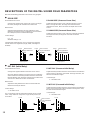
Dolby Pro Logic + 2 Digital Sound Fields
Digital sound fields are created on the presence side and
the rear surround side of the Dolby Pro Logic Surround-
decoded sound field respectively. They create a wide
acoustic environment and emphasize surround-effect in the
room, letting you feel much presence as if you were
watching a movie in a popular Dolby Stereo theater.
This combination is available when the digital sound field
program No. 7, 8, 9, 10, 11 or “PRO LOGIC/Enhanced” of
No. 12 is selected, and the input signal of source is analog,
PCM audio or encoded with the Dolby Digital (AC-3) in 2-
channels.
Dolby Digital (AC-3) or DTS + 3 Digital Sound
Fields
Digital sound fields are created on the presence side and
the independent left and right surround sides of the Dolby
Digital (AC-3)-decoded or the DTS-decoded sound field
respectively. They create a wide acoustic environment and
much surround effect in the room without losing high
channel separation. With wide dynamic range of Dolby
Digital (AC-3) or DTS sound, this sound field combination
lets you feel as if you were watching a movie in the newest
Dolby Stereo Digital theater or DTS installed theater. This
will be the most ideal home theater sound at the present
time.
This combination is available when the digital sound field
program No. 7, 8, 9, 10, 11 or “DOLBY DIGITAL (or DTS
DIGITAL SUR.)/Enhanced” of No. 12 is selected, and the
input signal of source is encoded with the Dolby Digital (AC-
3) (except in 2-channels) or encoded with the DTS.
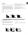
CINEMA DSP: Dolby Surround + DSP / DTS + DSP
Dolby Surround sound system and DTS system show their full
ability in a large movie theater, because movie sounds are
originally designed to be reproduced in a large movie theater
using many speakers. It is difficult to create a sound
environment similar to that of a movie theater in your listening
room, because the room size, materials of inside walls, the
number of speakers, etc. of your listening room are much
different from those of a movie theater.
Yamaha DSP technology made it possible to present you with
nearly the same sound experience as that of a large movie
theater in your listening room by compensating for lack of
presence and dynamics in your listening room with its original
digital sound fields combined with Dolby Surround sound or
DTS Digital Surround sound.
The YAMAHA “CINEMA DSP” logo indicates those programs
are created by the combination of YAMAHA DSP technology
and Dolby Surround or DTS.
CINEMA DSP

8
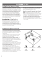
This unit has been designed to provide the best sound field
quality with a full seven-speaker system setup, using a pair of
main speakers to output main source sounds, two extra pairs
of effect speakers to generate the sound field plus one center
speaker for dialog. We therefore recommend that you use a
seven-speaker setup. A four-speaker system using only one
pair of effect speakers for the sound field will still provide
impressive ambience and effects, however, and may be a
good way to begin with this unit. You can always upgrade to
the full seven-speaker system later. In the 4 or 5 speaker
system, the Digital Sound Field Processing is still performed,
but the main speakers are used for both the main channels
and the front effect channels.
Use of the Center Dialog Speaker Is
Recommended
When playing back a source with the Dolby Pro Logic
decoded, or playing back a source which contains center-
channel signals with the Dolby Digital (AC-3) or the DTS
decoded, dialog, vocals etc. are output from the center
channel. Therefore, if you want to maximize the performance
of your Audio/Video home theater system, it is recommended
that you use a center channel speaker.
If for some reason it is not practical to use a center speaker, it
is possible to enjoy movie viewing without it. Best results,
however, are obtained with the full system.
Use of a Subwoofer Expands Your Sound
Field
It is also possible to further expand your system with the
addition of a subwoofer and amplifier. The use of a subwoofer
is effective not only for reinforcing bass frequencies from any
or all channels, but also for reproducing signals at the
subwoofer channel with high fidelity during playing back a
source with the Dolby Digital (AC-3) or the DTS decoded. You
may wish to choose the convenience of a Yamaha Active
Servo Processing Subwoofer System, which has its own built-
in power amplifier.
SPEAKER SETUP
Speakers and Speaker Placement
Your full seven-speaker system will require three speaker
pairs: the MAIN SPEAKERS (your normal stereo speakers),
the FRONT EFFECT SPEAKERS and the REAR SPEAKERS,
plus the CENTER SPEAKER. You may also be using a
SUBWOOFER.
The MAIN SPEAKERS should be high performance models
and have enough power handling capacity to accept the
maximum output of your audio system.
Other speakers do not have to be equal to the MAIN
SPEAKERS. For precise sound localization, however, it is
ideal to use high performance models that can reproduce
sounds in full range for the CENTER SPEAKER, the FRONT
EFFECT and REAR SPEAKERS.
Place the MAIN SPEAKERS in the normal position.
Place the FRONT EFFECT SPEAKERS further apart than the
MAIN SPEAKERS, on either side of and 0.5–1m behind and
above the MAIN SPEAKER pair.
Place the REAR SPEAKERS behind your listening position.
They should be nearly 1.8m up from the floor.
Place the CENTER SPEAKER precisely between the two
MAIN SPEAKERS. (To avoid interference, keep the speaker
above or below the television monitor, or use a magnetically
shielded speaker.)
If using a SUBWOOFER, such as a Yamaha Active Servo
Subwoofer System, the position of the speaker is not so critical
because low bass tones are not highly directional.
Setting Up Your Speaker System
Main speaker
Front effect speaker
Center speaker
Rear speaker
Subwoofer

9
English
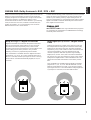
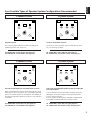
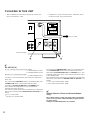
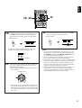
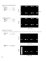
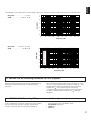
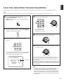
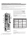
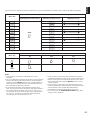
4 Speaker System
Simplest system.
You can enjoy widely diffused sound by only adding two
additional speaker units at the rear.
1E. FRONT MIX—Set to ON-5ch. (See page 27.)
1A. CENTER SP—Set to NONE. (See page 26.)
6 Speaker System
Good for sound fields from 2-channel stereo sources.
When a normal stereo source is played back with the sound
field programs No. 1 through No. 6, a sound effect matching
that of a 7-speaker system can be obtained. The addition of
front left and right effect speakers produces a more effective
sound field.
1E. FRONT MIX—Set to OFF-7ch. (See page 27.)
1A. CENTER SP—Set to NONE. (See page 26.)
5 Speaker System
Good for Audio/Video sources.
By the use of center speaker, center sounds (dialog, vocals
etc.) are precisely localized.
1E. FRONT MIX—Set to ON-5ch. (See page 27.)
1A. CENTER SP—Set to LRG or SML. (See page 26.)
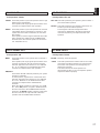
7 Speaker System
This is the recommended speaker system, providing the
best sound effects.
The rear speakers and the front effect speakers produces a
360-degree sound field, and the center speaker provides
precise center localization.
You can experience the amazing YAMAHA “CINEMA DSP”
sound fields completely with the 7 speaker system.
1E. FRONT MIX—Set to OFF-7ch. (See page 27.)
1A. CENTER SP—Set to LRG or SML. (See page 26.)
Four Possible Types of Speaker System Configurations Recommended

10
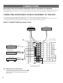
CONNECTIONS
Never plug in this unit and other components until all connections are completed.
When making connections between this unit and other components, be sure all connections are made correctly, that is to say L (left)
to L, R (right) to R, “+” to “+” and “–” to “–”. Also, refer to the owner’s manual for each component to be connected to this unit.
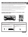
CONNECTING AUDIO/VIDEO SOURCE EQUIPMENT TO THIS UNIT
For connections with audio/video units, use RCA type pin plug cables with the exception described later.
* If you have YAMAHA audio/video units numbered as 1, 2, 3, etc. on the rear panel, connections can be made easily only by
connecting the output (or input) terminals of each unit to the same-numbered terminals of this unit.
MAIN
FRONT
LD
VIDEO S VIDEO
TV/DBS
IN
VCR 1
OUT
IN
VCR 2
OUT
IN
DVD/
VCR 3
OUT
MONITOR
OUT
DVD/VCR 3 OUT
CAN BE USED AS A SECOND
MONITOR OUT, IF SELECTED
BY SET MENU.
VIDEO SIGNALAUDIO SIGNALAUDIO SIGNAL
GND
PHONO
1
CD
2
TUNER
3
PLAY
4
REC
MD/TAPE 1
3
PLAY
4
REC
TAPE 2
EXTERNAL DECODER INPUT
MAIN
SUB
WOOFER
CENTER
SURROUND
CD
TV/DBS
DVD/
VCR 3
COAXIAL
OPTICAL
CD
PLAY
REC
MD/TAPE 1
LD
TV/DBS
DVD/
VCR 3
DIGITAL SIGNAL
PAL NTSC
OUTPUT
GND
OUTPUT
OUTPUT
LINE OUT
LINE IN
LINE OUT
LINE IN
LD
DIGITAL
(AC-3) RF SIGNAL
(General model)
Tuner
Turntable
MD recorder,
Tape deck 1, etc.
CD player
Tape deck 2
BASIC CONNECTIONS (for Audio Units)
GND terminal (For turntable use)
Connecting the ground wire of the turntable to the GND
terminal will normally minimize hum, but in some cases
better results may be obtained with the ground wire
disconnected.
*
1
:
*
1

11
English
(General model)
LD player
Monitor TV
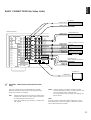
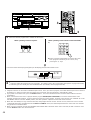
BASIC CONNECTIONS (for Video Units)
Video cassette recorder 2
DVD player or
video cassette recorder 3
MAIN
FRONT
LD
VIDEO S VIDEO
TV/DBS
IN
VCR 1
OUT
IN
VCR 2
OUT
IN
DVD/
VCR 3
OUT
MONITOR
OUT
DVD/VCR 3 OUT
CAN BE USED AS A SECOND
MONITOR OUT, IF SELECTED
BY SET MENU.
VIDEO SIGNALAUDIO SIGNALAUDIO SIGNAL
GND
PHONO
1
CD
2
TUNER
3
PLAY
4
REC
MD/TAPE 1
3
PLAY
4
REC
TAPE 2
EXTERNAL DECODER INPUT
MAIN
SUB
WOOFER
CENTER
SURROUND
LD
CD
TV/DBS
DVD/
VCR 3
COAXIAL
OPTICAL
DIGITAL
(AC-3) RF SIGNAL
CD
PLAY
REC
MD/TAPE 1
LD
TV/DBS
DVD/
VCR 3
DIGITAL SIGNAL
PAL NTSC
VIDEO IN
AUDIO IN
VIDEO IN
AUDIO OUT
VIDEO OUT
AUDIO IN
VIDEO IN
AUDIO OUT
VIDEO OUT
AUDIO IN
VIDEO IN
AUDIO OUT
VIDEO OUT
VIDEO OUT
AUDIO OUT
VIDEO OUT
AUDIO OUT
*
2
Video cassette recorder 1
TV/Satellite tuner
PAL/NTSC switch (China and General models
only)
This unit is designed for use with the NTSC and PAL
television formats. Set this switch to the position for the
format your monitor TV employs.
PAL: Outputs signals in the PAL format no matter which
format (PAL or NTSC) of video signal is sent from
an external video unit to this unit.
Set to this position if your monitor TV employs the
PAL format.
NTSC: Outputs signals in the NTSC format no matter
which format (PAL or NTSC) of video signal is sent
from an external video unit to this unit.
Set to this position if your monitor TV employs the
NTSC format.
Note
Be sure to input a video signal which employs the same
format that your monitor TV employs, otherwise a picture
will not be played back normally.
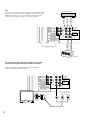
*
2
:

12
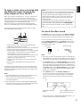
For connecting with a monitor TV that uses a 21 pin
connector for input (for Europe and U.K. models)
Make a connection as figured below with a commercially
available scart-plug connector cable.
VCR 2
OUT
IN
DVD/
VCR 3
OUT
MONITOR
OUT
DVD/VCR 3 OUT
CAN BE USED AS A SECOND
MONITOR OUT, IF SELECTED
BY SET MENU.
3
PLAY
4
REC
TAPE 2
EXTERNAL DECODER INPUT
MAIN
SUB
WOOFER
CENTER
SURROUND
PLAY
REC
MD/TAPE 1
LD
TV/DBS
DVD/
VCR 3
DIGITAL SIGNAL
VIDEO
AUDIO L
AUDIO R
Monitor TV
No connection
Scart-plug connector cable
Note
If you wish to connect a second monitor TV (or a projector) to this
unit, you can switch the DVD/VCR 3 VIDEO OUT terminal (and S
VIDEO terminal also) to a second monitor out terminal for the
connection with another monitor TV. (Refer to page 38.)
VCR 2
OUT
IN
DVD/
VCR 3
OUT
MONITOR
OUT
DVD/VCR 3 OUT
CAN BE USED AS A SECOND
MONITOR OUT, IF SELECTED
BY SET MENU.
3
PLAY
4
REC
TAPE 2
EXTERNAL DECODER INPUT
MAIN
SUB
WOOFER
CENTER
SURROUND
PLAY
REC
MD/TAPE 1
LD
TV/DBS
DVD/
VCR 3
DIGITAL SIGNAL
AUDIO OUT
S-VIDEO OUT
VIDEO OUT
S-VIDEO IN
VIDEO IN
DVD player, etc.
Projector

13
English
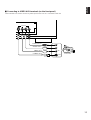
m Connecting to VIDEO AUX terminals (on the front panel)
These terminals are used to connect any video input source such as a camcorder to this unit.
VIDEO AUX
S VIDEO
L
R
VIDEO
VIDEO OUT
S VIDEO OUT
AUDIO OUT L
AUDIO OUT R
Camcorder

14
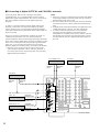
m Connecting to digital (OPTICAL and COAXIAL) terminals
If your CD player, MD recorder, LD player, DVD player,
TV/satellite tuner, etc. are equipped with coaxial or optical
digital audio signal output terminals, they can be connected to
this unit’s COAXIAL and/or OPTICAL digital signal input
terminals.
To make a connection between optical digital audio signal
terminals, remove the cover from each terminal, and then
connect them by using a commercially available optical fiber
cable that conforms to EIAJ standards. Other cables might not
function correctly.
Even if you connect an audio/video unit to the OPTICAL (or
COAXIAL) terminal of this unit, you must keep the unit
connected with the same named analog audio signal terminals
of this unit, because digital signal cannot be recorded by a tape
deck or VCR connected to only analog audio signal terminals
of this unit. You can switch the selection of input signals
between “digital” and “analog” easily. (See page 41 for details.)
* However, if you connect an MD recorder or DAT to this
unit’s OPTICAL MD/TAPE 1 PLAY and REC terminals, it
can record input sources connected to this unit’s OPTICAL
digital signal input terminals.
Notes
●
When you connect an audio/video unit to both of the digital
and analog terminals of this unit, make sure to connect to
both terminals of the same name.
●
Be sure to attach the covers when the OPTICAL terminals
are not being used, in order to protect the terminals from
dust.
●
All digital audio signal input terminals are applicable to the
sampling frequency of 32 kHz, 44.1 kHz and 48 kHz.
●
In order to make this unit perform a successful DTS-
decoding, the DTS bitstream must not be altered,
manipulated or corrupted in the process that it is sent from
the DIGITAL OUT terminal of a unit playing back a source
encoded with the DTS to a digital signal input terminal of
this unit.
MAIN
FRONT
LD
VIDEO S VIDEO
TV/DBS
IN
VCR 1
OUT
IN
VCR 2
OUT
IN
DVD/
VCR 3
OUT
MONITOR
OUT
DVD/VCR 3 OUT
CAN BE USED AS A SECOND
MONITOR OUT, IF SELECTED
BY SET MENU.
VIDEO SIGNALAUDIO SIGNALAUDIO SIGNAL
GND
PHONO
1
CD
2
TUNER
3
PLAY
4
REC
MD/TAPE 1
3
PLAY
4
REC
TAPE 2
EXTERNAL DECODER INPUT
MAIN
SUB
WOOFER
CENTER
SURROUND
CD
TV/DBS
DVD/
VCR 3
COAXIAL
OPTICAL
CD
PLAY
REC
MD/TAPE 1
LD
TV/DBS
DVD/
VCR 3
DIGITAL SIGNAL
PAL NTSC
OPTICAL
DIGITAL
OUT
OPTICAL
DIGITAL OUT
OPTICAL
DIGITAL OUT
COAXIAL
DIGITAL OUT
OPTICAL
DIGITAL IN
COAXIAL
DIGITAL
OUT
OPTICAL
DIGITAL
OUT
OPTICAL
DIGITAL
OUT
COAXIAL
DIGITAL
OUT
LD
DIGITAL
(AC-3) RF SIGNAL
DVD player, etc.
MD recorder,
DAT, etc.
CD player
TV/Satellite tuner LD player
(General model)

15
English
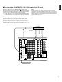
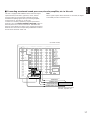
If your LD player has a DOLBY DIGITAL (AC-3) RF signal
output terminal, connect it to this unit’s DIGITAL (AC-3) RF
SIGNAL input terminal. Audio signals encoded with the Dolby
Digital (AC-3) are input to this unit by this connection.
* To play back an LD source with the Dolby Digital decoded,
set the input mode of LD to “AUTO” or “AC-3 RF”. (Refer to
page 41 for details.)
It is also necessary to connect the LD player to this unit’s
OPTICAL digital audio signal input terminal and/or analog
audio signal input terminals regardless of the DOLBY DIGITAL
(AC-3) RF signal connection, for playing back an LD source
with the Dolby Pro Logic Surround or the DTS decoded, or in
normal stereo (or monaural).
Note
DOLBY DIGITAL (AC-3) RF audio input signal cannot be
recorded by a tape deck, MD recorder or VCR. To record an
LD source, the LD player must be connected to the OPTICAL
digital audio signal input terminal and/or analog audio signal
input terminals of this unit.
m Connecting to DOLBY DIGITAL (AC-3) RF output of the LD player
MAIN
FRONT
LD
VIDEO S VIDEO
TV/DBS
IN
VCR 1
OUT
IN
VCR 2
OUT
IN
DVD/
VCR 3
OUT
MONITOR
OUT
DVD/VCR 3 OUT
CAN BE USED AS A SECOND
MONITOR OUT, IF SELECTED
BY SET MENU.
VIDEO SIGNALAUDIO SIGNALAUDIO SIGNAL
GND
PHONO
1
CD
2
TUNER
3
PLAY
4
REC
MD/TAPE 1
3
PLAY
4
REC
TAPE 2
EXTERNAL DECODER INPUT
MAIN
SUB
WOOFER
CENTER
SURROUND
LD
CD
TV/DBS
DVD/
VCR 3
COAXIAL
OPTICAL
CD
PLAY
REC
MD/TAPE 1
LD
TV/DBS
DVD/
VCR 3
DIGITAL SIGNAL
PAL NTSC
DIGITAL OUT
AUDIO OUT
VIDEO OUT
S-VIDEO OUT
DOLBY DIGITAL
(AC-3) RF
OUTPUT
DIGITAL
(AC-3) RF SIGNAL
LD player
(General model)

LD
VIDEO S VIDEO
TV/DBS
IN
VCR 1
OUT
IN
VCR 2
OUT
IN
DVD/
VCR 3
OUT
MONITOR
OUT
DVD/VCR 3 OUT
CAN BE USED AS A SECOND
MONITOR OUT, IF SELECTED
BY SET MENU.
VIDEO SIGNALAUDIO SIGNAL
S-VIDEO
OUT
VIDEO
OUT
VIDEO
OUT
S-VIDEO
OUT
VIDEO
OUT
S-VIDEO OUT
VIDEO IN
S-VIDEO IN
VIDEO IN
S-VIDEO IN
VIDEO OUT
S-VIDEO OUT
S-VIDEO IN
VIDEO IN
VIDEO OUT
S-VIDEO OUT
VIDEO IN
S-VIDEO IN
16
m Connecting to S VIDEO terminals
If your video cassette recorder, LD player, etc. and your
monitor are equipped with “S” (high-resolution) video terminals,
connect them to this unit’s S VIDEO terminals, and connect
this unit’s S VIDEO MONITOR OUT terminal to the “S” video
input of your monitor. Otherwise, connect the composite video
terminals from your video cassette recorder, LD player, etc. to
the VIDEO terminals of this unit, and connect this unit’s VIDEO
MONITOR OUT terminal to the composite video input of your
monitor.
Note
If video signals are sent to both S VIDEO input and VIDEO
input terminals, the signals will be sent to their respective
output terminals.
Notes about the Video superimpose
●
If you watch a video source that is connected to both S
VIDEO and VIDEO input terminals of this unit, signals of
screen display information are output from only the S
VIDEO MONITOR OUT terminal.
●
When no video signal is input to either S VIDEO or VIDEO
input terminals of this unit, signals of screen display
information are output from both S VIDEO MONITOR OUT
and VIDEO MONITOR OUT terminals with a color
background.
* For China and General models, if the PAL/NTSC switch
on the rear panel is set to “PAL”, nothing will be output
from either S VIDEO MONITOR OUT or VIDEO
MONITOR OUT terminal in this case.
LD player
DVD player or video
cassette recorder 3
TV/Satellite tuner
Video cassette recorder 1
Video cassette recorder 2
Monitor TV

17
English
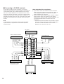
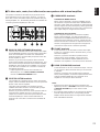
This unit is equipped with additional 6-channel audio signal
input terminals (for left main, right main, center, left rear
surround, right rear surround and subwoofer channels)
available for inputting signals from your existing amplifier,
sound processor, decoder, etc. to this unit.
To listen to a sound by reproducing signals input to these
terminals, press the TAPE 2 MON/EXT. DECODER button on
the front panel once or more so that “EXT. DECODER IN”
appears on the display. By doing so, the signals input to these
terminals are sent to the corresponding SPEAKERS terminals
and OUTPUT terminals of this unit.
Note
When signals input to these terminals are selected, the digital
sound field processor cannot be used.
m Connecting an external sound processor, decoder, amplifier, etc. to this unit
MAIN
FRONT
LD
VIDEO S VIDEO
TV/DBS
IN
VCR 1
OUT
IN
VCR 2
OUT
IN
DVD/
VCR 3
OUT
MONITOR
OUT
DVD/VCR 3 OUT
CAN BE USED AS A SECOND
MONITOR OUT, IF SELECTED
BY SET MENU.
VIDEO SIGNALAUDIO SIGNALAUDIO SIGNAL
GND
PHONO
1
CD
2
TUNER
3
PLAY
4
REC
MD/TAPE 1
3
PLAY
4
REC
TAPE 2
EXTERNAL DECODER INPUT
MAIN
SUB
WOOFER
CENTER
SURROUND
CD
TV/DBS
DVD/
VCR 3
COAXIAL
OPTICAL
CD
PLAY
REC
MD/TAPE 1
LD
TV/DBS
DVD/
VCR 3
DIGITAL SIGNAL
PAL NTSC
SUBWOOFER OUT
SURROUND OUT
CENTER OUT
MAIN OUT
LD
DIGITAL
(AC-3) RF SIGNAL
External sound processor,
decoder, amplifier, etc.
(General model)

18
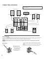
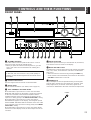
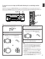
CONNECTING SPEAKERS
SPEAKERS
CAUTION
SEE INSTRUCTION MANUAL FOR CORRECT SETTING.
MAIN
FRONT
CENTER
REAR
(SURROUND)
A B
AB
A OR B
+
PRE
OUT
MAIN
IN
MAIN CH CENTER SUBWOOFER
OUT MONO
OUT IN
FRONT REAR
(SURROUND)
SPLIT
COUPLER
Center speaker
Front effect speakers
Left
Right
Left
Right
Main speakers
Rear speakers
Subwoofer system
Left
Right
Use speakers with the specified impedance shown on the
rear of this unit.
Red: positive (+)
Black: negative (–)
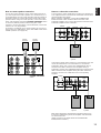
➀
Unscrew the knob.
➁
Insert the bare wire.
[Remove approx. 5mm
(1/4”) insulation from
the speaker wires.]
➂
Tighten the knob and
secure the wire.
<U.S.A., Canada, China, Australia and General models
only
>
Banana Plug connections are also possible. Simply insert the
Banana Plug connector into the corresponding terminal.
1
2
3
How to Connect:
Connect the SPEAKERS terminals to your speakers with wire of the proper gauge, cut as short as possible. If the connections are
faulty, no sound will be heard from the speakers. Make sure that the polarity of the speaker wires is correct, that is the + and –
markings are observed. If these wires are reversed, the sound will be unnatural and lack bass.
Caution
Do not let the bare speaker wires touch each other or any metal part of this unit. This could damage this unit and/or
speakers.
Sidan laddas ...
Sidan laddas ...
Sidan laddas ...
Sidan laddas ...
Sidan laddas ...
Sidan laddas ...
Sidan laddas ...
Sidan laddas ...
Sidan laddas ...
Sidan laddas ...
Sidan laddas ...
Sidan laddas ...
Sidan laddas ...
Sidan laddas ...
Sidan laddas ...
Sidan laddas ...
Sidan laddas ...
Sidan laddas ...
Sidan laddas ...
Sidan laddas ...
Sidan laddas ...
Sidan laddas ...
Sidan laddas ...
Sidan laddas ...
Sidan laddas ...
Sidan laddas ...
Sidan laddas ...
Sidan laddas ...
Sidan laddas ...
Sidan laddas ...
Sidan laddas ...
Sidan laddas ...
Sidan laddas ...
Sidan laddas ...
Sidan laddas ...
Sidan laddas ...
Sidan laddas ...
Sidan laddas ...
Sidan laddas ...
Sidan laddas ...
Sidan laddas ...
Sidan laddas ...
Sidan laddas ...
Sidan laddas ...
Sidan laddas ...
Sidan laddas ...
Sidan laddas ...
Sidan laddas ...
Sidan laddas ...
Sidan laddas ...
Sidan laddas ...
Sidan laddas ...
Sidan laddas ...
Sidan laddas ...
Sidan laddas ...
Sidan laddas ...
Sidan laddas ...
Sidan laddas ...
Sidan laddas ...
Sidan laddas ...
-
 1
1
-
 2
2
-
 3
3
-
 4
4
-
 5
5
-
 6
6
-
 7
7
-
 8
8
-
 9
9
-
 10
10
-
 11
11
-
 12
12
-
 13
13
-
 14
14
-
 15
15
-
 16
16
-
 17
17
-
 18
18
-
 19
19
-
 20
20
-
 21
21
-
 22
22
-
 23
23
-
 24
24
-
 25
25
-
 26
26
-
 27
27
-
 28
28
-
 29
29
-
 30
30
-
 31
31
-
 32
32
-
 33
33
-
 34
34
-
 35
35
-
 36
36
-
 37
37
-
 38
38
-
 39
39
-
 40
40
-
 41
41
-
 42
42
-
 43
43
-
 44
44
-
 45
45
-
 46
46
-
 47
47
-
 48
48
-
 49
49
-
 50
50
-
 51
51
-
 52
52
-
 53
53
-
 54
54
-
 55
55
-
 56
56
-
 57
57
-
 58
58
-
 59
59
-
 60
60
-
 61
61
-
 62
62
-
 63
63
-
 64
64
-
 65
65
-
 66
66
-
 67
67
-
 68
68
-
 69
69
-
 70
70
-
 71
71
-
 72
72
-
 73
73
-
 74
74
-
 75
75
-
 76
76
-
 77
77
-
 78
78
-
 79
79
-
 80
80


Yamaha DSP-1 Användarmanual
- Kategori
- Processorer
- Typ
- Användarmanual
- Denna manual är också lämplig för
på andra språk
- italiano: Yamaha DSP-1 Manuale utente
- čeština: Yamaha DSP-1 Uživatelský manuál
- español: Yamaha DSP-1 Manual de usuario
- Deutsch: Yamaha DSP-1 Benutzerhandbuch
- polski: Yamaha DSP-1 Instrukcja obsługi
- português: Yamaha DSP-1 Manual do usuário
- français: Yamaha DSP-1 Manuel utilisateur
- Türkçe: Yamaha DSP-1 Kullanım kılavuzu
- English: Yamaha DSP-1 User manual
- dansk: Yamaha DSP-1 Brugermanual
- русский: Yamaha DSP-1 Руководство пользователя
- suomi: Yamaha DSP-1 Ohjekirja
- Nederlands: Yamaha DSP-1 Handleiding
- română: Yamaha DSP-1 Manual de utilizare
Relaterade papper
-
Yamaha DSP-A2 Bruksanvisning
-
-
-
Yamaha DSP-A1 Bruksanvisning
-
-
-
-
-
-