
VC002GL
VC004GL
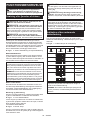
EN Cordless Vacuum Cleaner INSTRUCTION MANUAL 9
SV Batteridriven dammsugare BRUKSANVISNING 23
NO Trådløs støvsuger BRUKSANVISNING 37
FI Akkukäyttöinen pölynimuri KÄYTTÖOHJE 51
DA Akku støvsuger BRUGSANVISNING 64
LV Bezvadu putekļsūcējs LIETOŠANAS INSTRUKCIJA 78
LT Akumuliatorinis vakuuminis
valymo įrenginys NAUDOJIMO INSTRUKCIJA 92
ET Juhtmeta käsitolmuimeja KASUTUSJUHEND 106
RU Аккумуляторный Пылесос РУКОВОДСТВО ПО
ЭКСПЛУАТАЦИИ 119

1
2
3
4
5
Fig.1
2
1
Fig.2
1
2
Fig.3
1
2
Fig.4
1
2
Fig.5
11
2
Fig.6
Fig.7
2

1
3
2
Fig.8
12
3
4
Fig.9
Fig.10
1
2
3
4
5
6
6
6
Fig.11
1
4
2
3
Fig.12
1
2
3
Fig.13
3

1
Fig.14
1
2
Fig.15
Fig.16
1
2
Fig.17
1
2
3
Fig.18
2
3
1
Fig.19
1
2
Fig.20
4

1
2
Fig.21
1
2
34
Fig.22
Fig.23
1
3
2
Fig.24
1
2
3
Fig.25
2
1
Fig.26
Fig.27
1
Fig.28
5

1
2
3
4
Fig.29
1
2
3
Fig.30
1
Fig.31
21
21
Fig.32
Fig.33
1
Fig.34
6

21
Fig.35
1
Fig.36
21
21
Fig.37
32
1
Fig.38
21
Fig.39
1
2
2
Fig.40
1
2
Fig.41
7

Fig.42
Fig.43
1
Fig.44
1
2
Fig.45
Fig.46
8

9ENGLISH
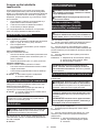
ENGLISH (Original instructions)
WARNING
• This machine is not intended for use by persons including children with reduced physical, sensory or mental
capabilities, or lack of experience and knowledge.
• Children should be supervised to ensure that they do not play with the cleaner.
• See the chapter “SPECIFICATIONS” for the type reference of the battery.
• See the section “Installing or removing battery cartridge” for how to remove or install the battery.
• When disposing the battery cartridge, remove it from the tool and dispose of it in a safe place. Follow your local
regulations relating to disposal of battery.
• If the tool is not used for a long period of time, the battery must be removed from the tool.
• Do not short the battery cartridge.
• See the chapter “MAINTENANCE” for the appropriate details of precautions during user maintenance.
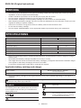
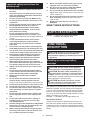
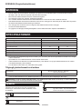
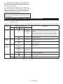
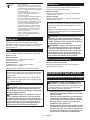
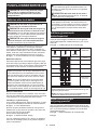
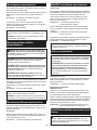
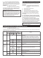
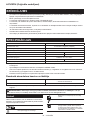
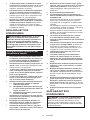
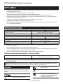
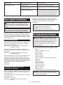
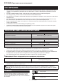
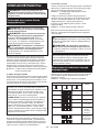
SPECIFICATIONS
Model: VC002GL VC004GL
Standard lter type Powder lter (for dry dust)
Maximum air volume (with BL4040, ø38 mm x 2.5 m hose) 2.7 m3/min
Vacuum (with BL4040, ø38 mm x 2.5 m hose) 23 kPa
Recoverable capacity 8 L 15 L
Dimensions (L x W x H) 366 mm x 334 mm x 425 mm 366 mm x 334 mm x 475 mm
Rated voltage D.C. 36 V - 40 V max
Net weight 8.3 - 10.2 kg 8.6 - 10.5 kg
Protection degree IPX4
• Due to our continuing program of research and development, the specications herein are subject to change
without notice.
• Specications and battery cartridge may dier from country to country.
• The weight does not include accessories but battery cartridge(s). The lightest and heaviest combination weight
of the appliance and battery cartridge(s) are shown in the table.
• For wet dust, the oat and the water lter or cloth lter are required.
Applicable battery cartridge and charger
Battery cartridge BL4020 / BL4025 / BL4040* / BL4050F*
* : Recommended battery
Charger DC40RA / DC40RB / DC40RC
• Some of the battery cartridges and chargers listed above may not be available depending on your region of
residence.
WARNING: Only use the battery cartridges and chargers listed above. Use of any other battery cartridges
and chargers may cause injury and/or re.
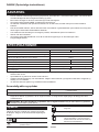
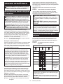
Symbols
The followings show the symbols which may be used
for the equipment. Be sure that you understand their
meaning before use.
Read instruction manual.
Take particular care and attention.
Warning! The cleaner may contain haz-
ardous dust.
Never stand on the cleaner.
Dust class L (light). The cleaners are capa-
ble of picking up dust class L. Follow your
country's regulations relating to dusts and
to occupational health and safety.

10 ENGLISH
Ni-MH
Li-ion
Only for EU countries
Due to the presence of hazardous com-
ponents in the equipment, waste electrical
and electronic equipment, accumulators
and batteries may have a negative impact
on the environment and human health.
Do not dispose of electrical and electronic
appliances or batteries with household
waste!
In accordance with the European Directive
on waste electrical and electronic equip-
ment and on accumulators and batteries
and waste accumulators and batteries,
as well as their adaptation to national law,
waste electrical equipment, batteries and
accumulators should be stored separately
and delivered to a separate collection point
for municipal waste, operating in accor-
dance with the regulations on environmen-
tal protection.
This is indicated by the symbol of the
crossed-out wheeled bin placed on the
equipment.
Intended use
The appliance is intended for collecting dry dust. The
appliance is suitable for commercial use, for example in
hotels, schools, hospitals, factories, shops, oces and
rental businesses.
Noise
The typical A-weighted noise level determined accord-
ing to EN60335-2-69:
Model VC002GL
Sound pressure level (LpA) : 70 dB(A) or less
Uncertainty (K) : 2.5 dB(A)
Model VC004GL
Sound pressure level (LpA) : 70 dB(A) or less
Uncertainty (K) : 2.5 dB(A)
The noise level under working may exceed 80 dB (A).
NOTE: The declared noise emission value(s) has
been measured in accordance with a standard test
method and may be used for comparing one tool with
another.
NOTE: The declared noise emission value(s)
may also be used in a preliminary assessment of
exposure.
WARNING: Wear ear protection.
WARNING: The noise emission during actual
use of the power tool can dier from the declared
value(s) depending on the ways in which the
tool is used especially what kind of workpiece is
processed.
WARNING: Be sure to identify safety mea-
sures to protect the operator that are based on an
estimation of exposure in the actual conditions of
use (taking account of all parts of the operating
cycle such as the times when the tool is switched
o and when it is running idle in addition to the
trigger time).
Vibration
The vibration total value (tri-axial vector sum) deter-
mined according to EN60335-2-69:
Model VC002GL
Vibration emission (ah,M) : 2.5 m/s2 or less
Uncertainty (K) : 1.5 m/s2
Model VC004GL
Vibration emission (ah,M) : 2.5 m/s2 or less
Uncertainty (K) : 1.5 m/s2
NOTE: The declared vibration total value(s) has been
measured in accordance with a standard test method
and may be used for comparing one tool with another.
NOTE: The declared vibration total value(s) may also
be used in a preliminary assessment of exposure.
WARNING: The vibration emission during
actual use of the power tool can dier from the
declared value(s) depending on the ways in which
the tool is used especially what kind of workpiece
is processed.
WARNING: Be sure to identify safety mea-
sures to protect the operator that are based on an
estimation of exposure in the actual conditions of
use (taking account of all parts of the operating
cycle such as the times when the tool is switched
o and when it is running idle in addition to the
trigger time).
EC Declaration of Conformity
For European countries only
The EC declaration of conformity is included as Annex A
to this instruction manual.
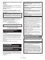
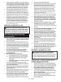
SAFETY WARNINGS
Cordless vacuum cleaner safety
warnings
WARNING: IMPORTANT! READ CAREFULLY
all safety warnings and all instructions BEFORE
USE. Failure to follow the warnings and instructions
may result in electric shock, re and/or serious injury.
1. Before use, make sure that this cleaner must
be used by people who have been adequately
instructed on the use of this cleaner.
2. Before use, operators shall be provided with
information, instruction and training for the
use of the machine and the substances for
which it is to be used, including the safe
method of removal and disposal of the mate-
rial collected.
3. Always make sure that lters are correctly
installed before use. Do not use the cleaner
without lters in place. Replace a damaged
lter immediately. It is recommended to have
some spares as lters are consumable items.

11 ENGLISH
4. AVOID UNINTENTIONAL STARTING. Be sure
switch is OFF when installing battery(ies).
5. Do not attempt to pick up ammable materials,
re works, lighted cigarettes, hot ashes, hot
metal chips, sharp materials such as razors,
needles, broken glass or the like.
6.
NEVER USE THE CLEANER IN THE VICINITY
OF GASOLINE, GAS, PAINT, ADHESIVES OR
OTHER HIGHLY EXPLOSIVE SUBSTANCES.
The switch emits sparks when turned ON and
OFF. And so does the motor commutator during
operation. A dangerous explosion may result.
7. Never vacuum up toxic, carcinogenic, com-
bustible or other hazardous materials such
as asbestos, arsenic, barium, beryllium,
lead, pesticides, or other health endangering
materials.
8. Always place the cleaner on a horizontal at
surface to prevent it from falling or moving
unintentionally.
9. Never use the cleaner outdoors in the rain.
10. For Finland, this machine is not to be used
outdoors at low temperature.
11. Do not use close to heat sources (stoves, etc.).
12. If the exhaust air is returned to the room, it
is necessary to provide for an adequate air
change rate in the room. Reference to National
regulations is necessary.
13. Do not block suction inlet/outlet/cooling vents.
These vents permit cooling of the motor.
Blockage should be carefully avoided other-
wise the motor will burn out due to a lack of
ventilation.
14. Keep proper footing and balance at all times.
15. Do not fold, tug or step on the hose.
16. Stop the cleaner immediately if you notice
poor performance or anything abnormal
during operation.
17. REMOVE THE BATTERY(IES). When not in
use, before servicing, and when changing
accessories.
18. Clean and service the cleaner immediately
after each use to keep it in tiptop operating
condition.
19. MAINTAIN THE CLEANER WITH CARE. Keep
the cleaner clean for better and safer per-
formance. Follow instructions for changing
accessories. Keep handles dry, clean, and free
from oil and grease.
20. CHECK DAMAGED PARTS. Before further use
of the cleaner, a guard or other part that is
damaged should be carefully checked to deter-
mine that it will operate properly and perform
its intended function. Check for alignment of
moving parts, binding of moving parts, break-
age of parts, mounting, and any other condi-
tions that may aect its operation. A guard or
other part that is damaged should be properly
repaired or replaced by an authorized service
center unless otherwise indicated elsewhere
in this instruction manual. Have defective
switches replaced by authorized service cen-
ter. Don’t use the cleaner if switch does not
turn it on and o.
21. For user servicing, the machine shall be dis-
mantled, cleaned and serviced, as far as is
reasonably practicable, without causing risk to
the maintenance sta and others.
22. The machine should be technically inspected
by the manufacturer, or an instructed person,
at least annually, consisting of, for example,
inspection of lters for damage, air tightness
of the machine and proper function of the
control mechanism.
23. When carrying out service or repair opera-
tions, all contaminated items which cannot be
satisfactorily cleaned are to be disposed of;
such items shall be disposed of in impervious
bags in accordance with any current regula-
tion for the disposal of such waste.
24. REPLACEMENT PARTS. When servicing, use
only identical replacement parts.
25.
When not in use, always store the cleaner indoors.
26. Be kind to your cleaner. Rough handling can
cause breakage of even the most sturdily built
cleaner.
27. Do not attempt to clean the exterior or interior
with benzine, thinner or cleaning chemicals.
Cracks and discoloration may be caused.
28. Do not use cleaner in an enclosed space where
ammable, explosive or toxic vapors are given
o by oil-base paint, paint-thinner, gasoline,
some mothproong substances, etc., or in
areas where ammable dust is present.
29. Do not operate the cleaner or any tool while
under the inuence of drugs or alcohol.
30. As a basic rule of safety, use safety goggles or
safety glasses with side shields.
31. Use a dust mask in dusty work conditions.
32. This machine is not intended for use by per-
sons including children with reduced physical,
sensory or mental capabilities, or lack of expe-
rience and knowledge.
33. Children should be supervised to ensure that
they do not play with the cleaner.
34. Never handle battery(ies) and cleaner with wet
hands.
35. Use extreme caution when cleaning on stairs.
36. Do not use the cleaner as a stool or work
bench. The machine may fall down and may
result in personal injury.
37. Do not pick up foam or soapy liquid. It can
cause foam to come out of air exit, resulting in
electric shock and damage to the cleaner.
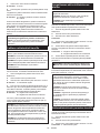
Battery tool use and care
1. Recharge only with the charger specied by
the manufacturer. A charger that is suitable for
one type of battery pack may create a risk of re
when used with another battery pack.
2. Use power tools only with specically desig-
nated battery packs. Use of any other battery
packs may create a risk of injury and re.
3. When battery pack is not in use, keep it away
from other metal objects, like paper clips,
coins, keys, nails, screws or other small metal
objects, that can make a connection from one
terminal to another. Shorting the battery termi-
nals together may cause burns or a re.

12 ENGLISH
4.
Under abusive conditions, liquid may be ejected
from the battery; avoid contact. If contact acci-
dentally occurs, ush with water. If liquid contacts
eyes, additionally seek medical help. Liquid ejected
from the battery may cause irritation or burns.
5. Do not use a battery pack or tool that is dam-
aged or modied. Damaged or modied batteries
may exhibit unpredictable behaviour resulting in
re, explosion or risk of injury.
6. Do not expose a battery pack or tool to re or
excessive temperature. Exposure to re or tem-
perature above 130 °C may cause explosion.
7. Follow all charging instructions and do not
charge the battery pack or tool outside the
temperature range specied in the instruc-
tions. Charging improperly or at temperatures
outside the specied range may damage the
battery and increase the risk of re.
SAVE THESE INSTRUCTIONS.
WARNING: DO NOT let comfort or familiarity
with product (gained from repeated use) replace
strict adherence to safety rules for the subject
product. MISUSE or failure to follow the safety
rules stated in this instruction manual may cause
serious personal injury.
Important safety instructions for
battery cartridge
1.
Before using battery cartridge, read all instruc-
tions and cautionary markings on (1) battery
charger, (2) battery, and (3) product using battery.
2.
Do not disassemble or tamper the battery cartridge.
It may result in a re, excessive heat, or explosion.
3.
If operating time has become excessively shorter,
stop operating immediately. It may result in a risk of
overheating, possible burns and even an explosion.
4.
If electrolyte gets into your eyes, rinse them out
with clear water and seek medical attention right
away. It may result in loss of your eyesight.
5. Do not short the battery cartridge:
(1) Do not touch the terminals with any con-
ductive material.
(2) Avoid storing battery cartridge in a con-
tainer with other metal objects such as
nails, coins, etc.
(3) Do not expose battery cartridge to water
or rain.
A battery short can cause a large current
ow, overheating, possible burns and even a
breakdown.
6. Do not store and use the tool and battery car-
tridge in locations where the temperature may
reach or exceed 50 °C (122 °F).
7. Do not incinerate the battery cartridge even if
it is severely damaged or is completely worn
out. The battery cartridge can explode in a re.
8. Do not nail, cut, crush, throw, drop the battery
cartridge, or hit against a hard object to the
battery cartridge. Such conduct may result in a
re, excessive heat, or explosion.
9. Do not use a damaged battery.
10. The contained lithium-ion batteries are subject
to the Dangerous Goods Legislation require-
ments.
For commercial transports e.g. by third parties,
forwarding agents, special requirement on pack-
aging and labeling must be observed.
For preparation of the item being shipped, consult-
ing an expert for hazardous material is required.
Please also observe possibly more detailed
national regulations.
Tape or mask o open contacts and pack up the
battery in such a manner that it cannot move
around in the packaging.
11. When disposing the battery cartridge, remove
it from the tool and dispose of it in a safe
place. Follow your local regulations relating to
disposal of battery.
12. Use the batteries only with the products
specied by Makita. Installing the batteries to
non-compliant products may result in a re, exces-
sive heat, explosion, or leak of electrolyte.
13. If the tool is not used for a long period of time,
the battery must be removed from the tool.
14. During and after use, the battery cartridge may
take on heat which can cause burns or low
temperature burns. Pay attention to the han-
dling of hot battery cartridges.
15. Do not touch the terminal of the tool imme-
diately after use as it may get hot enough to
cause burns.
16. Do not allow chips, dust, or soil stuck into the
terminals, holes, and grooves of the battery
cartridge. It may result in poor performance or
breakdown of the tool or battery cartridge.
17. Unless the tool supports the use near
high-voltage electrical power lines, do not use
the battery cartridge near a high-voltage elec-
trical power lines. It may result in a malfunction
or breakdown of the tool or battery cartridge.
18. Keep the battery away from children.
SAVE THESE INSTRUCTIONS.
CAUTION: Only use genuine Makita batteries.
Use of non-genuine Makita batteries, or batteries that
have been altered, may result in the battery bursting
causing res, personal injury and damage. It will
also void the Makita warranty for the Makita tool and
charger.
Tips for maintaining maximum
battery life
1. Charge the battery cartridge before completely
discharged. Always stop tool operation and
charge the battery cartridge when you notice
less tool power.
2.
Never recharge a fully charged battery cartridge.
Overcharging shortens the battery service life.
3.
Charge the battery cartridge with room tempera-
ture at 10 °C - 40 °C (50 °F - 104 °F). Let a hot
battery cartridge cool down before charging it.
4. When not using the battery cartridge, remove
it from the tool or the charger.
5. Charge the battery cartridge if you do not use
it for a long period (more than six months).

13 ENGLISH
Important safety instructions for
wireless unit
1. Do not disassemble or tamper with the wire-
less unit.
2. Keep the wireless unit away from young chil-
dren. If accidentally swallowed, seek medical
attention immediately.
3. Use the wireless unit only with Makita tools.
4. Do not expose the wireless unit to rain or wet
conditions.
5. Do not use the wireless unit in places where
the temperature exceeds 50 °C (122 °F).
6. Do not operate the wireless unit in places
where medical instruments, such as heart
pace makers are nearby.
7. Do not operate the wireless unit in places
where automated devices are nearby. If oper-
ated, automated devices may develop malfunction
or error.
8. Do not operate the wireless unit in places
under high temperature or places where
static electricity or electrical noise could be
generated.
9.
The wireless unit can produce electromagnetic
elds (EMF) but they are not harmful to the user.
10. The wireless unit is an accurate instrument. Be
careful not to drop or strike the wireless unit.
11. Avoid touching the terminal of the wireless
unit with bare hands or metallic materials.
12. Always remove the battery on the product
when installing the wireless unit into it.
13. When opening the lid of the slot, avoid the
place where dust and water may come into the
slot. Always keep the inlet of the slot clean.
14. Always insert the wireless unit in the correct
direction.
15. Do not press the wireless activation button
on the wireless unit too hard and/or press the
button with an object with a sharp edge.
16. Always close the lid of the slot when
operating.
17.
Do not remove the wireless unit from the slot
while the power is being supplied to the tool.
Doing so may cause a malfunction of the wireless unit.
18. Do not remove the sticker on the wireless unit.
19. Do not put any sticker on the wireless unit.
20. Do not leave the wireless unit in a place where
static electricity or electrical noise could be
generated.
21. Do not leave the wireless unit in a place sub-
ject to high heat, such as a car sitting in the
sun.
22. Do not leave the wireless unit in a dusty or
powdery place or in a place corrosive gas
could be generated.
23. Sudden change of the temperature may bedew
the wireless unit. Do not use the wireless unit
until the dew is completely dried.
24. When cleaning the wireless unit, gently wipe
with a dry soft cloth. Do not use benzine, thin-
ner, conductive grease or the like.
25. When storing the wireless unit, keep it in the
supplied case or a static-free container.
26. Do not insert any devices other than Makita
wireless unit into the slot on the tool.
27. Do not use the tool with the lid of the slot dam-
aged. Water, dust, and dirt come into the slot may
cause malfunction.
28. Do not pull and/or twist the lid of the slot more
than necessary. Restore the lid if it comes o
from the tool.
29. Replace the lid of the slot if it is lost or
damaged.
SAVE THESE INSTRUCTIONS.
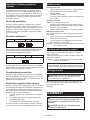
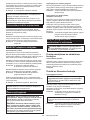
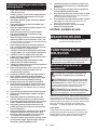
PARTS DESCRIPTION
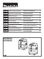
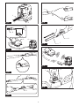
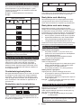
► Fig.1: 1. Head unit 2. Powder lter (HEPA)
3. Damper 4. Prelter 5. Tank
FUNCTIONAL
DESCRIPTION
CAUTION: Always be sure that the appliance
is switched o and the battery cartridges are
removed before adjusting or checking function on
the appliance.
Installing or removing battery
cartridge
CAUTION: Always switch o the appliance
before installing or removing battery cartridges.
CAUTION: Hold the cleaner and battery car-
tridges rmly when installing or removing battery
cartridges. Failure to do so may cause them to slip
o your hands, resulting in damage to the cleaner and
battery cartridges or personal injury.
CAUTION: Be careful not to pinch your n-
gers when opening or closing the battery cover.
Failure to do so may cause personal injury.
The cleaner has double battery slots. With two identical
batteries in parallel, you can extend your running time
in one or more uses without having to stop to recharge
batteries. The cleaner also works with a single battery,
so you can choose with either double batteries or single
battery according to your needs.
► Fig.2: 1. Left battery slot 2. Right battery slot
With double batteries
Continuous drive with two batteries allows longer run-
time and more ecient cleaning. When the rst battery
is becoming empty, the cleaner automatically switches
a power source, so it continues working with the second
battery.

14 ENGLISH
NOTE: The left battery slot (when facing the front of
the cleaner) has priority over the right battery slot.
The right battery slot will only be identied as a power
source, either when no battery is installed in the
left battery slot or the battery in the left battery slot
becomes empty.
NOTE: You can remove the battery from the left
battery slot and recharge it after the cleaner has
switched its power source from the left battery slot to
the right without ceasing operation. To give priority
back to the left battery slot after installing a recharged
battery, restart the cleaner.
With a single battery
Only one battery is required as a power source in either
the left or right battery slot. The cleaner automatically
determines which battery slot is available according to
operating conditions.
Installation and uninstallation
To install battery cartridges, release the lock rst,
and open the battery cover. Then insert the battery
cartridges.
► Fig.3: 1. Lock 2. Battery cover
Align the tongues on the battery cartridges with the
grooves in the battery housing and slip them into place.
Insert them all the way until they lock in place with a
little click.
Then lock the battery cover.
► Fig.4: 1. Battery cartridge 2. Button
To remove the battery cartridges, slide them out of the
battery housing while pressing and holding the buttons
in front of the cartridges.
CAUTION: Always install the battery cartridge
fully. If not, it may accidentally fall out of the appli-
ance, causing injury to you or someone around you.
CAUTION: Do not install the battery cartridge
forcibly. If the cartridge does not slide in easily, it is
not being inserted correctly.
NOTE: When the cleaner switches the power source
from the rst battery to the second, it may require a
temporary halt in operations, causing a slight loss of
suction. Please note that it is not malfunction so the
cleaner recovers and resumes operations immedi-
ately after the pause.
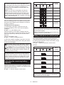
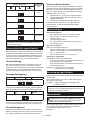
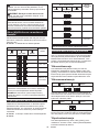
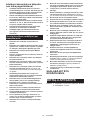
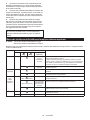
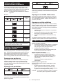
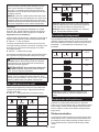
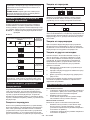
Indicating the remaining battery
capacity
Press the check button on the battery cartridge to indi-
cate the remaining battery capacity. The indicator lamps
light up for a few seconds.
► Fig.5: 1. Indicator lamps 2. Check button
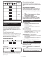
Indicator lamps Remaining
capacity
Lighted O Blinking
75% to 100%
50% to 75%
25% to 50%
0% to 25%
Charge the
battery.
The battery
may have
malfunctioned.
NOTE: Depending on the conditions of use and the
ambient temperature, the indication may dier slightly
from the actual capacity.
NOTE: The rst (far left) indicator lamp will blink when
the battery protection system works.
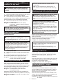
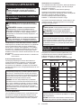
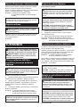
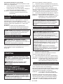
Battery indicators on control panel
The remaining battery capacity can be read on the
control panel at any time. Press the check button, and
the left and right indicators will show the battery charge
levels correspondingly.
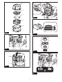
► Fig.6: 1. Battery indicators 2. Check button
► Fig.7
Battery indicator status Remaining
battery
capacity
On O Blinking
50% to 100%
20% to 50%
0% to 20%
Charge the
battery
Battery not
inserted
NOTE: The battery indicators will also be activated
when the cleaner starts functioning or switches its
power source from one to another.

15 ENGLISH
Appliance / battery protection
system
The appliance is equipped with an appliance/battery
protection system. This system automatically cuts o
power to the motor to extend appliance and battery life.
The appliance will automatically stop during operation
if the appliance or battery is placed under one of the
following conditions:
Overload protection
When the appliance/battery is operated in a manner
that causes it to draw an abnormally high current, the
appliance automatically stops. In this situation, turn the
appliance o and stop the application that caused the
appliance to become overloaded. Then turn the appli-
ance on to restart.
Overheat protection
On Blinking
When the appliance is overheated, the appliance stops
automatically, and both left and right battery indicators
blink. In this situation, let the appliance cool down
before turning the appliance on again.
On Blinking
When the battery is overheated, the appliance stops
automatically, and one of the indicators for overheated
battery blinks. In this situation, let the battery cool down
before turning the appliance on again.
Overdischarge protection
When the battery capacity becomes low, the appliance
stops automatically. If the appliance does not run along
with the switch operation, remove the batteries from the
appliance and recharge them.
Protections against other causes
Protection system is also designed for other causes that
could damage the appliance and allows the appliance to
stop automatically. Take all the following steps to clear
the causes, when the appliance has been brought to a
temporary halt or stop in operation.
1. Turn the appliance o, and then turn it on again to
restart.
2. Charge the battery(ies) or replace it/them with
recharged battery(ies).
3. Let the appliance and battery(ies) cool down.
If no improvement can be found by restoring protection
system, then contact your local Makita Service Center.
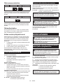
Switch action
Turning cleaner on
1. Turn the stand-by switch in the "I" (ON) or "AUTO"
(ON) position to have the cleaner ready in
stand-by mode.
2. Press the power button.
To switch back to stand-by mode, press the power
button again.
Turning cleaner o
Perform one of the following steps.
• Press the power button to set the cleaner back in
stand-by mode, and then turn the stand-by switch
in the "O" (OFF) position.
• Turn the stand-by switch in the "O" (OFF) position.
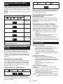
Adjusting suction power
The suction power can be adjusted according to your
work needs.
• Turn the suction force adjusting knob to the left to
reduce the suction power.
• Turn the suction force adjusting knob to the right
to increase the suction power.
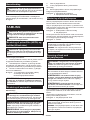
► Fig.8: 1. Stand-by switch 2. Power button 3. Suction
force adjusting knob
Locking and unlocking casters
Rear casters can be locked with stoppers to help the
cleaner stand still.
Lower the stopper lever by hand to lock the caster, and
raise it up to release.
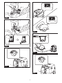
► Fig.9: 1. Caster 2. Stopper lever 3. Unlocked posi-
tion 4. Locked position
NOTE: When moving the cleaner, make sure that the
caster is unlocked. Moving the cleaner with the caster
in a locked position may cause damage to the caster.
Carriage handle
CAUTION: Lift and carry the appliance with
due care. Failing to do so may result in personal
injury or damage to the appliance.
When carrying the cleaner, carry it by holding the han-
dle on the head unit. The handle is retractable on the
head unit when not in use.
► Fig.10
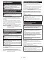
ASSEMBLY
CAUTION: Always be sure that the appliance
is switched o and the battery cartridges are
removed before carrying out any work on the
appliance.
CAUTION: Always wear dust mask during
assembly or maintenance.

16 ENGLISH
Installing powder lter (HEPA) and
prelter (for dry dust)
CAUTION: Never pick up water or other liq-
uids or wet dusts when using the powder lter.
Picking up such things may cause the powder lter
breakage.
To use powder lter:
1. Place the prelter into the tank aligning the mount-
ing position markings on the prelter and tank.
2. Set the damper into the prelter, and then place
the powder lter over the damper aligning the mounting
position markings on the powder lter and prelter.
3. Mount the head unit over the tank and secure
them with the locking latches.
► Fig.11: 1. Head unit 2. Powder lter (HEPA)
3. Damper 4. Prelter 5. Tank 6. Mounting
position marking
NOTICE: Before using the powder lter, make
sure that prelter and damper are used together. It
is not allowed to install powder lter alone.
Installing paper pack
Optional accessory
WARNING: Before using a paper pack, make
sure that the prelter is used together. Failure to
use the prelter together may cause unusual noise
and heat, resulting in a re.
NOTICE: Never pick up water or other liquids
or wet dusts when using a paper pack. Picking up
such things may cause the paper pack breakage.
NOTICE: Before using a paper pack, make sure
that the powder lter, damper and prelter are
always used together.
1. Unfold a paper pack.
2. Align the paper pack opening with the dust intake
of the tank.
3. Install the paper pack into the tank with its card-
board opening hooked on the paper pack holder.
► Fig.12: 1. Paper pack 2. Cardboard opening
3. Paper pack holder 4. Dust intake
Installing polyethylene bag
With a polyethylene bag installed in the tank, you can
easily empty the tank without letting your hands dirty.
Lay a polyethylene bag over the tank, and slip one side
of the top edge of the bag at its open end in between
the holder plate and the front wall of the tank.
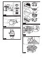
► Fig.13: 1. Holder plate 2. Front wall of tank
3. Polyethylene bag
Spread the other top edges of the bag outwards over
the top rims of the tank. Place the prelter over the poly-
ethylene bag to fasten the opening of the bag securely.
► Fig.14: 1. Prelter
NOTE: A polyethylene bag available on the
market can be used. 0.04 mm or thicker one is
recommended.
NOTE: Too much dust will tear the bag easily, so
do not collect the dust more than the half of the bag
capacity.
Emptying tank with polyethylene bag
WARNING: Always make sure that the cleaner
is switched o and the battery cartridges are
removed before emptying the tank. Failure to do
so may cause an electric shock and serious personal
injury.
NOTICE: Do not apply a great impact on the
tank. Applying a great impact may cause deformation
and damage to the parts.
NOTICE: Empty the tank at least once a day
although this depends on picked-up dust volume
in the tank. Or, the suction force will weaken and the
motor may be broken.
NOTICE: Do not grab the hooks or latches when
emptying the tank. Grabbing the hooks or latches
may cause them to break.
Release the locking latches and lift the head unit up o the tank.
Shake o dust from the prelter before lifting the lter
away from the tank.
Then remove the polyethylene bag out of the tank,
closing the opening of the bag by hand.
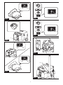
► Fig.15: 1. Polyethylene bag 2. Tank
NOTE: Take the polyethylene bag out of the tank
carefully to avoid it from being scratched and torn by
the edges inside the tank.
NOTE: Empty the polyethylene bag before it
becomes full. Too much dust in the tank may cause
the polyethylene bag to be torn.
Installing multi hook
Use the multi hook to hold a hose, accessories and
attachments not in use in place, and you can quickly
take them out according to your preferences.
► Fig.16
Place the multi hook over the mounting base at the rear
of the cleaner, setting the rails on the multi hook along
the grooves on the mounting base.
► Fig.17: 1. Multi hook 2. Mounting base
Installing MAKPAC adapter
Optional accessory
Connectable and stackable MAKPAC storage cases
can be installed on top of the cleaner with an optional
adapter. The cases are available in many sizes and
styles to suit your preferences.
Place the mounting base hook over the handle of the
cleaner with its mounting surface facing upwards when
the handle is folded into the closed position.
► Fig.18: 1. Mounting base hook 2. Mounting surface
3. Handle

17 ENGLISH
Mount the MAKPAC adapter onto the mounting base
hook, and secure them together with four screws
provided.
► Fig.19: 1. MAKPAC adapter 2. Mounting base hook
3. Screw
Lift the push bar up and tighten the knob to prepare
installing the MAKPAC cases onto the cleaner.
► Fig.20: 1. Push bar 2. Knob
NOTE: For details on installing the MAKPAC cases,
refer to the instructions provided with the MAKPAC
adapter and cases.
Installing hose
NOTICE: Never force the hose for bending or
stamp it. Never move the cleaner by pulling the
hose. Forcing, stamping and pulling the hose may
cause a breakage or deformation of the hose.
NOTICE: When picking up large wastes such as
planer carvings, concrete dusts or similar other
than small wastes, use the 38 mm inner diameter
hose (optional accessory). Using the 28 mm inner
diameter hose (optional accessory) may cause a
hose stung and damage.
Connection to cleaner
Insert the hose end to the dust intake (hose inlet) of the
cleaner, then turn it clockwise until it locks in place.
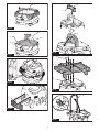
► Fig.21: 1. Hose 2. Dust intake (hose inlet)
Connections with your work tools
(Country specic)
By connecting the vacuum cleaner to any available
work tools compatible with the cleaner, it works as a
dust extractor for your power tools.
Select one of the front cus or joints (optional acces-
sories) as most suitable for your tool model. Place the
cus or joint, as necessary, between the front end of the
cleaner hose and a dust extraction port of your tool.
► Fig.22: 1. Front cus or joint 2. Cleaner hose
3. Power tool 4. Vacuum cleaner
Installing or removing cleaner
attachments
CAUTION: After installing an attachment,
check if it is securely installed. If the attachment
is installed imperfectly, it may come o and cause
personal injury.
Attachments without lock function
Optional accessory
Insert an attachment into the suction inlet of the cleaner
by pushing and hand screwing it in place.
Hand twist and pull the attachment apart from the suc-
tion inlet after use.
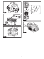
► Fig.23
Attachments with lock function
Optional accessory
NOTICE: When installing the attachment with
lock function, be sure to align the release button
with the hook on the attachment. If they are not
aligned, the attachment will not be locked and may
come o from the cleaner.
Insert an attachment into the suction inlet of the cleaner
by pushing them together with a click.
To remove the attachment, pull it o while pushing the release button.
► Fig.24: 1. Suction inlet with lock function 2. Release
button 3. Attachment with lock function
NOTE: An attachment with lock function can only be
installed in the suction inlet with lock function.
► Fig.25: 1. Attachment with lock function 2. Suction
inlet with lock function 3. Suction inlet with-
out lock function
Adjusting lengths of slide-type
extension wand
Optional accessory
A slide-type extension wand can be combined for
shorter and longer lengths. It allows to clean hard-to-
reach areas and comfortable positioning options.
Pull in and out the slide pipe to change wand lengths
while pressing and holding the slide button.
Release the slide button to lock the slide pipe in your desired position.
► Fig.26: 1. Slide pipe 2. Slide button
WIRELESS ACTIVATION
FUNCTION
What you can do with the wireless
activation function
The wireless activation function enables clean and
comfortable operation. By connecting a supported tool
to the cleaner, you can run the cleaner automatically
along with the switch operation of the tool.
► Fig.27
NOTICE: Be sure to refer to the instruction man-
ual of the tool when using the cleaner with wire-
less activation function.
NOTICE: Do not disassemble or tamper with the
wireless unit.
NOTICE: To prevent dust coming into the slot
of the wireless unit, always close the lid securely
during operation and storage.
NOTICE: Do not remove the wireless unit while
the power is being supplied. Doing so may cause a
malfunction of the wireless unit.
NOTICE: Do not press the wireless activation
button too hard and/or press the button with an
object with a sharp edge.

18 ENGLISH
NOTE: Wireless activation needs Makita tools
equipped with the wireless unit.
NOTE: Prior to the initial use of the wireless activa-
tion function with each tool, the tool registration is
required. Once the registration is nished with the
tool, the re-registration is not required unless it is
cancelled.
NOTE: Before registration, be sure that the wireless
unit is properly inserted.
NOTE: One wireless unit can register up to 10 links
with other wireless units. If more than 10 other wire-
less units are registered to one wireless unit, the one
registered earliest will be cancelled automatically.
NOTE: The position of the wireless activation button
varies depending on the tool.
NOTE: The cleaner also starts by pressing the power
button when the stand-by switch is set to "AUTO".
However the power button will not actuate when the
wireless activation function is used.
Installing the wireless unit
CAUTION: Place the cleaner on a at and
stable surface when installing the wireless unit.
NOTICE: Clean the dust and dirt on the cleaner
before installing the wireless unit. Dust or dirt
may cause malfunction if it comes into the slot of the
wireless unit.
NOTICE: To prevent the malfunction caused by
static, touch a static discharging material, such
as a metallic part, before picking up the wireless
unit.
NOTICE: When installing the wireless unit,
always be sure that the wireless unit is inserted
in the correct direction and the lid is completely
closed.
1. Open the lid on the cleaner as shown in the gure.
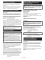
► Fig.28: 1. Lid
2. Insert the wireless unit to the slot and then close
the lid.
When inserting the wireless unit, align the projections
with the recessed portions on the slot.
► Fig.29: 1. Wireless unit 2. Projection 3. Lid
4. Recessed portion
When removing the wireless unit, open the lid slowly.
The hooks on the back of the lid will lift the wireless unit
as you pull up the lid.
► Fig.30: 1. Wireless unit 2. Hook 3. Lid
After removing the wireless unit, keep it in the supplied
case or a static-free container.
NOTICE: Always use the hooks on the back of
the lid when removing the wireless unit. If the
hooks do not catch the wireless unit, close the lid
completely and open it slowly again.
Tool registration for the cleaner
NOTE: A Makita tool supporting the wireless activa-
tion function is required for the tool registration.
NOTE: Finish installing the wireless unit to the tool
before starting the tool registration.
NOTE: During the tool registration, do not pull the
switch trigger on the tool or turn on the power switch
on the cleaner.
NOTE: Refer to the instruction manual of the tool, too.
If you wish to activate the cleaner along with the
switch operation of the tool, nish the tool registration
beforehand.
1. Install the wireless units to the cleaner and the
tool, respectively.
2. Install the batteries to the cleaner and the tool.
3. Set the stand-by switch on the cleaner to "AUTO".
► Fig.31: 1. Stand-by switch
4. Press the wireless activation button on the cleaner
for 3 seconds until the wireless activation lamp blinks in
green. And then press the wireless activation button on
the tool in the same way.
► Fig.32: 1. Wireless activation button 2. Wireless
activation lamp
If the cleaner and the tool are linked successfully, the
wireless activation lamps will light up in green for 2
seconds and start blinking in blue.
NOTE: The wireless activation lamps nish blinking
in green after 20 seconds elapsed. Press the wireless
activation button on the tool while the wireless acti-
vation lamp on the cleaner is blinking. If the wireless
activation lamp does not blink in green, push the wire-
less activation button briey and hold it down again.
NOTE: When performing two or more tool registration
for the cleaner, nish the tool registration one by one.
Starting the wireless activation
function
NOTE: Finish the tool registration for the cleaner for
wireless activation.
NOTE: Always place the cleaner so that you can see
the status of the wireless activation lamp.
NOTE: Refer to the instruction manual of the tool, too.
After registering a tool to the cleaner, the cleaner will
automatically runs along with the switch operation of
the tool.
1. Install the wireless units to the cleaner and the
tool, respectively.
2. Install the batteries to the cleaner and the tool.
3. Connect the hose of the cleaner with the tool.
► Fig.33
4. Set the stand-by switch on the cleaner to "AUTO".
► Fig.34: 1. Stand-by switch

19 ENGLISH
5. Push the wireless activation button on the tool
briey. The wireless activation lamp will blink in blue.
► Fig.35: 1. Wireless activation button 2. Wireless
activation lamp
6. Pull the switch trigger of the tool. Check if the
cleaner runs while the switch trigger on the tool is being
pulled.
CAUTION: Always check if the wireless acti-
vation function works before starting a work with
the tool.
To stop the wireless activation, push the wireless activa-
tion button on the tool, or set the stand-by switch on the
cleaner to "I" or "O".
NOTE: The wireless activation lamp on the tool will
stop blinking in blue when there is no operation for
2 hours. In this case, set the stand-by switch on the
cleaner to "AUTO" and press the wireless activation
button on the tool again.
NOTE: The cleaner starts/stops with a delay. There is
a time lag when the cleaner detects a switch opera-
tion of the tool.
NOTE: The transmission distance of the wireless unit
may vary depending on the location and surrounding
circumstances.
NOTE: When two or more tools are registered to one
cleaner, the cleaner may start running even if you
don't pull the switch trigger because other user is
using the wireless activation function.
Cancelling tool registration for the
cleaner
Perform the following procedure when cancelling the
tool registration for the cleaner.
1. Install the wireless units to the cleaner and the
tool, respectively.
2. Install the batteries to the cleaner and the tool.
3. Set the stand-by switch on the cleaner to "AUTO".
► Fig.36: 1. Stand-by switch
4. Press the wireless activation button on the cleaner
for 6 seconds. The wireless activation lamp blinks in
green and then become red. After that, press the wire-
less activation button on the tool in the same way.
► Fig.37: 1. Wireless activation button 2. Wireless
activation lamp
If the cancellation is performed successfully, the wire-
less activation lamps will light up in red for 2 seconds
and start blinking in blue.
NOTE: The wireless activation lamps nish blinking in
red after 20 seconds elapsed. Press the wireless acti-
vation button on the tool while the wireless activation
lamp on the cleaner is blinking. If the wireless acti-
vation lamp does not blink in red, push the wireless
activation button briey and hold it down again.
Erasing all tool registrations
You can erase all tool registrations from the cleaner as
follows.
► Fig.38: 1. Stand-by switch 2. Wireless activation
button 3. Wireless activation lamp
1. Install the wireless unit to the cleaner.
2. Install the batteries to the cleaner.
3. Set the stand-by switch to "AUTO".
4. Hold down the wireless activation button for about
6 seconds until the wireless activation lamp blinks in red
(about twice per one second).
5. When the wireless activation lamp starts blinking
in red, release your nger from the wireless activation
button. Thereafter, hold down the wireless activation
button again for about 6 seconds.
6. When the wireless activation lamp starts blinking
fast (about 5 times per one second) in red, release your
nger from the wireless activation button. When the
wireless activation lamp lights up in red and later lights
o, all tool registrations are erased.
NOTE: If the wireless activation lamp does not blink
in red, press the wireless activation button briey and
try again.

20 ENGLISH
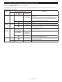
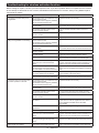
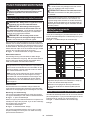
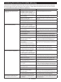
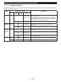
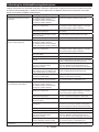
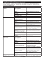
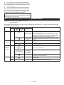
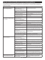
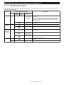
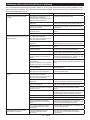
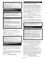
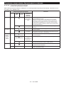
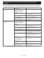
Description of the wireless activation lamp status
► Fig.39: 1. Wireless activation button 2. Wireless
activation lamp
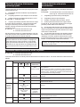
The wireless activation lamp shows the status of the wireless activation function. Refer to the below table for the
meaning of the lamp status.
Status Wireless activation lamp Description
Color
On
Blinking
Duration
(approximate)
Standby Blue Cleaner: con-
tinuing
Tool: 2 hours
Waiting for the tool registration or the wireless activation function
is available.
The lamp on the cleaner blinks when the stand-by switch is set in
AUTO. The lamp on the tool blinks when the wireless activation
button is pushed. The lamp on the tool will automatically turn o
when no operation is performed for 2 hours.
When the tool is
running.
The wireless activation of the cleaner is available and the tool is
running.
Tool
registration
Green 20 seconds Ready for the tool registration. Searching the tool to be registered.
2 seconds The tool registration has been nished. The wireless activation
lamp will start blinking in blue.
Cancelling/
erasing
tool
registration
Red
(slow: 2 times/sec.)
20 seconds Ready for the cancellation of the tool registration. Searching the
tool to be cancelled.
(fast: 5 times/sec.)
When the
wireless acti-
vation button is
pressed down.
Ready to erase all tool registrations.
2 seconds The tool registration has been cancelled/erased. The wireless
activation lamp will start blinking in blue.
Others Red 3 seconds The power is supplied to the wireless unit and the wireless activa-
tion function is starting up.
O - - The stand-by switch is not set to "AUTO".
Sidan laddas...
Sidan laddas...
Sidan laddas...
Sidan laddas...
Sidan laddas...
Sidan laddas...
Sidan laddas...
Sidan laddas...
Sidan laddas...
Sidan laddas...
Sidan laddas...
Sidan laddas...
Sidan laddas...
Sidan laddas...
Sidan laddas...
Sidan laddas...
Sidan laddas...
Sidan laddas...
Sidan laddas...
Sidan laddas...
Sidan laddas...
Sidan laddas...
Sidan laddas...
Sidan laddas...
Sidan laddas...
Sidan laddas...
Sidan laddas...
Sidan laddas...
Sidan laddas...
Sidan laddas...
Sidan laddas...
Sidan laddas...
Sidan laddas...
Sidan laddas...
Sidan laddas...
Sidan laddas...
Sidan laddas...
Sidan laddas...
Sidan laddas...
Sidan laddas...
Sidan laddas...
Sidan laddas...
Sidan laddas...
Sidan laddas...
Sidan laddas...
Sidan laddas...
Sidan laddas...
Sidan laddas...
Sidan laddas...
Sidan laddas...
Sidan laddas...
Sidan laddas...
Sidan laddas...
Sidan laddas...
Sidan laddas...
Sidan laddas...
Sidan laddas...
Sidan laddas...
Sidan laddas...
Sidan laddas...
Sidan laddas...
Sidan laddas...
Sidan laddas...
Sidan laddas...
Sidan laddas...
Sidan laddas...
Sidan laddas...
Sidan laddas...
Sidan laddas...
Sidan laddas...
Sidan laddas...
Sidan laddas...
Sidan laddas...
Sidan laddas...
Sidan laddas...
Sidan laddas...
Sidan laddas...
Sidan laddas...
Sidan laddas...
Sidan laddas...
Sidan laddas...
Sidan laddas...
Sidan laddas...
Sidan laddas...
Sidan laddas...
Sidan laddas...
Sidan laddas...
Sidan laddas...
Sidan laddas...
Sidan laddas...
Sidan laddas...
Sidan laddas...
Sidan laddas...
Sidan laddas...
Sidan laddas...
Sidan laddas...
Sidan laddas...
Sidan laddas...
Sidan laddas...
Sidan laddas...
Sidan laddas...
Sidan laddas...
Sidan laddas...
Sidan laddas...
Sidan laddas...
Sidan laddas...
Sidan laddas...
Sidan laddas...
Sidan laddas...
Sidan laddas...
Sidan laddas...
Sidan laddas...
Sidan laddas...
Sidan laddas...
Sidan laddas...
Sidan laddas...
-
 1
1
-
 2
2
-
 3
3
-
 4
4
-
 5
5
-
 6
6
-
 7
7
-
 8
8
-
 9
9
-
 10
10
-
 11
11
-
 12
12
-
 13
13
-
 14
14
-
 15
15
-
 16
16
-
 17
17
-
 18
18
-
 19
19
-
 20
20
-
 21
21
-
 22
22
-
 23
23
-
 24
24
-
 25
25
-
 26
26
-
 27
27
-
 28
28
-
 29
29
-
 30
30
-
 31
31
-
 32
32
-
 33
33
-
 34
34
-
 35
35
-
 36
36
-
 37
37
-
 38
38
-
 39
39
-
 40
40
-
 41
41
-
 42
42
-
 43
43
-
 44
44
-
 45
45
-
 46
46
-
 47
47
-
 48
48
-
 49
49
-
 50
50
-
 51
51
-
 52
52
-
 53
53
-
 54
54
-
 55
55
-
 56
56
-
 57
57
-
 58
58
-
 59
59
-
 60
60
-
 61
61
-
 62
62
-
 63
63
-
 64
64
-
 65
65
-
 66
66
-
 67
67
-
 68
68
-
 69
69
-
 70
70
-
 71
71
-
 72
72
-
 73
73
-
 74
74
-
 75
75
-
 76
76
-
 77
77
-
 78
78
-
 79
79
-
 80
80
-
 81
81
-
 82
82
-
 83
83
-
 84
84
-
 85
85
-
 86
86
-
 87
87
-
 88
88
-
 89
89
-
 90
90
-
 91
91
-
 92
92
-
 93
93
-
 94
94
-
 95
95
-
 96
96
-
 97
97
-
 98
98
-
 99
99
-
 100
100
-
 101
101
-
 102
102
-
 103
103
-
 104
104
-
 105
105
-
 106
106
-
 107
107
-
 108
108
-
 109
109
-
 110
110
-
 111
111
-
 112
112
-
 113
113
-
 114
114
-
 115
115
-
 116
116
-
 117
117
-
 118
118
-
 119
119
-
 120
120
-
 121
121
-
 122
122
-
 123
123
-
 124
124
-
 125
125
-
 126
126
-
 127
127
-
 128
128
-
 129
129
-
 130
130
-
 131
131
-
 132
132
-
 133
133
-
 134
134
-
 135
135
-
 136
136


på andra språk
- eesti: Makita VC002GL Kasutusjuhend
- dansk: Makita VC002GL Brugermanual
Relaterade papper
-
Makita VC009G Användarmanual
-
Makita HR007G Cordless Combination Hammer Användarmanual
-
-
Makita DKP181 Användarmanual
-
Makita VC008G Användarmanual
-
Makita CL001G Användarmanual
-
-
-
-
Makita PV001G Användarmanual