
PV001G
EN Cordless Polisher INSTRUCTION MANUAL 6
SV Batteridriven
poleringsmaskin BRUKSANVISNING 14
NO Batteridrevet
poleringsmaskin BRUKSANVISNING 22
FI Langaton kiillotin KÄYTTÖOHJE 30
DA Trådløs polérmaskine BRUGSANVISNING 38
LV Bezvada pulētājs LIETOŠANAS INSTRUKCIJA 46
LT Belaidis poliruoklis NAUDOJIMO INSTRUKCIJA 54
ET Juhtmevaba poleerija KASUTUSJUHEND 62
RU Аккумуляторная
полировальная машина РУКОВОДСТВО ПО
ЭКСПЛУАТАЦИИ 70

2
1
3
1
2
Fig.1
1
2
Fig.2
A
B
1
1
Fig.3
1
2
3
Fig.4
1
2
3
Fig.5
1
Fig.6

3
1
2
Fig.7
1
2
3
45
Fig.8
1
1
2
Fig.9
1
13
3
2
4
Fig.10
1
2
Fig.11

4
1
2
Fig.12
4
1
2
3
Fig.13
1
3
2
Fig.14
1
2
3
Fig.15
4
1
2
3
Fig.16
1
3
2
4
Fig.17

5
2
1
3
Fig.18
Fig.19
Fig.20
Fig.21
Fig.22
1
1
Fig.23

6ENGLISH
ENGLISH (Original instructions)
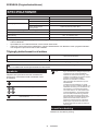
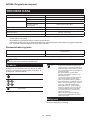
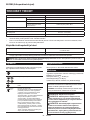
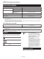
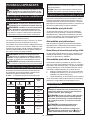
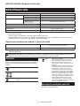
SPECIFICATIONS
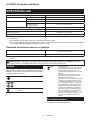
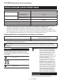
Model: PV001G
Maximum capacities Wool pad 180 mm
Wool bonnet 180 mm
Spindle thread European countries M14
Countries other than Europe
(country specic)
15.88 mm (5/8″) / M16 / M14
Rated speed (n) / No load speed (n0)2,200 min-1
Overall length (with battery cartridge BL4040) 531 mm
Rated voltage D.C. 36 V - 40 V max
Net weight 3.0 - 4.4 kg
• Due to our continuing program of research and development, the specications herein are subject to change
without notice.
• Specications and battery cartridge may dier from country to country.
• The weight may dier depending on the attachment(s), including the battery cartridge. The lightest and heavi-
est combinations, according to EPTA-Procedure 01/2014, are shown in the table.
Applicable battery cartridge and charger
Battery cartridge BL4020 / BL4025* / BL4040* / BL4050F* / BL4080F
* : Recommended battery
Charger DC40RA / DC40RB / DC40RC
• Some of the battery cartridges and chargers listed above may not be available depending on your region of
residence.
WARNING: Only use the battery cartridges and chargers listed above. Use of any other battery cartridges
and chargers may cause injury and/or re.
Symbols
The followings show the symbols which may be used
for the equipment. Be sure that you understand their
meaning before use.
Read instruction manual.
Wear safety glasses.
Maintain a rm grip with both hands on the
power tool.
Ni-MH
Li-ion
Only for EU countries
Due to the presence of hazardous com-
ponents in the equipment, waste electrical
and electronic equipment, accumulators
and batteries may have a negative impact
on the environment and human health.
Do not dispose of electrical and electronic
appliances or batteries with household
waste!
In accordance with the European Directive
on waste electrical and electronic equip-
ment and on accumulators and batteries
and waste accumulators and batteries,
as well as their adaptation to national law,
waste electrical equipment, batteries and
accumulators should be stored separately
and delivered to a separate collection point
for municipal waste, operating in accor-
dance with the regulations on environmen-
tal protection.
This is indicated by the symbol of the
crossed-out wheeled bin placed on the
equipment.
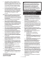
Intended use
The tool is intended for polishing.

7ENGLISH
Noise
The typical A-weighted noise level determined accord-
ing to EN62841-2-3:
Sound pressure level (LpA) : 80 dB(A)
Uncertainty (K) : 3 dB(A)
The noise level under working may exceed 80 dB (A).
NOTE: The declared noise emission value(s) has
been measured in accordance with a standard test
method and may be used for comparing one tool with
another.
NOTE: The declared noise emission value(s)
may also be used in a preliminary assessment of
exposure.
WARNING: Wear ear protection.
WARNING: The noise emission during actual
use of the power tool can dier from the declared
value(s) depending on the ways in which the
tool is used especially what kind of workpiece is
processed.
WARNING: Be sure to identify safety mea-
sures to protect the operator that are based on an
estimation of exposure in the actual conditions of
use (taking account of all parts of the operating
cycle such as the times when the tool is switched
o and when it is running idle in addition to the
trigger time).
Vibration
The vibration total value (tri-axial vector sum) deter-
mined according to EN62841-2-3:
Work mode: polishing
Vibration emission (ah, P) : 2.5 m/s2 or less
Uncertainty (K) : 1.5 m/s2
NOTE: The declared vibration total value(s) has been
measured in accordance with a standard test method
and may be used for comparing one tool with another.
NOTE: The declared vibration total value(s) may also
be used in a preliminary assessment of exposure.
WARNING: The vibration emission during
actual use of the power tool can dier from the
declared value(s) depending on the ways in which
the tool is used especially what kind of workpiece
is processed.
WARNING: Be sure to identify safety mea-
sures to protect the operator that are based on an
estimation of exposure in the actual conditions of
use (taking account of all parts of the operating
cycle such as the times when the tool is switched
o and when it is running idle in addition to the
trigger time).
EC Declaration of Conformity
For European countries only
The EC declaration of conformity is included as Annex A
to this instruction manual.
SAFETY WARNINGS
General power tool safety warnings
WARNING: Read all safety warnings, instruc-
tions, illustrations and specications provided
with this power tool. Failure to follow all instructions
listed below may result in electric shock, re and/or
serious injury.
Save all warnings and instruc-
tions for future reference.
The term "power tool" in the warnings refers to your
mains-operated (corded) power tool or battery-operated
(cordless) power tool.
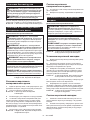
Cordless polisher safety warnings
Safety Warnings for Polishing Operations:
1.
This power tool is intended to function as a pol-
isher. Read all safety warnings, instructions, illus-
trations and specications provided with this power
tool. Failure to follow all instructions listed below may
result in electric shock, re and/or serious injury.
2. Operations such as grinding, sanding, wire
brushing, hole cutting or cutting-o are not to
be performed with this power tool. Operations
for which the power tool was not designed may
create a hazard and cause personal injury.
3.
Do not convert this power tool to operate in a way
which is not specically designed and specied by
the tool manufacturer. Such a conversion may result
in a loss of control and cause serious personal injury.
4.
Do not use accessories which are not specically
designed and specied by the tool manufacturer.
Just because the accessory can be attached to your
power tool, it does not assure safe operation.
5. The rated speed of the accessory must be at
least equal to the maximum speed marked on
the power tool. Accessories running faster than
their rated speed can break and y apart.
6. The outside diameter and the thickness of your
accessory must be within the capacity rating
of your power tool. Incorrectly sized accessories
cannot be adequately guarded or controlled.
7.
The dimensions of the accessory mounting must
t the dimensions of the mounting hardware of the
power tool. Accessories that do not match the mount-
ing hardware of the power tool will run out of balance,
vibrate excessively and may cause loss of control.
8. Do not use a damaged accessory. Before each
use inspect the accessory such as abrasive
wheels for chips and cracks, backing pad for
cracks, tear or excess wear, wire brush for
loose or cracked wires. If power tool or acces-
sory is dropped, inspect for damage or install
an undamaged accessory. After inspecting and
installing an accessory, position yourself and
bystanders away from the plane of the rotating
accessory and run the power tool at maximum
no-load speed for one minute. Damaged acces-
sories will normally break apart during this test
time.

8ENGLISH
9. Wear personal protective equipment.
Depending on application, use face shield,
safety goggles or safety glasses. As appro-
priate, wear dust mask, hearing protectors,
gloves and workshop apron capable of stop-
ping small abrasive or workpiece fragments.
The eye protection must be capable of stopping
ying debris generated by various applications.
The dust mask or respirator must be capable
of ltrating particles generated by the particular
application. Prolonged exposure to high intensity
noise may cause hearing loss.
10. Keep bystanders a safe distance away from
work area. Anyone entering the work area
must wear personal protective equipment.
Fragments of workpiece or of a broken accessory
may y away and cause injury beyond immediate
area of operation.
11. Never lay the power tool down until the acces-
sory has come to a complete stop. The spinning
accessory may grab the surface and pull the
power tool out of your control.
12. Do not run the power tool while carrying it at
your side. Accidental contact with the spinning
accessory could snag your clothing, pulling the
accessory into your body.
13. Regularly clean the power tool’s air vents. The
motor’s fan will draw the dust inside the housing
and excessive accumulation of powdered metal
may cause electrical hazards.
14. Do not operate the power tool near ammable
materials. Sparks could ignite these materials.
15. Do not use accessories that require liquid
coolants. Using water or other liquid coolants
may result in electrocution or shock.
16.
Do not allow any loose portion of the polishing
bonnet or its attachment strings to spin freely.
Tuck away or trim any loose attachment strings.
Loose and spinning attachment strings can entangle
your ngers or snag on the workpiece.
Kickback and Related Warnings
Kickback is a sudden reaction to a pinched or snagged
rotating wheel, backing pad, brush or any other acces-
sory. Pinching or snagging causes rapid stalling of the
rotating accessory which in turn causes the uncon-
trolled power tool to be forced in the direction opposite
of the accessory’s rotation at the point of the binding.
For example, if an abrasive wheel is snagged or
pinched by the workpiece, the edge of the wheel that is
entering into the pinch point can dig into the surface of
the material causing the wheel to climb out or kick out.
The wheel may either jump toward or away from the
operator, depending on direction of the wheel’s move-
ment at the point of pinching. Abrasive wheels may also
break under these conditions.
Kickback is the result of power tool misuse and/or
incorrect operating procedures or conditions and can be
avoided by taking proper precautions as given below.
1. Maintain a rm grip with both hands on the
power tool and position your body and arms
to allow you to resist kickback forces. Always
use auxiliary handle, if provided, for maxi-
mum control over kickback or torque reaction
during start-up. The operator can control torque
reactions or kickback forces, if proper precautions
are taken.
2. Never place your hand near the rotating acces-
sory. Accessory may kickback over your hand.
3. Do not position your body in the area where
power tool will move if kickback occurs.
Kickback will propel the tool in direction opposite
to the wheel’s movement at the point of snagging.
4. Use special care when working corners, sharp
edges, etc. Avoid bouncing and snagging the
accessory. Corners, sharp edges or bouncing
have a tendency to snag the rotating accessory
and cause loss of control or kickback.
5. Do not attach a saw chain woodcarving blade,
segmented diamond wheel with a peripheral
gap greater than 10 mm or toothed saw blade.
Such blades create frequent kickback and loss of
control.
Additional Safety Warnings:
1. Be careful not to damage the spindle, the
ange (especially the installing surface) or the
lock nut. Damage to these parts could result in
wheel breakage.
2. Make sure the wheel is not contacting the
workpiece before the switch is turned on.
3. Before using the tool on an actual workpiece,
let it run for a while. Watch for vibration or
wobbling that could indicate poor installation
or a poorly balanced wheel.
4. Use the specied surface of the wheel to per-
form polishing.
5. Do not leave the tool running. Operate the tool
only when hand-held.
6. Do not touch the workpiece immediately after
operation; it may be extremely hot and could
burn your skin.
7. Do not touch accessories immediately after
operation; it may be extremely hot and could
burn your skin.
8. Observe the instructions of the manufacturer
for correct mounting and use of wheels.
Handle and store wheels with care.
9. For tools intended to be tted with threaded
hole wheel, ensure that the thread in the wheel
is long enough to accept the spindle length.
10. Check that the workpiece is properly
supported.
11. Pay attention that the wheel continues to
rotate after the tool is switched o.
12. Do not use the tool on any materials contain-
ing asbestos.
13. Do not use cloth work gloves during operation.
Fibers from cloth gloves may enter the tool, which
causes tool breakage.
SAVE THESE INSTRUCTIONS.
WARNING: DO NOT let comfort or familiarity
with product (gained from repeated use) replace
strict adherence to safety rules for the subject
product. MISUSE or failure to follow the safety
rules stated in this instruction manual may cause
serious personal injury.

9ENGLISH
Important safety instructions for
battery cartridge
1. Before using battery cartridge, read all instruc-
tions and cautionary markings on (1) battery
charger, (2) battery, and (3) product using
battery.
2. Do not disassemble or tamper with the battery
cartridge. It may result in a re, excessive heat,
or explosion.
3. If operating time has become excessively
shorter, stop operating immediately. It may
result in a risk of overheating, possible burns
and even an explosion.
4. If electrolyte gets into your eyes, rinse them
out with clear water and seek medical atten-
tion right away. It may result in loss of your
eyesight.
5. Do not short the battery cartridge:
(1) Do not touch the terminals with any con-
ductive material.
(2) Avoid storing battery cartridge in a con-
tainer with other metal objects such as
nails, coins, etc.
(3) Do not expose battery cartridge to water
or rain.
A battery short can cause a large current
ow, overheating, possible burns and even a
breakdown.
6. Do not store and use the tool and battery car-
tridge in locations where the temperature may
reach or exceed 50 °C (122 °F).
7. Do not incinerate the battery cartridge even if
it is severely damaged or is completely worn
out. The battery cartridge can explode in a re.
8. Do not nail, cut, crush, throw, drop the battery
cartridge, or hit against a hard object to the
battery cartridge. Such conduct may result in a
re, excessive heat, or explosion.
9. Do not use a damaged battery.
10. The contained lithium-ion batteries are subject
to the Dangerous Goods Legislation require-
ments.
For commercial transports e.g. by third parties,
forwarding agents, special requirement on pack-
aging and labeling must be observed.
For preparation of the item being shipped, consult-
ing an expert for hazardous material is required.
Please also observe possibly more detailed
national regulations.
Tape or mask o open contacts and pack up the
battery in such a manner that it cannot move
around in the packaging.
11. When disposing the battery cartridge, remove
it from the tool and dispose of it in a safe
place. Follow your local regulations relating to
disposal of battery.
12. Use the batteries only with the products
specied by Makita. Installing the batteries to
non-compliant products may result in a re, exces-
sive heat, explosion, or leak of electrolyte.
13. If the tool is not used for a long period of time,
the battery must be removed from the tool.
14. During and after use, the battery cartridge may
take on heat which can cause burns or low
temperature burns. Pay attention to the han-
dling of hot battery cartridges.
15. Do not touch the terminal of the tool imme-
diately after use as it may get hot enough to
cause burns.
16. Do not allow chips, dust, or soil stuck into the
terminals, holes, and grooves of the battery
cartridge. It may cause heating, catching re,
burst and malfunction of the tool or battery car-
tridge, resulting in burns or personal injury.
17. Unless the tool supports the use near
high-voltage electrical power lines, do not use
the battery cartridge near a high-voltage elec-
trical power lines. It may result in a malfunction
or breakdown of the tool or battery cartridge.
18. Keep the battery away from children.
SAVE THESE INSTRUCTIONS.
CAUTION: Only use genuine Makita batteries.
Use of non-genuine Makita batteries, or batteries that
have been altered, may result in the battery bursting
causing res, personal injury and damage. It will
also void the Makita warranty for the Makita tool and
charger.
Tips for maintaining maximum
battery life
1. Charge the battery cartridge before completely
discharged. Always stop tool operation and
charge the battery cartridge when you notice
less tool power.
2. Never recharge a fully charged battery car-
tridge. Overcharging shortens the battery
service life.
3. Charge the battery cartridge with room tem-
perature at 10 °C - 40 °C (50 °F - 104 °F). Let
a hot battery cartridge cool down before
charging it.
4. When not using the battery cartridge, remove
it from the tool or the charger.
5. Charge the battery cartridge if you do not use
it for a long period (more than six months).

10 ENGLISH
FUNCTIONAL DESCRIPTION
CAUTION: Always be sure that the tool is
switched o and the battery cartridge is removed
before adjusting or checking function on the tool.
Installing or removing battery cartridge
CAUTION: Always switch o the tool before
installing or removing of the battery cartridge.
CAUTION: Hold the tool and the battery car-
tridge rmly when installing or removing battery
cartridge. Failure to hold the tool and the battery
cartridge rmly may cause them to slip o your hands
and result in damage to the tool and battery cartridge
and a personal injury.
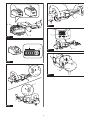
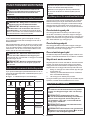
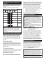
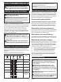
► Fig.1: 1. Red indicator 2. Button 3. Battery cartridge
To remove the battery cartridge, slide it from the tool
while sliding the button on the front of the cartridge.
To install the battery cartridge, align the tongue on the
battery cartridge with the groove in the housing and slip
it into place. Insert it all the way until it locks in place
with a little click. If you can see the red indicator as
shown in the gure, it is not locked completely.
CAUTION: Always install the battery cartridge
fully until the red indicator cannot be seen. If not,
it may accidentally fall out of the tool, causing injury to
you or someone around you.
CAUTION: Do not install the battery cartridge
forcibly. If the cartridge does not slide in easily, it is
not being inserted correctly.
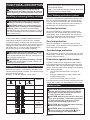
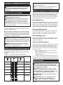
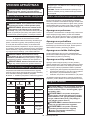
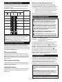
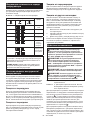
Indicating the remaining battery capacity
Press the check button on the battery cartridge to indi-
cate the remaining battery capacity. The indicator lamps
light up for a few seconds.
► Fig.2: 1. Indicator lamps 2. Check button
Indicator lamps Remaining
capacity
Lighted O Blinking
75% to 100%
50% to 75%
25% to 50%
0% to 25%
Charge the
battery.
The battery
may have
malfunctioned.
NOTE: Depending on the conditions of use and the
ambient temperature, the indication may dier slightly
from the actual capacity.
NOTE: The rst (far left) indicator lamp will blink when
the battery protection system works.
Tool / battery protection system
The tool is equipped with a tool/battery protection sys-
tem. This system automatically cuts o power to the
motor to extend tool and battery life. The tool will auto-
matically stop during operation if the tool or battery is
placed under one of the following conditions:
Overload protection
When the tool/battery is operated in a manner that
causes it to draw an abnormally high current, the tool
automatically stops. In this situation, turn the tool o
and stop the application that caused the tool to become
overloaded. Then turn the tool on to restart.
Overheat protection
When the tool/battery is overheated, the tool stops
automatically. In this situation, let the tool/battery cool
before turning the tool on again.
Overdischarge protection
When the battery capacity is not enough, the tool stops
automatically. In this case, remove the battery from the
tool and charge the battery.
Protections against other causes
Protection system is also designed for other causes
that could damage the tool and allows the tool to stop
automatically. Take all the following steps to clear the
causes, when the tool has been brought to a temporary
halt or stop in operation.
1. Turn the tool o, and then turn it on again to
restart.
2. Charge the battery(ies) or replace it/them with
recharged battery(ies).
3. Let the tool and battery(ies) cool down.
If no improvement can be found by restoring protection
system, then contact your local Makita Service Center.
Switch action
CAUTION: Before installing the battery car-
tridge into the tool, always check to see that the
switch trigger actuates properly and returns to
the "OFF" position when released.
CAUTION: Switch can be locked in "ON" posi-
tion for ease of operator comfort during extended
use. Apply caution when locking tool in "ON"
position and maintain rm grasp on tool.
CAUTION: Do not install the battery cartridge
with the lock button engaged.
CAUTION: When not operating the tool,
depress the trigger-lock button from side to
lock the switch trigger in the OFF position.

11 ENGLISH
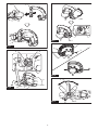
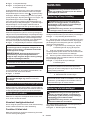
► Fig.3: 1. Trigger-lock button
► Fig.4: 1. Switch trigger 2. Lock button 3. Trigger-
lock button
To prevent the switch trigger from accidentally pulled, the
trigger-lock button is provided. To start the tool, depress
the trigger-lock button from A ( ) side and pull the switch
trigger. Tool speed is increased by increasing pressure on
the switch trigger. Release the switch trigger to stop. After
use, depress the trigger-lock button from B ( ) side.
For continuous operation, depress the lock button while
pulling the switch trigger, and then release the switch
trigger. To stop the tool, pull the switch trigger fully, then
release it.
Speed adjusting dial
The rotating speed can be changed by using the speed
adjusting dial on top of the switch handle. Turn the
speed adjusting dial to align the pointers with your
desired rotating speed indicated on the speed scale.
The rotating speed can be adjusted from 600 (RPM) to
2,200 (RPM), and a target speed can be obtained when
the switch trigger is fully squeezed.
► Fig.5:
1. Speed adjusting dial 2. Pointer 3. Speed scale
NOTICE: If the tool is operated continuously
at low speeds for a long time, the motor will get
overloaded, resulting in tool malfunction.
NOTICE: The speed adjusting dial turns between
600 and 2,200 on the speed scale. Avoid turning
the dial back and forwards further as it may cause
damage to the tool.
NOTE: Be sure to read numbers on the scale as an
indicator since the actual speed may uctuate slightly.
Shaft lock
Press the shaft lock to prevent spindle rotation when
installing and removing accessories.
► Fig.6: 1. Shaft lock
NOTICE: Never actuate the shaft lock while the
spindle is moving. The tool may be damaged.
Accidental restart preventive function
If you install the battery cartridge while pulling the
switch trigger or locking the switch trigger, the tool does
not start. To start the tool, release the switch trigger, and
then pull the switch trigger.
Electronic function
The tool is equipped with the following electronic func-
tions for easy operation.
Constant speed control
Possible to get ne nish, because the rotating speed is
kept constant even under the loaded condition.
Soft start feature
The soft-start function minimizes start-up shock, and
makes the tool start smoothly.
ASSEMBLY
CAUTION: Always be sure that the tool is
switched o and the battery cartridge is removed
before carrying out any work on the tool.
Installing loop handle
CAUTION: Be sure to hold the tool rmly with
both hands, positioning one hand on the switch
handle and the other on the loop handle, side grip
or tool head.
CAUTION: Make sure that the loop handle is
installed securely before operation.
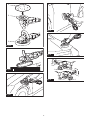
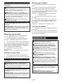
1. Place the loop handle over the tool head by pass-
ing the tool head through the loop of the handle.
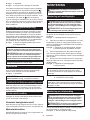
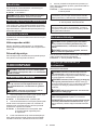
► Fig.7: 1. Loop handle 2. Tool head
2. Attach the straight end of the loop handle over the
mounting hole on side of the tool head, tting the guide
ridges on the handle end well into the guide grooves
around the mounting hole.
► Fig.8: 1. Straight end of loop handle 2. Spindle
3. Mounting hole 4. Guide ridge 5. Guide
groove
3. Hold the loop handle and pull the loop end over
the mounting hole on the other side of the tool head,
rening angles to engage the handle position.
4. Install and tighten the hex bolts into the mounting
holes on both sides of the tool head to secure the loop
handle in place.
► Fig.9: 1. Loop end of loop handle 2. Mounting hole
NOTE: The loop handle has an asymmetric shape
that can be applied for left or right hand, making
it more comfortable for you to grip and easy for
polishing.
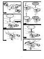
► Fig.10: 1. Loop handle 2. Tool head 3. Hex bolt
4. Hex wrench
NOTE: The loop handle can be laid down back and
forwards according to your preferred position. Loosen
the hex bolts, move the handle to your desired angle
and then refasten the bolts to lock the angle.
► Fig.11: 1. Loop handle 2. Hex bolt
Installing side grip
CAUTION: Be sure to hold the tool rmly with
both hands, positioning one hand on the switch
handle and the other on the loop handle, side grip
or tool head.
CAUTION: Make sure that the side grip is
installed securely before operation.
Screw the side grip tightly into the mounting hole on
either side of the tool head.
► Fig.12: 1. Mounting hole 2. Side grip

12 ENGLISH
Installing and removing wool pad
Optional accessory
CAUTION: Make sure that the backing pad is
secured properly. Loose attachment will run out of
balance and cause an excessive vibration which may
cause loss of control.
CAUTION: Make sure that the wool pad and
backing pad are aligned and securely attached.
Otherwise the wool pad will cause an excessive vibra-
tion which may cause loss of control or the wool pad
may be thrown out from the tool.
CAUTION: Only use the hook-and-loop sys-
tem wool pads for polishing.
NOTICE: Never actuate the shaft lock when the
spindle is moving. The tool may be damaged.
NOTICE: Regularly clean accessories and spin-
dle to remove dust and debris. Wipe the compo-
nents clean with a cloth dampened in soapy water if
necessary.
► Fig.13:
1. Wool pad 2. Sleeve 18 3. Backing pad 4. Spindle
Installing wool pad
1. Press in the shaft lock to prevent spindle rotation,
and thread the backing pad into the spindle.
2. Hand tighten the backing pad securely.
► Fig.14: 1. Shaft lock 2. Backing pad 3. Spindle
3. Insert the sleeve 18 into the center hole of the
backing pad.
4. Install the wool pad over the backing pad, passing
the sleeve 18 through the center hole of the wool pad.
Use the sleeve 18 as a positioning guide to align the
wool pad accurately along the backing pad.
5.
Pull the sleeve 18 out of the center hole of the backing pad.
► Fig.15: 1. Sleeve 18 2. Backing pad 3. Wool pad
Removing wool pad
1. Gently peel the wool pad o the backing pad.
2. Unscrew the backing pad while pressing in the
shaft lock.
Installing and removing wool bonnet
Optional accessory
CAUTION: Make sure that the rubber pad is
secured properly. Loose attachment will run out of
balance and cause an excessive vibration which may
cause loss of control.
NOTICE: Never actuate the shaft lock when the
spindle is moving. The tool may be damaged.
NOTICE: Regularly clean accessories and spin-
dle to remove dust and debris. Wipe the compo-
nents clean with a cloth dampened in soapy water if
necessary.
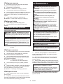
► Fig.16: 1. Wool bonnet 2. Lock nut 3. Rubber pad
4. Spindle
Installing wool bonnet
1. Press in the shaft lock to prevent spindle rotation.
2. Place the rubber pad over the spindle, passing
the spindle thread through the center hole of the rubber
pad.
3. Install the lock nut onto the spindle, and then
tighten it clockwise using the lock nut wrench to secure
the rubber pad rmly in place.
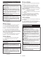
► Fig.17: 1. Shaft lock 2. Rubber pad 3. Lock nut
4. Lock nut wrench
4. Lay the wool bonnet down over the rubber pad
and cover up completely.
5. Turn the tool upside down. Pull the strings tight
and tie a bow knot. Then tuck the knot and any loose
strings between the wool bonnet and the rubber pad.
► Fig.18: 1. Wool bonnet 2. Rubber pad 3. Strings
Removing wool bonnet
1. Untie the bow knot and gently remove the wool
bonnet from the rubber pad.
2. Loosen the lock nut counterclockwise with the lock
nut wrench while pressing in the shaft lock. Pull the lock
nut and rubber pad o the spindle.
OPERATION
CAUTION: Only use Makita genuine pads for
polishing (optional accessories).
CAUTION: Be sure to hold the tool rmly with
both hands, positioning one hand on the switch
handle and the other on the loop handle, side grip
or tool head.
CAUTION: Make sure that the loop handle or
side grip is installed securely before operation.
CAUTION: Make sure the work material is
secured and stable. Falling object may cause
personal injury.
CAUTION: Do not run the tool at high load
over an extended time period. It may result in tool
malfunction which causes electric shock, re and/or
serious injury.
CAUTION: Be careful not to touch the rotating
part.
NOTICE: Never force the tool. Excessive pressure
may lead to decreased polishing eciency, damaged
pad, or shorten tool life.
NOTICE: Continuous operation at high speed
may damage work surface.

13 ENGLISH
Polishing basics
CAUTION: Always wear safety glasses or a
face shield during operation.
NOTICE: It is recommended that you have a trial
run over an inconspicuous spot to nd an appro-
priate workload.
► Fig.19
1. Make sure that the workpiece is properly sup-
ported and both hands are free to control the tool.
2. Hold the tool rmly with one hand on the switch
handle and the other hand on the loop handle, side grip
or tool head.
3. Turn the tool on, letting the polishing wheel reach
full speed. Then carefully enter into operation moving
the tool back and forth with steady pressure over the
workpiece surface.
NOTE: Keep the wool pad/bonnet at an angle of
about 15 degrees to the workpiece surface.
NOTE: Apply an even amount of gentle pressure over
the polishing wheel. Excessive pressure will result in
poor performance and premature wear to wool pad/
bonnet.
4. Having nished, switch the tool o and wait until
the wheel has come to a complete stop before putting
the tool down.
Polishing operations
Surface treatment
Use a wool pad for rough nishing, then use a sponge
pad (optional accessory) for ne nishing.
► Fig.20
Applying wax
Apply wax to the sponge pad (optional accessory) or
work surface. Run the tool at low speed to smooth out
wax.
► Fig.21
CAUTION: Do not apply excessive wax or
polishing agent. It will generate more dust and may
cause eye or respiratory diseases.
NOTE: First, perform a test waxing on an inconspic-
uous portion of the work surface. Make sure that the
tool will not scratch the surface, or it may result in
uneven waxing.
Removing wax
Apply with a clean sponge pad (optional accessory).
Run the tool to remove wax.
► Fig.22
MAINTENANCE
CAUTION: Always be sure that the tool is
switched o and the battery cartridge is removed
before attempting to perform inspection or
maintenance.
NOTICE: Never use gasoline, benzine, thinner,
alcohol or the like. Discoloration, deformation or
cracks may result.
To maintain product SAFETY and RELIABILITY,
repairs, any other maintenance or adjustment should
be performed by Makita Authorized or Factory Service
Centers, always using Makita replacement parts.
Cleaning dust covers
► Fig.23: 1. Dust cover
Regularly clean the dust covers on the inhalation vents
for smooth air circulation. Remove the dust covers and
clean the mesh.
OPTIONAL
ACCESSORIES
CAUTION: These accessories or attachments
are recommended for use with your Makita tool
specied in this manual. The use of any other
accessories or attachments might present a risk of
injury to persons. Only use accessory or attachment
for its stated purpose.
If you need any assistance for more details regard-
ing these accessories, ask your local Makita Service
Center.
• Lock nut 48
• Lock nut wrench 28
• Sponge pad (Hook & loop)
• Wool pad 180 (Hook & loop)
• Wool bonnet 180
• Backing pad 165 (Hook & loop)
• Rubber pad 170
• Sleeve 18
• Side grip (auxiliary handle)
• Loop handle
• Makita genuine battery and charger
NOTE: Some items in the list may be included in the
tool package as standard accessories. They may
dier from country to country.

14 SVENSKA
SVENSKA (Originalinstruktioner)
SPECIFIKATIONER
Modell: PV001G
Max. kapacitet Ullhätta 180 mm
Ullhätta 180 mm
Spindelgänga Länder i Europa M14
Länder utanför Europa
(landsspecikt)
15,88 mm (5/8 tum) / M16 / M14
Nominellt varvtal (n)/hastighet utan belastning (n0)2 200 min-1
Total längd (med batterikassett BL4040) 531 mm
Märkspänning 36 V - 40 V likström max
Nettovikt 3,0 - 4,4 kg
• På grund av vårt pågående program för forskning och utveckling kan dessa specikationer ändras utan föregå-
ende meddelande.
• Specikationer och batterikassett kan variera mellan olika länder.
• Vikten kan variera beroende på tillbehören, inklusive batterikassett. Den lättaste och den tyngsta kombinatio-
nen enligt EPTA-procedur 01/2014 visas i tabellen.
Tillgänglig batterikassett och laddare
Batterikassett BL4020 / BL4025* / BL4040* / BL4050F* / BL4080F
* : Rekommenderat batteri
Laddare DC40RA / DC40RB / DC40RC
• Vissa av batterikassetterna och laddarna på listan ovan kanske inte nns tillgängliga i din region.
VARNING: Använd endast batterikassetter och laddare från listan ovan. Användning av andra batterikas-
setter och laddare kan orsaka personskada och/eller brand.
Symboler
Följande visar symbolerna som kan användas för
utrustningen. Se till att du förstår innebörden innan
användning.
Läs igenom bruksanvisningen.
Använd skyddsglasögon.
Håll ett stadigt grepp i elverktyget med
båda händerna.
Ni-MH
Li-ion
Gäller endast inom EU
P.g.a. förekomsten av farliga komponenter
i utrustningen kan avfall innehållande
elektrisk och elektronisk utrustning, acku-
mulatorer och batterier ha negativ inverkan
på miljön och människors hälsa.
Kassera inte elektriska och elektro-
niska apparater eller batterier ihop med
hushållsavfall!
I enlighet med EU-direktiven om avfall
som utgörs av eller innehåller elektrisk och
elektronisk utrustning och om batterier och
ackumulatorer och förbrukade batterier
och ackumulatorer, och dess införlivande
i nationell lagstiftning, bör förbrukad elek-
trisk och elektronisk utrustning, batterier
och ackumulatorer förvaras separat och
transporteras till en särskild uppsamlings-
plats för kommunalt avfall, som drivs i
enlighet med regelverket för miljöskydd.
Detta anges av symbolen med den över-
kryssade soptunnan på hjul som sitter på
utrustningen.
Avsedd användning
Maskinen är avsedd för polering.

15 SVENSKA
Buller
Den normala bullernivån för A-belastning är bestämd
enligt EN62841-2-3:
Ljudtrycksnivå (LpA) : 80 dB (A)
Mättolerans (K): 3 dB (A)
Bullernivån vid arbete kan överstiga 80 dB (A).
OBS: Det deklarerade bullervärdet har uppmätts i
enlighet med standardtestmetoden och kan användas
för jämförandet av en maskin med en annan.
OBS: Det deklarerade bulleremissionsvärdet kan
också användas i en preliminär bedömning av expo-
nering för vibration.
VARNING: Använd hörselskydd.
VARNING:
Bulleremissionen under faktisk
användning av maskinen kan skilja sig från det dekla-
rerade värdet, beroende på hur maskinen används och
särskilt vilken typ av arbetsstycke som behandlas.
VARNING: Var noga med att identiera säker-
hetsåtgärder för att skydda användaren, vilka är
grundade på en uppskattning av graden av expo-
nering för vibrationer under de faktiska använd-
ningsförhållandena, (ta, förutom avtryckartiden,
med alla delar av användarcykeln i beräkningen,
som till exempel tiden då maskinen är avstängd
och när den går på tomgång).
Vibration
Det totala vibrationsvärdet (treaxlad vektorsumma)
bestämt enligt EN62841-2-3:
Arbetsläge: polering
Vibrationsemission (ah, P): 2,5 m/s2 eller lägre
Mättolerans (K): 1,5 m/s2
OBS: Det deklarerade totala vibrationsvärdet har
uppmätts i enlighet med standardtestmetoden och
kan användas för jämförandet av en maskin med en
annan.
OBS: Det deklarerade totala vibrationsvärdet kan
också användas i en preliminär bedömning av expo-
nering för vibration.
VARNING: Vibrationsemissionen under fak-
tisk användning av maskinen kan skilja sig från
det deklarerade värdet, beroende på hur maski-
nen används och särskilt vilken typ av arbetss-
tycke som behandlas.
VARNING: Var noga med att identiera säker-
hetsåtgärder för att skydda användaren, vilka är
grundade på en uppskattning av graden av expo-
nering för vibrationer under de faktiska använd-
ningsförhållandena, (ta, förutom avtryckartiden,
med alla delar av användarcykeln i beräkningen,
som till exempel tiden då maskinen är avstängd
och när den går på tomgång).
EG-försäkran om överensstämmelse
Gäller endast inom EU
EG-försäkran om överensstämmelse inkluderas som
bilaga A till denna bruksanvisning.
SÄKERHETSVARNINGAR
Allmänna säkerhetsvarningar för
maskiner
VARNING: Läs alla säkerhetsvarningar, anvis-
ningar, illustrationer och specikationer som
medföljer det här maskinen. Underlåtenhet att följa
instruktionerna kan leda till elstötar, brand och/eller
allvarliga personskador.
Spara alla varningar och instruk-
tioner för framtida referens.
Termen ”maskin” som anges i varningarna hänvisar till
din eldrivna maskin (sladdansluten) eller batteridrivna
maskin (sladdlös).
Säkerhetsvarningar för batteridriven
poleringsmaskin
Säkerhetsvarningar för poleringsarbeten:
1. Detta elverktyg är avsett att fungera som en
poleringsmaskin. Läs igenom alla säkerhets-
varningar, instruktioner, illustrationer och
specikationer som medföljer detta elverktyg.
Underlåtenhet att följa instruktionerna kan leda till
elstötar, brand och/eller allvarliga personskador.
2. Arbeten som slipning, stålborstning, hålskär-
ning eller kapning får inte utföras med det här
elverktyget. Om elverktyget används till andra
arbeten än de avsedda kan det orsaka fara och
leda till personskada.
3. Omvandla inte det här elverktyg så att det
fungerar på ett sätt som det inte särskilt är
utformat och specicerat för av verktygstill-
verkaren. En sådan omvandling kan leda till att
du förlorar kontrollen och kan orsaka allvarlig
personskada.
4. Använd inte tillbehör som inte är särskilt utfor-
made och specicerade av verktygstillverka-
ren. Även om ett tillbehör kan fästas på elverkty-
get garanterar inte detta säker drift.
5. Tillbehörets nominella varvtal måste vara
minst lika med det maximala varvtalet som
anges på verktyget. Tillbehör som används över
det nominella varvtalet kan gå sönder och orsaka
skador.
6. Tillbehörets ytterdiameter och tjocklek måste
vara anpassad till elverktygets kapacitets-
klassning. Tillbehör i olämplig storlek kan inte
skyddas eller styras tillräckligt väl.
7. Måtten på tillbehörets fäste måste stämma
överens med måtten på elverktygets mon-
teringsbeslag. Tillbehör som inte passar exakt
på verktygets monteringsbeslag roterar ojämnt,
vibrerar kraftigt och kan leda till att du förlorar
kontrollen.

16 SVENSKA
8. Använd inte ett skadat tillbehör. Kontrollera
tillbehör som sliprondeller efter hack och
sprickor, underlagsplattor efter sprickor,
slitage och stålborstar efter lösa eller brutna
trådar. Om du tappar maskinen eller ett tillbe-
hör ska du kontrollera att det inte har uppstått
några skador, eller så ska tillbehöret bytas ut
mot ett oskadat. Efter kontroll och montering
av tillbehöret ska du och åskådare hålla er
borta från det roterande tillbehöret samtidigt
som du kör maskinen på full fart utan last i
en minut. Skadade tillbehör går normalt sönder
under den här testtiden.
9. Använd personlig skyddsutrustning. Använd
visir, korgglasögon eller skyddsglasögon
beroende på arbetsuppgift. Använd vid behov
dammskydd, hörselskydd, handskar och
skyddsförkläde som stoppar små bitar av
slipmaterial eller fragment från arbetsstycket.
Ögonskyddet måste kunna stoppa ygande
fragment som uppstår vid olika arbetsuppgifter.
Dammskyddet eller andningsskyddet måste kunna
ltrera partiklar som uppstår vid olika arbetsupp-
gifter. Långvarig exponering för kraftigt buller kan
orsaka hörselskador.
10. Håll personer i omgivningen på säkert avstånd
från arbetsområdet. Alla som benner sig
i arbetsområdet måste använda skyddsut-
rustning. Delar av arbetsstycket eller defekta
tillbehör kan yga iväg och orsaka skador utanför
arbetsområdet.
11. Lägg aldrig elverktyget åt sidan förrän det har
stannat helt. Det roterande tillbehöret kan gripa
tag i underlaget och du kan förlora kontrollen över
maskinen.
12. Kör inte verktyget samtidigt som du bär det.
Oavsiktlig kontakt med det roterande tillbehöret
kan leda till att det fastnar i dina kläder och dras in
mot kroppen.
13. Rengör regelbundet verktygets ventilations-
öppningar. Motorns äkt suger in damm i höljet
och överdriven ansamling av pulveriserad metall
kan orsaka elektrisk fara.
14.
Använd inte verktyget i närheten av lättantänd-
liga material. Gnistor kan antända dessa material.
15.
Använd inte tillbehör som kräver ytande kyl-
vätskor. Att använda vatten eller andra ytande
kylvätskor kan orsaka dödsfall eller elektriska stötar.
16.
Låt inte lösa delar av poleringshättan eller dess
fastsättningsband snurra fritt. Stoppa undan
eller klipp av eventuella lösa fastsättningsband.
Lösa eller snurrande fastsättningsband kan fastna i
dina ngrar eller haka fast i arbetsstycket.
Bakåtkast och relaterade varningar
Bakåtkast är en plötslig reaktion på fastnypt roterande
hjul, underlagsplatta, borste eller annat tillbehör. Nyp
och kärvning orsakar stegring av det roterande tillbehö-
ret, och orsakar i sin tur att den okontrollerade maski-
nen tvingas i motsatt riktning vid kärvningspunkten.
Om till exempel en slipskiva fastnar i eller kläms fast av
arbetsstycket kan skivans kapande kant gräva sig in i
materialytan vid klämpunkten, vilket leder till att skivan
klättrar eller kastas tillbaka. Skivan kan antingen hoppa
mot eller från användaren, beroende på skivans rörel-
seriktning vid klämpunkten. Slipskivorna kan även gå
sönder under dessa omständigheter.
Bakåtkast beror på ovarsamhet och/eller felaktiga
arbetsrutiner, och kan undvikas genom att vidta nedan-
stående förebyggande åtgärder.
1. Håll ett stadigt grepp i elverktyget med båda
händerna och placera kroppen och din arm
på ett sätt som gör att du kan stå emot kraften
från bakåtkast. Använd alltid ett extrahandtag,
om sådant nns, för maximal kontroll vid bak-
åtkast eller vridrörelsen vid start. Användaren
kan kontrollera vridrörelsen eller krafterna vid
bakåtkast om rätt försiktighetsåtgärder vidtas.
2. Placera aldrig din hand nära det roterande
tillbehöret. Tillbehöret kan kastas bakåt över din
hand.
3. Ställ dig inte där maskinen kommer att förytta
sig i händelse av bakåtkast. Bakåtkast driver
verktyget i motsatt riktning till kapskivans rörelse
vid kärvningspunkten.
4. Var särskilt försiktig när du arbetar med
hörn, vassa kanter etc. Undvik att studsa och
klämma tillbehöret. Hörn, skarpa kanter eller
studsning har en tendens att klämma det rote-
rande tillbehöret och orsaka förlorad kontroll eller
bakåtkast.
5. Montera inte en sågkedja, ett snidarblad
eller en segmenterad diamantskiva med en
segmenthöjd på över 10 mm eller ett tandat
sågblad. Sådana blad orsakar ofta bakåtkast och
förlorad kontroll.
Ytterligare säkerhetsvarningar:
1. Var försiktig så att inte spindeln, änsen (i
synnerhet monteringsytan) eller låsmuttern
skadas. Skador på någon av dessa delar kan
medföra att rondellen förstörs.
2. Se till att rondellen inte är i kontakt med
arbetsstycket när du trycker på avtryckaren.
3. Låt verktyget vara igång en stund innan det
används på arbetsstycket. Kontrollera att ski-
van inte vibrerar eller skakar, vilket kan inne-
bära att den är felaktigt monterad eller dåligt
balanserad.
4. Slipa endast med den del av rondellen som är
avsedd för polering.
5. Lämna inte maskinen igång. Använd endast
maskinen när du håller den i händerna.
6. Rör inte vid arbetsstycket omedelbart efter
arbetet. Det kan vara extremt varmt och orsaka
brännskador.
7. Rör inte vid tillbehör omedelbart efter arbe-
tet. Det kan vara extremt varmt och orsaka
brännskador.
8. Följ tillverkarens anvisningar för korrekt mon-
tering och användning av rondeller. Hantera
rondellerna varsamt och förvara dem på en
säker plats.
9. Kontrollera att gänglängden i rondellen är till-
räckligt lång för spindellängden om rondellen
är avsedd att gängas fast.
10. Kontrollera att arbetsstycket är ordentligt
fastsatt.
11. Tänk på att rondellen fortsätter att rotera efter
att maskinen stängts av.
12. Använd inte maskinen för material som
innehåller asbest.

17 SVENSKA
13. Använd inte arbetshandskar i tyg när du arbe-
tar med maskinen. Fibrer från tyghandskar kan
komma in i maskinen och orsaka fel.
SPARA DESSA ANVISNINGAR.
VARNING: GLÖM INTE att också fortsätt-
ningsvis strikt följa säkerhetsanvisningarna för
maskinen även efter att du blivit van att använda
den. Vid FELAKTIG HANTERING av maskinen
eller om inte säkerhetsanvisningarna i denna
bruksanvisning följs kan följden bli allvarliga
personskador.
Viktiga säkerhetsanvisningar för
batterikassetten
1. Innan batterikassetten används ska alla
instruktioner och varningsmärken på (1) bat-
teriladdaren, (2) batteriet och (3) produkten
läsas.
2. Montera inte isär eller mixtra med batterikas-
setten. Det kan leda till brand, överdriven värme
eller explosion.
3. Om drifttiden blivit avsevärt kortare ska
användningen avbrytas omedelbart. Det kan
uppstå överhettning, brännskador och t o m en
explosion.
4. Om du får elektrolyt i ögonen ska de sköljas
med rent vatten och läkare uppsökas omedel-
bart. Det nns risk för att synen förloras.
5. Kortslut inte batterikassetten.
(1) Rör inte vid polerna med något strömfö-
rande material.
(2) Undvik att förvara batterikassetten till-
sammans med andra metallobjekt som
t.ex. spikar, mynt o.s.v.
(3) Skydda batteriet mot vatten och regn.
En batterikortslutning kan orsaka ett
stort strömöde, överhettning, brand och
maskinhaveri.
6. Förvara och använd inte verktyget och batteri-
kassetten på platser där temperaturen kan nå
eller överstiga 50 °C.
7. Bränn inte upp batterikassetten även om
den är svårt skadad eller helt utsliten.
Batterikassetten kan explodera i öppen eld.
8. Spika inte i, krossa, kasta, tappa eller slå bat-
terikassetten mot hårda föremål. Dylika hän-
delser kan leda till brand, överdriven värme eller
explosion.
9. Använd inte ett skadat batteri.
10.
De medföljande litiumjonbatterierna är föremål
för kraven i gällande lagstiftning för farligt gods.
För kommersiella transporter (av t.ex. tredje parter
som speditionsrmor) måste de särskilda trans-
portkrav som anges på emballaget och etiketter
iakttas.
För att förbereda den produkt som ska avsändas
krävs att du konsulterar en expert på riskmaterial.
Var också uppmärksam på att det i ditt land kan
nnas ytterligare föreskrifter att följa.
Tejpa över eller maskera blottade kontakter och
packa batteriet på sådant sätt att det inte kan röra
sig fritt i förpackningen.
11. När batterikassetten ska kasseras måste den
tas bort från maskinen och kasseras på ett
säkert sätt. Följ lokala föreskrifter beträande
avfallshantering av batteriet.
12. Använd endast batterierna med de produkter
som specicerats av Makita. Att använda bat-
terierna med ej godkända produkter kan leda till
brand, överdriven värme, explosion eller utläck-
ande elektrolyt.
13. Om maskinen inte används under en lång tid
måste batteriet tas bort från maskinen.
14. Under och efter användning kan batterikasset-
ten bli het vilket kan orsaka brännskador eller
lättare brännskador. Var uppmärksam på hur
du hanterar varma batterikassetter.
15. Vidrör inte verktygets kontakter direkt efter
användning eftersom de kan bli heta och
orsaka brännskador.
16. Låt inte isor, damm eller smuts fastna i kon-
takterna, i hål eller spår i batterikassetten. Det
kan leda till att verktyget eller batterikassetten
värms upp, fattar eld, går sönder eller inte fung-
erar som de ska, vilket kan orsaka brännskador
eller personskador.
17. Såvida inte verktyget stöder arbeten i närheten
av högspänningsledningar får batterikassetten
inte användas i närheten av en högspännings-
ledning. Det kan leda till att verktyget eller batteri-
kassetten går sönder eller inte fungerar korrekt.
18. Förvara batteriet utom räckhåll för barn.
SPARA DESSA ANVISNINGAR.
FÖRSIKTIGT: Använda endast äkta Makita-
batterier. Användning av oäkta Makita-batterier eller
batterier som har manipulerats kan leda till person-
och utrustningsskador eller till att batteriet fattar eld.
Det upphäver också Makitas garanti för verktyget och
laddaren.
Tips för att uppnå batteriets max-
imala livslängd
1. Ladda batterikassetten innan den är helt
urladdad. Stanna alltid maskinen och ladda
batterikassetten när du märker att maskinen
blir svagare.
2. Ladda aldrig en fulladdad batterikassett.
Överladdning förkortar batteriets livslängd.
3. Ladda batterikassetten vid en rumstemperatur
på 10 °C - 40 °C. Låt en varm batterikassett
svalna innan den laddas.
4. När batterikassetten inte används ska den tas
bort från verktyget eller laddaren.
5. Ladda batterikassetten om du inte har använt
den på länge (mer än sex månader).

18 SVENSKA
FUNKTIONSBESKRIVNING
FÖRSIKTIGT: Se alltid till att maskinen är
avstängd och batterikassetten borttagen innan
du justerar maskinen eller kontrollerar dess
funktioner.
Montera eller demontera batterikassetten
FÖRSIKTIGT: Stäng alltid av maskinen innan
du monterar eller tar bort batterikassetten.
FÖRSIKTIGT: Håll stadigt i maskinen och
batterikassetten när du monterar eller tar bort
batterikassetten. I annat fall kan det leda till att de
glider ur dina händer och orsakar skada på maskinen
och batterikassetten samt personskada.
► Fig.1: 1. Röd indikator 2. Knapp 3. Batterikassett
Ta bort batterikassetten genom att skjuta ner knap-
pen på kassettens framsida samtidigt som du drar ut
batterikassetten.
Sätt i batterikassetten genom att rikta in tungan på bat-
terikassetten mot spåret i höljet och skjut den på plats.
Tryck in batterikassetten ordentligt tills den låser fast
med ett klick. Om du kan se den röda indikatorn som
bilden visar är den inte låst ordentligt.
FÖRSIKTIGT: Sätt alltid i batterikassetten
helt tills den röda indikatorn inte längre syns. I
annat fall kan den oväntat falla ur verktyget och skada
dig eller någon annan.
FÖRSIKTIGT: Montera inte batterikassetten
med våld. Om kassetten inte lätt glider på plats är
den felinsatt.
Indikerar kvarvarande batterikapacitet
Tryck på kontrollknappen på batterikassetten för att se
kvarvarande batterikapacitet. Indikatorlamporna lyser i
ett par sekunder.
► Fig.2: 1. Indikatorlampor 2. Kontrollknapp
Indikatorlampor Kvarvarande
kapacitet
Upplyst Av Blinkar
75% till 100%
50% till 75%
25% till 50%
0% till 25%
Ladda
batteriet.
Batteriet kan
ha skadats.
OBS: Beroende på användningsförhållanden och den
omgivande temperaturen kan indikationen skilja sig
lätt från den faktiska batterikapaciteten.
OBS: Den första (längst till vänster) indikatorlam-
pan kommer att blinka när batteriskyddssystemet
fungerar.
Skyddssystem för maskinen/batteriet
Verktyget är utrustat med ett skyddssystem för verktyget/
batteriet. Detta system bryter automatiskt strömmen till
motorn för att förlänga verktygets och batteriets livslängd.
Verktyget stoppar automatiskt under användningen om
verktyget eller batteriet hamnar i en av följande situationer:
Överbelastningsskydd
Om verktyget/batteriet används på ett sätt som gör
att det drar onormalt mycket ström stoppar verktyget
automatiskt. Om detta sker stänger du av verktyget och
upphör med det arbete som gjorde att det överbelasta-
des. Starta därefter upp verktyget igen.
Överhettningsskydd
När verktyget/batteriet överhettas stoppas verktyget
automatiskt. I sådant fall ska du låta verktyget/batteriet
svalna innan du startar verktyget igen.
Överurladdningsskydd
När batteriets kapacitet är otillräcklig stoppar maskinen auto-
matiskt. I sådant fall ska batteriet tas ur maskinen och laddas.
Skydd mot andra orsaker
Skyddssystemet är också utvecklat för att hantera andra
orsaker som skulle kunna skada verktyget och tillåter
vektyget att stanna automatiskt. Ta följande steg för att
åtgärda felen när verktyget stannat temporärt eller helt.
1. Stäng av verktyget och starta sedan upp den igen
för att starta om.
2. Laddning av batteriet/batterierna och ersätt det/
dem med laddade batteri(er).
3. Låt verktyget och batteri(erna) svalna.
Om ingen förbättring kan hittas genom att återställa skydds-
systemet, kontakta ditt lokala Makita Service Center.
Avtryckarens funktion
FÖRSIKTIGT: Innan du sätter i batterikasset-
ten i maskinen ska du kontrollera att avtryckaren
fungerar och återgår till läget ”OFF” när du släp-
per den.
FÖRSIKTIGT: Knappen kan låsas i läge
”ON” för att underlätta användning när maskinen
används under längre tid. Var försiktig när du
låser maskinen i läge ”ON”, och fortsätt håll ett
stadigt grepp i maskinen.
FÖRSIKTIGT: Montera inte batterikassetten
med låsknappen aktiverad.
FÖRSIKTIGT: När maskinen inte används ska
startspärren vara intryckt från sidan för att låsa
avtryckaren i det avstängda läget OFF.

19 SVENSKA
► Fig.3: 1. Startspärr
► Fig.4: 1. Avtryckare 2. Låsknapp 3. Startspärr
Avtryckaren förhindrar att verktyget startas oavsiktligt.
Tryck in låsknappen för avtryckaren från sidan A ( )
och tryck sedan in avtryckaren för att starta maskinen.
Hastigheten ökas genom att avtryckaren trycks in hår-
dare. Släpp avtryckaren för att stoppa maskinen. Tryck
in startspärren från sidan B ( ) efter användning.
Tryck in låsknappen samtidigt som du trycker in avtryck-
aren och släpp avtryckaren för kontinuerlig användning.
Tryck in avtryckaren helt och släpp den sedan för att
stanna maskinen.
Ratt för hastighetsinställning
Rotationshastigheten kan ändras med hjälp av ratten
för hastighetsinställning ovanpå avtryckarhandtaget.
Vrid ratten för rotationshastighet och rikta in pekarna
med önskad rotationshastighet enligt indikeringarna på
hastighetsskalan. Rotationshastigheten kan justeras
från 600 (RPM) till 2 200 (RPM), och en målhastighet
kan erhållas när avtryckaren är helt intryckt.
► Fig.5: 1. Ratt för hastighetsinställning 2. Pekare
3. Hastighetsskala
OBSERVERA: Om maskinen används oavbru-
tet på låg hastighet under lång tid överbelastas
motorn, vilket leder till funktionsfel på maskinen.
OBSERVERA: Ratten för hastighetsinställning
kan vridas mellan 600 och 2 200 på hastighets-
skalan. Undvik att vrida ratten längre bakåt eller
framåt då detta kan orsaka skada på verktyget.
OBS: Se numren på skalan som en indikering, den
verkliga hastigheten kan variera något.
Spindellås
Tryck ned spindellåset för att förhindra att spindeln
roterar när du monterar och tar bort tillbehör.
► Fig.6: 1. Spindellås
OBSERVERA: Aktivera aldrig spindellåset
medan spindeln rör sig. Verktyget kan skadas.
Funktion för att förhindra oavsiktlig omstart
Maskinen startar inte även om batterikassetten instal-
leras samtidigt som avtryckaren trycks in eller låses.
Släpp avtryckaren och tryck sedan på den igen för att
starta maskinen.
Elektronisk funktion
Verktyget är utrustat med följande elektroniska funktio-
ner för att förenkla användningen.
Konstant hastighetskontroll
Detta alternativ ger dig möjlighet att få en n nish, eftersom
rotationshastigheten hålls konstant även vid hög belastning.
Mjukstartsfunktion
Mjukstartsfunktionen minimerar ryck vid uppstarten och
gör att verktyget startar smidigt.
MONTERING
FÖRSIKTIGT: Se alltid till att maskinen är
avstängd och batterikassetten borttagen innan du
underhåller maskinen.
Montering av handtagsögla
FÖRSIKTIGT: Se till att du håller verktyget
stadigt med båda händerna, placera ena handen
på avtryckarhandtaget och den andra på hand-
tagsöglan, sidohandtaget eller verktygshuvudet.
FÖRSIKTIGT: Se till att handtagsöglan sitter
fast ordentligt innan arbetet påbörjas.
1. Placera handtagsöglan över verktygshuvu-
det genom att trä verktygshuvudet genom öglan på
handtaget.
► Fig.7: 1. Handtagsögla 2. Verktygshuvud
2. Fäst den raka änden av handtagsöglan över mon-
teringshålet på sidan av verktygshuvudet genom att
passa in styrräorna på handtagets ände i styrspåren
runt monteringshålet.
► Fig.8: 1. Rak ände av handtagsöglan 2. Spindel
3. Monteringshål 4. Styrräa 5. Styrspår
3. Håll i handtagsöglan och dra änden med öglan
över monteringshålet på den andra sidan av verktygs-
huvudet och justera samtidigt vinklarna så att handtaget
sätts på plats.
4. Montera och dra åt insexskruvarna i monterings-
hålen på båda sidorna av verktygshuvudet för att fästa
handtagsöglan.
► Fig.9: 1. Ögleände av handtagsöglan
2. Monteringshål
OBS: Handtagsöglan har en asymmetrisk form som
kan användas för vänster eller höger hand, vilket
gör det mer bekvämt för dig att greppa och förenklar
poleringen.
► Fig.10: 1. Handtagsögla 2. Verktygshuvud
3. Insexskruv 4. Insexnyckel
OBS: Handtagsöglan kan lutas bakåt och framåt till
önskat läge. Lossa insexskruvarna, ytta handtaget
till önskad vinkel och dra åt skruvarna igen för att låsa
handtaget i vinkeln.
► Fig.11: 1. Handtagsögla 2. Insexskruv
Montering av sidohandtag
FÖRSIKTIGT: Se till att du håller verktyget
stadigt med båda händerna, placera ena handen
på avtryckarhandtaget och den andra på hand-
tagsöglan, sidohandtaget eller verktygshuvudet.
FÖRSIKTIGT: Kontrollera att sidohandtaget
sitter ordentligt fast innan arbetet påbörjas.
Skruva fast sidohandtaget ordentligt i monteringshålet
på vardera sidan av verktygshuvudet.
► Fig.12: 1. Monteringshål 2. Sidohandtag

20 SVENSKA
Montering och borttagning av ulldyna
Valfritt tillbehör
FÖRSIKTIGT: Se till att stödrondellen sitter
fast ordentligt. Ett löst sittande tillbehör roterar
ojämnt och vibrerar kraftigt, vilket kan leda till att du
tappar kontrollen.
FÖRSIKTIGT: Se till att ulldynan och stöd-
rondellen är i linje med varandra och att de sitter
fast ordentligt. I annat fall orsakar ulldynan kraftiga
vibrationer, vilket kan leda till att du tappar kontrollen
eller till att ulldynan frigörs från verktyget.
FÖRSIKTIGT: Använd endast ulldynor med
kardborrefäste för polering.
OBSERVERA: Aktivera aldrig spindellåset
medan spindeln rör sig. Verktyget kan skadas.
OBSERVERA: Rengör regelbundet tillbehören
och spindeln för att avlägsna damm och skräp.
Torka vid behov komponenterna rena med en duk
fuktad med såpvatten.
► Fig.13: 1. Ulldyna 2. Hylsa 18 3. Stödrondell
4. Spindel
Montera ulldyna
1. Tryck in spindellåset för att hindra att spindeln
roterar, och skruva fast stödrondellen i spindeln.
2. Dra åt stödrondellen ordentligt med handkraft.
► Fig.14: 1. Spindellås 2. Stödrondell 3. Spindel
3. För in hylsa 18 i stödrondellens centrumhål.
4. Montera ulldynan över stödrondellen genom att
skjuta in hylsa 18 genom ulldynans centrumhål. Använd
hylsa 18 som ett positioneringsanslag för att exakt rikta
in ulldynan längs stödrondellen.
5. Dra ut hylsa 18 från stödrondellens centrumhål.
► Fig.15: 1. Hylsa 18 2. Stödrondell 3. Ulldyna
Ta bort ulldynan
1. Ta försiktigt bort ulldynan från stödrondellen.
2. Håll spindellåset intryckt och skruva bort
stödrondellen.
Montera och ta bort ullhättan
Valfritt tillbehör
FÖRSIKTIGT: Se till att gummidynan sitter
fast ordentligt. Ett löst sittande tillbehör roterar
ojämnt och vibrerar kraftigt, vilket kan leda till att du
tappar kontrollen.
OBSERVERA: Aktivera aldrig spindellåset
medan spindeln rör sig. Verktyget kan skadas.
OBSERVERA: Rengör regelbundet tillbehören
och spindeln för att avlägsna damm och skräp.
Torka vid behov komponenterna rena med en duk
fuktad med såpvatten.
► Fig.16: 1. Ullhätta 2. Låsmutter 3. Gummidyna
4. Spindel
Montera ullhättan
1. Tryck in spindellåset för att förhindra att spindeln
roterar.
2. Placera gummidynan över spindeln och skjut
spindelgängan genom gummidynans centrumhål.
3. Montera låsmuttern på spindeln och dra åt den
medurs med tappnyckeln för låsmuttern för att ordentligt
låsa fast gummidynan.
► Fig.17: 1. Spindellås 2. Gummidyna 3. Låsmutter
4. Tappnyckel för låsmutter
4. Lägg ner ullhättan över gummidynan och se till att
den täcks helt.
5. Placera verktyget upp och ner. Dra åt banden
ordentligt och gör en knut. Stoppa in knuten och alla
lösa band mellan ullhättan och gummidynan.
► Fig.18: 1. Ullhätta 2. Gummidyna 3. Band
Ta bort ullhättan
1. Knyt upp knuten och ta försiktigt bort ullhättan från
gummidynan.
2. Lossa låsmuttern moturs med tappnyckeln för
låsmuttern samtidigt som du trycker in spindellåset. Dra
bort låsmuttern och gummidynan från spindeln.
ANVÄNDNING
FÖRSIKTIGT: Använd endast originalrondel-
ler från Makita (valfria tillbehör).
FÖRSIKTIGT: Se till att du håller verktyget
stadigt med båda händerna, placera ena handen
på avtryckarhandtaget och den andra på hand-
tagsöglan, sidohandtaget eller verktygshuvudet.
FÖRSIKTIGT: Se till att handtagsöglan eller
sidohandtaget sitter fast ordentligt innan arbetet
påbörjas.
FÖRSIKTIGT: Se till att arbetsmaterialet sitter
fast och är stabilt. Fallande föremål kan leda till
personskador.
FÖRSIKTIGT: Använd inte maskinen med hög
belastning under en längre tid. Detta kan leda till
funktionsfel på maskinen, vilket kan leda till elstötar,
band och/eller allvarliga personskador.
FÖRSIKTIGT: Var noga med att inte röra vid
den roterande delen.
OBSERVERA: Tvinga aldrig maskinen.
Överdrivet tryck kan leda till sämre poleringseekti-
vitet, skador på rondellen eller förkortad livslängd för
maskinen.
OBSERVERA: Kontinuerlig användning vid hög
hastighet kan skada arbetsytan.
Sidan laddas...
Sidan laddas...
Sidan laddas...
Sidan laddas...
Sidan laddas...
Sidan laddas...
Sidan laddas...
Sidan laddas...
Sidan laddas...
Sidan laddas...
Sidan laddas...
Sidan laddas...
Sidan laddas...
Sidan laddas...
Sidan laddas...
Sidan laddas...
Sidan laddas...
Sidan laddas...
Sidan laddas...
Sidan laddas...
Sidan laddas...
Sidan laddas...
Sidan laddas...
Sidan laddas...
Sidan laddas...
Sidan laddas...
Sidan laddas...
Sidan laddas...
Sidan laddas...
Sidan laddas...
Sidan laddas...
Sidan laddas...
Sidan laddas...
Sidan laddas...
Sidan laddas...
Sidan laddas...
Sidan laddas...
Sidan laddas...
Sidan laddas...
Sidan laddas...
Sidan laddas...
Sidan laddas...
Sidan laddas...
Sidan laddas...
Sidan laddas...
Sidan laddas...
Sidan laddas...
Sidan laddas...
Sidan laddas...
Sidan laddas...
Sidan laddas...
Sidan laddas...
Sidan laddas...
Sidan laddas...
Sidan laddas...
Sidan laddas...
Sidan laddas...
Sidan laddas...
Sidan laddas...
Sidan laddas...
-
 1
1
-
 2
2
-
 3
3
-
 4
4
-
 5
5
-
 6
6
-
 7
7
-
 8
8
-
 9
9
-
 10
10
-
 11
11
-
 12
12
-
 13
13
-
 14
14
-
 15
15
-
 16
16
-
 17
17
-
 18
18
-
 19
19
-
 20
20
-
 21
21
-
 22
22
-
 23
23
-
 24
24
-
 25
25
-
 26
26
-
 27
27
-
 28
28
-
 29
29
-
 30
30
-
 31
31
-
 32
32
-
 33
33
-
 34
34
-
 35
35
-
 36
36
-
 37
37
-
 38
38
-
 39
39
-
 40
40
-
 41
41
-
 42
42
-
 43
43
-
 44
44
-
 45
45
-
 46
46
-
 47
47
-
 48
48
-
 49
49
-
 50
50
-
 51
51
-
 52
52
-
 53
53
-
 54
54
-
 55
55
-
 56
56
-
 57
57
-
 58
58
-
 59
59
-
 60
60
-
 61
61
-
 62
62
-
 63
63
-
 64
64
-
 65
65
-
 66
66
-
 67
67
-
 68
68
-
 69
69
-
 70
70
-
 71
71
-
 72
72
-
 73
73
-
 74
74
-
 75
75
-
 76
76
-
 77
77
-
 78
78
-
 79
79
-
 80
80


på andra språk
- eesti: Makita PV001G Kasutusjuhend
- dansk: Makita PV001G Brugermanual
Relaterade papper
-
Makita DGA900 Användarmanual
-
Makita DGA517Z без аккум. и ЗУ (189931) Användarmanual
-
-
Makita DHS680 Användarmanual
-
-
Makita DCC501 Användarmanual
-
-
-
-