DAB EVOPLUS SMALL B 80/250.40 M Instruction For Installation And Maintenance
- Typ
- Instruction For Installation And Maintenance

ISTRUZIONI PER L’INSTALLAZIONE E LA MANUTENZIONE
INSTRUCTIONS FOR INSTALLATION AND MAINTENANCE
INSTRUCCIONES PARA LA INSTALACIÓN Y EL MANTENIMIENTO
INSTALLATIONS - OCH UNDERHÅLLSANVISNING
INSTRUCTIONS POUR L’INSTALLATION ET LA MAINTENANCE
INSTRUCTIES VOOR INGEBRUIKNAME EN ONDERHOUD
INSTRUCTIUNI DE INSTALARE SI INTRETINERE
INSTALLATIONSANWEISUNG UND WARTUNG
INSTRUKCJA MONTAŻU I KONSERWACJI
ΟΔΗΓΙΕΣ ΓΙΑ ΤΗΝ ΕΓΚΑΤΑΣΤΑΣΗ ΚΑΙ ΤΗ ΣΥΝΤΗΡΗΣΗ
NÁVOD NA POUŽITÍ A ÚDRŽBU
NÁVOD NA INŠTALÁCIU A ÚDRŽBU
MONTAJ VE BAKIM IÇIN BILGILER
UZSTĀDĪŠANAS UN TEHNISKĀS APKOPES ROKASGRĀMATA
MONTAVIMO IR TECHNINĖS PRIEŽIŪROS INSTRUKCIJOS
INSTRUÇÕES PARA A INSTALAÇAO
РУКОВОДСТВО ПО МОНТАЖУ И ТЕХНИЧЕСКОМУ ОБСЛУЖИВАНИЮ
ASENNUS- JA HUOLTO-OHJEET
NAVODILA ZA VGRADNJO IN UPORABO
ИНСТРУКЦИЯ ЗА ИНСТАЛИРАНЕ И ОБСЛУЖВАНЕ
HASZNÁLATI ÚTMUTATÓ A BEÁLLÍTÁSHOZ ÉS KARBANTARTÁSHOZ
V2.0
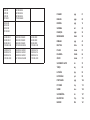
SMALL

40/180 M
60/180 M
80/180 M
110/180 M
40/180 SAN M
60/180 SAN M
80/180 SAN M
110/180 SAN M
40/180 XM
60/180 XM
80/180 XM
110/180 XM
B 40/220.32 M
B 60/220.32 M
B 80/220.32 M
B 110/220.32 M
B 40/220.32 SAN M
B 60/220.32 SAN M
B 80/220.32 SAN M
B 110/220.32 SAN M
D 40/220.32 M
D 60/220.32 M
D 80/220.32 M
D 110/220.32 M
B 40/250.40 M
B 60/250.40 M
B 80/250.40 M
B 110/250.40 M
B 40/250.40 SAN M
B 60/250.40 SAN M
B 80/250.40 SAN M
B 110/250.40 SAN M
D 40/250.40 M
D 60/250.40 M
D 80/250.40 M
D 110/250.40 M
ITALIANO
ENGLISH
ESPAÑOL
SVENSKA
FRANÇAIS
NEDERLANDS
ROMANA
DEUTSCH
POLSKI
ΕΛΛΗΝΙΚΑ
ČESKY
SLOVENSKÝ JAZYK
TÜRÇE
LATVIEŠU
LIETUVIŠKAI
PORTUGUÊS
РУССКИЙ
SUOMI
SLOVENŠČINA
БЪЛГАРСКИ
MAGYAR
pag.
page
pág
sid
page
bladz
pag.
Seite
strona
Σελίδα
strana
str.
say
lpp.
psl.
pág
стр.
sivu
str.
Стр.
Old.
01
08
15
22
30
36
43
50
57
64
71
78
85
92
99
106
113
120
127
134
141

1A
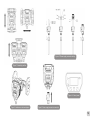
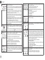
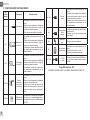
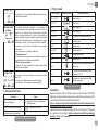
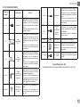
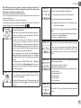
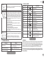
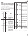
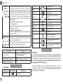
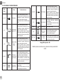
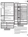
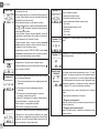
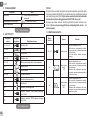
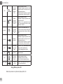
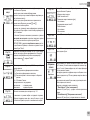
Figure 2: Installation on horizontal pipes
Figure 4: Power supply connector connection
Figure 5: Control panel
Figure 3: Power supply connector wiring
Figure 1: Assembly position

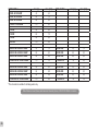
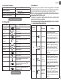
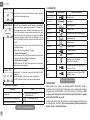
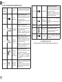
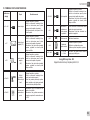
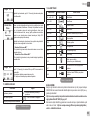
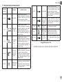
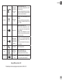
EVOPLUS SMALL Hmax [m] Qmax [m3/h] EVOPLUS SMALL Hmax [m] Qmax [m3/h]
40/180 M - 40/180 SAN M* 4,0 6,0
60/180 M - 60/180 SAN M* 6,0 7,0
80/180 M - 80/180 SAN M* 8,0 8,0
110/180 M - 110/180 SAN M* 11,0 9,0
40/180 XM 4,0 6,0
60/180 XM 6,0 7,2
80/180 XM 8,0 8,2
110/180 XM 11,0 10,0
B 40/220.32 M - B 40/220.32 SAN M* 4,0 7,4 D 40/220.32 M 4,0 7,0
B 60/220.32 M - B 60/220.32 SAN M* 6,0 9,0 D 60/220.32 M 6,0 8,0
B 80/220.32 M - B 80/220.32 SAN M* 8,0 10,0 D 80/220.32 M 8,0 9,0
B 110/220.32 M - B 110/220.32 SAN M* 11,0 11,0 D 110/220.32 M 11,0 10,0
B 40/250.40 M - B 40/250.40 SAN M* 4,0 8,4 D 40/250.40 M 4,0 8,0
B 60/250.40 M - B 60/250.40 SAN M* 6,0 9,8 D 60/250.40 M 6,0 9,0
B 80/250.40 M - B 80/250.40 SAN M* 8,0 10,8 D 80/250.40 M 8,0 10,0
B 110/250.40 M - B 110/250.40 SAN M* 11,0 12,0 D 110/250.40 M 11,0 11,2
*This circulator is suitable for drinking water only.
Table: Maximum head (Hmax) and maximum ow rate (Qmax) of EVOPLUS SMALL circulators
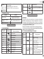
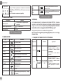
2A

3A
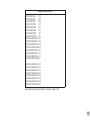
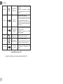
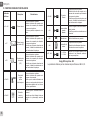
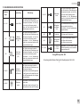
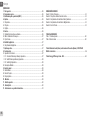
Energy Efciency Index - EEI
EVOPLUS 40/180 M 0,23
EVOPLUS 60/180 M 0,22
EVOPLUS 80/180 M 0,22
EVOPLUS 110/180 M 0,22
EVOPLUS 40/180 XM 0,21
EVOPLUS 60/180 XM 0,21
EVOPLUS 80/180 XM 0,21
EVOPLUS 110/180 XM 0,21
EVOPLUS B 40/220.32 M 0,22
EVOPLUS B 60/220.32 M 0,22
EVOPLUS B 80/220.32 M 0,22
EVOPLUS B 110/220.32 M 0,22
EVOPLUS B 40/250.40 M 0,21
EVOPLUS B 60/250.40 M 0,21
EVOPLUS B 80/250.40 M 0,21
EVOPLUS B 110/250.40 M 0,21
EVOPLUS D 40/220.32 M 0,23
EVOPLUS D 60/220.32 M 0,23
EVOPLUS D 80/220.32 M 0,23
EVOPLUS D 110/220.32 M 0,23
EVOPLUS D 40/250.40 M 0,22
EVOPLUS D 60/250.40 M 0,22
EVOPLUS D 80/250.40 M 0,22
EVOPLUS D 110/250.40 M 0,22
The benchmark for the most efcient circulators is EEI ≤ 0,20.

ITALIANO
IT
1
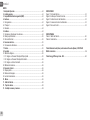
INDICE
1. Avvertenze Particolari ............................................................................................. 2
2. Liquidi Pompati ........................................................................................................ 2
3. Compatibilità Elettromagnetica (EMC) .................................................................. 2
4. Gestione ................................................................................................................... 2
4.1 Immagazzinaggio .................................................................................................... 2
4.2 Trasporto ................................................................................................................. 2
4.3 Peso ........................................................................................................................ 2
5. Installazione ............................................................................................................. 2
5.1 Installazione e Manutenzione Del Circolatore ......................................................... 2
5.2 Rotazione Delle Teste Motore ................................................................................. 3
5.3 Valvola Di Non Ritorno ............................................................................................ 3
6. Collegamenti Elettrici .............................................................................................. 3
6.1 Collegamento Di Alimentazione ............................................................................... 3
7. Avviamento .............................................................................................................. 3
8. Funzioni ..................................................................................................................... 3
8.1 Modi Di Regolazione ...............................................................................................3
8.1.1 Regolazione a Pressione Differenziale Proporzionale.......................................3
8.1.2 Regolazione a Pressione Differenziale Costante ..............................................4
8.1.3 Regolazione a Curva Costante ..........................................................................4
8.2 Moduli di espansione ...............................................................................................3
9. Pannello Di Controllo .............................................................................................. 4
9.1 Display Graco ........................................................................................................ 4
9.2 Tasti Di Navigazione ................................................................................................ 4
9.3 Luci Di Segnalazione ...............................................................................................4
10. Menù ....................................................................................................................... 4
11. Impostazioni di fabbrica ........................................................................................ 6
12. Tipi di allarme ........................................................................................................ 6
13. Condizioni di errore e ripristino ........................................................................... 6
INDICE DELLE FIGURE
Figura 1: Posizione di montaggio .................................................................................1A
Figura 2: Installazione su Tubazioni Orizzontali ............................................................1A
Figura 3: Cablaggio Connettore di Alimentazione .........................................................1A
Figura 4: Connessione Connettore di Alimentazione ....................................................1A
Figura 5: Pannello di Controllo ......................................................................................1A
INDICE TABELLE
Tabella 1: Impostazioni di Fabbrica ................................................................................ 6
Tabella 2: Elenco Allarmi ............................................................................................... 6
Table: Maximum head (Hmax) and maximum ow rate (Qmax) of EVOPLUS
SMALL circulators ....................................................................................................... 2A
Table: Energy Efciency Index - EEI ..........................................................................3A

ITALIANO
IT
2
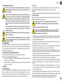
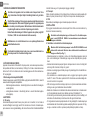
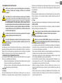
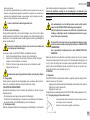
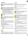
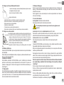
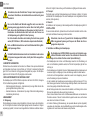
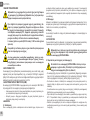
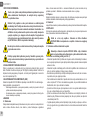
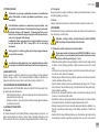
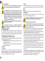
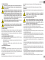
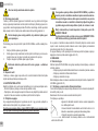
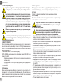
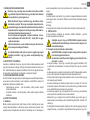
1. AVVERTENZE PARTICOLARI
Vericare che il prodotto non abbia subito danni dovuti al trasporto o
al magazzinaggio. Controllare che l’involucro esterno sia integro ed in
ottime condizioni.
Prima di intervenire sulla parte elettrica o meccanica dell’impianto to-
gliere sempre la tensione di rete. Attendere lo spegnimento delle spie
luminose sul pannello di controllo prima di aprire l’apparecchio stesso.
Il condensatore del circuito intermedio in continua resta carico con ten-
sione pericolosamente alta anche dopo la disinserzione della tensione
di rete.
Sono ammissibili solo allacciamenti di rete saldamente cablati. L’ap-
parecchio deve essere messo a terra (IEC 536 classe 1, NEC ed altri
standard al riguardo).
Morsetti di rete e i morsetti motore possono portare tensione pericolosa
anche a motore fermo.
Se il cavo di alimentazione è danneggiato, esso deve essere sostituito
dal servizio assistenza tecnica o da personale qualicato, in modo da
prevenire ogni rischio.
2. LIQUIDI POMPATI
La macchina è progettata e costruita per pompare acqua, priva di sostanze esplosive e
particelle solide o bre, con densità pari a 1000 Kg/m³, viscosità cinematica uguale ad
1mm²/s e liquidi non chimicamente agressivi. È possibile utilizzare glicole etilenico in
percentuale non superiore al 30%.
3. COMPATIBILITÀ ELETTROMAGNETICA (EMC)
I circolatori EVOPLUS SMALL rispettano la norma EN 61800-3, nella ca-
tegoria C2, per la compatibilità elettromagnetica.
- Emissioni elettromagnetiche – Ambiente industriale (in alcuni casi possono essere
richieste misure di contenimento).
- Emissioni condotte – Ambiente industriale (in alcuni casi possono essere richieste
misure di contenimento).
4. GESTIONE
4.1 Immagazzinaggio
Tutti i circolatori devono essere immagazzinati in luogo coperto, asciutto e con umidità
dell’aria possibilmente costante, privo di vibrazioni e polveri. Vengono forniti nel loro im-
ballo originale nel quale devono rimanere no al momento dell’installazione. Se così non
fosse provvedere a chiudere accuratamente la bocca di aspirazione e mandata.
4.2 Trasporto
Evitare di sottoporre i prodotti ad inutili urti e collisioni. Per sollevare e trasportare il circo-
latore avvalersi di sollevatori utilizzando il pallet fornito di serie (se previsto).
4.3 Peso
La targhetta adesiva posta sull’imballo riporta l’indicazione del peso totale del circolatore.
5. INSTALLAZIONE
Seguire attentamente le raccomandazioni di questo capitolo per realizzare una corretta
installazione elettrica idraulica e meccanica.
Accertarsi che la tensione e la frequenza di targa del circolatore
EVOPLUS SMALL corrispondano a quelle della rete di alimentazione.
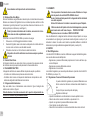
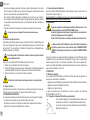
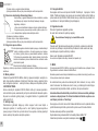
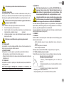
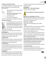
5.1 Installazione e Manutenzione Del Circolatore
Montare il circolatore EVOPLUS SMALL sempre con l’albero motore in
posizione orizzontale. Montare il dispositivo di controllo elettronico in
posizione verticale (si veda Figura 1)
- Il circolatore può essere installato negli impianti di riscaldamento e condizionamento
sia sulla tubazione di mandata che su quella di ritorno; la freccia stampata sul corpo
pompa indica la direzione del usso.
- Installare per quanto possibile il circolatore sopra il livello minimo della caldaia, ed il più
lontano possibile da curve, gomiti e derivazioni.
- Per facilitare le operazioni di controllo e manutenzione, installare sia sul condotto di
aspirazione che su quello di mandata una valvola di intercettazione.
- Prima di installare il circolatore, effettuare un accurato lavaggio dell’impianto con sola
acqua ad 80°C. Quindi scaricare completamente l’impianto per eliminare ogni eventua-
le sostanza dannosa che fosse entrata in circolazione.
- Eseguire il montaggio in modo da evitare gocciolamenti sul motore e sul dispositivo di
controllo elettronico sia in fase di installazione sia in fase di manutenzione.
- Evitare di mescolare all’acqua in circolazione additivi derivanti da idrocarburi e prodotti
aromatici. L’aggiunta di antigelo, dove necessario, si consiglia nella misura massima
del 30%.
- In caso di coibentazione (isolamento termico) utilizzare l’apposito kit (se fornito in do-
tazione) ed accertarsi che i fori di scarico condensa della cassa motore non vengano
chiusi o parzialmente ostruiti.
- Per garantire massima efcienza dell’impianto e una lunga vita al circolatore si consi-
glia l’utilizzo di ltri defangatori magnetici per separare e raccogliere eventuali impurità
presenti nell’impianto stesso (particelle di sabbia, particelle di ferro e fanghi).
- Nel caso di manutenzione utilizzare sempre un set di guarnizioni nuove.

ITALIANO
IT
3
Non coibentare mai il dispositivo di controllo elettronico.
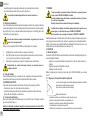
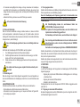
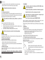
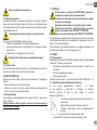
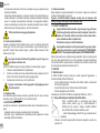
5.2 Rotazione Delle Teste Motore
Nel caso l’installazione venga effettuata su tubazioni poste in orizzontale sarà necessario
effettuare una rotazione di 90 gradi del motore con relativo dispositivo elettronico al ne
di mantenere il grado di protezione IP e per permettere all’utente un’interazione con l’in-
terfaccia graca più confortevole (si veda Figura 2).
Prima di procedere alla rotazione del circolatore, assicurarsi che il circo-
latore stesso sia stato completamente svuotato.
Per ruotare il circolatore EVOPLUS SMALL procedere come segue:
1. Rimuovere le 4 viti di ssaggio della testa del circolatore.
2. Ruotare di 90 gradi la cassa motore insieme al dispositivo di controllo elettronico
in senso orario o antiorario a seconda della necessità.
3. Rimontare ed avvitare le 4 viti che ssano la testa del circolatore.
Il dispositivo di controllo elettronico deve rimanere sempre in posizione
verticale!
5.3 Valvola Di Non Ritorno
Se l’impianto è dotato di una valvola di non ritorno, assicurarsi che la pressione minima
del circolatore sia sempre superiore alla pressione di chiusura della valvola.
6. COLLEGAMENTI ELETTRICI
I collegamenti elettrici devono essere effettuati da personale esperto e qualicato.
-Il circolatore non richiede alcuna protezione esterna del motore.
-Controllare che la tensione e la frequenza di alimentazione corrispondano ai valori
indicati sulla targhetta di identicazione del circolatore.
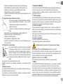
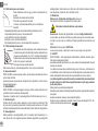
6.1 Collegamento di Alimentazione
Dopo aver cablato il cavo di alimentazione come mostrato in Figura 3 collegarlo alla
scheda come mostrato in Figura 4.
Prima di alimentare il circolatore assicurarsi che il coperchio del pannello di con-
trollo EVOPLUS SMALL sia perfettamente chiuso!
7. AVVIAMENTO
Tutte le operazioni di avviamento devono essere effettuate con il coper-
chio del pannello di controllo EVOPLUS SMALL chiuso!
Avviare il sistema soltanto quando tutti i collegamenti elettrici ed idraulici
sono stati completati.
Evitare di far funzionare il circolatore in assenza di acqua nell’impianto.
Il uido contenuto nell’impianto oltre che ad alta temperatura e pressione
può trovarsi anche sotto forma di vapore. PERICOLO USTIONI!
È pericoloso toccare il circolatore. PERICOLO USTIONI!
Una volta effettuati tutti i collegamenti elettrici ed idraulici riempire l’impianto con acqua
ed eventualmente con glicole (per la percentuale massima di glicole si veda par. 2) ed
alimentare il sistema. Una volta avviato il sistema è possibile modicare le modalità di
funzionamento per meglio adattarsi alle esigenze dell’impianto (si veda par.10).
8. FUNZIONI
8.1 Modi Di Regolazione
I circolatori EVOPLUS SMALL consentono di effettuare le seguenti modalità di regolazio-
ne a seconda delle necessità dell’impianto:
- Regolazione a pressione differenziale proporzionale in funzione del usso pre-
sente nell’impianto.
- Regolazione a pressione differenziale costante.
- Regolazione a curva costante.
La modalità di regolazione può essere impostata attraverso il pannello di controllo EVO-
PLUS SMALL (si veda par. 10).
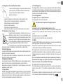
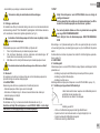
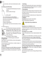
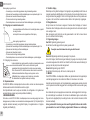
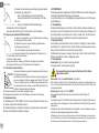
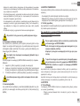
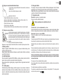
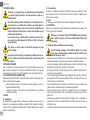
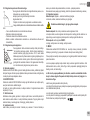
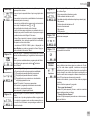
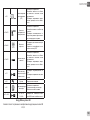
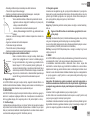
8.1.1 Regolazione a Pressione Differenziale Proporzionale
In questa modalità di regolazione la pressione differenziale viene
ridotta o aumenta al diminuire o all’aumentare della richiesta d’ac-
qua.
Il set-point Hs può essere impostato da display.
Regolazione indicata per:
- Impianti di riscaldamento e condizionamento con elevate perdite di carico.
- Sistemi a due tubi con valvole termostatiche e prevalenza ≥ 4 m.
- Impianti con regolatore di pressione differenziale secondario.
- Circuiti primari con alte perdite di carico.
- Sistemi di ricircolo sanitario con valvole termostatiche sulle colonne montanti.

ITALIANO
IT
4
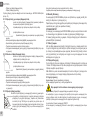
8.1.2 Regolazione a Pressione Differenziale Costante
In questa modalità di regolazione la pressione differenziale viene
mantenuta costante, indipendentemente dalla richiesta d’acqua.
Il set-point Hs può essere impostato da display.
Regolazione indicata per:
- Impianti di riscaldamento e condizionamento con basse perdite di carico.
- Sistemi a due tubi con valvole termostatiche e prevalenza ≤ 2 m.
- Sistemi monotubo con valvole termostatiche.
- Impianti a circolazione naturale.
- Circuiti primari con basse perdite di carico.
- Sistemi di ricircolo sanitario con valvole termostatiche sulle colonne montanti.
8.1.3 Regolazione a Curva Costante
In questa modalità di regolazione il circolatore lavora su curve ca-
ratteristiche a velocità costante. La curva di funzionamento viene
selezionata impostando la velocità di rotazione attraverso un fattore
percentuale. Il valore 100% indica la curva limite massimo. La velo-
cità di rotazione effettiva può dipendere dalle limitazioni di potenza e
di pressione differenziale del proprio modello di circolatore.
La velocità di rotazione può essere impostata da display. Regolazio-
ne indicata per impianti di riscaldamento e condizionamento a portata costante.
8.2 Moduli Di Espansione
I circolatori EVOPLUS SMALL possono essere dotati di alcuni moduli di espansione che
permettono di ampliarne le funzionalità.
Per i dettagli sulle modalità di installazione, congurazione ed utilizzo dei moduli di
espansione si rimanda al manuale specico.
9. PANNELLO DI CONTROLLO
Le funzionalità dei circolatori EVOPLUS SMALL possono essere modicate tramite il
pannello di controllo posto sul coperchio del dispositivo di controllo elettronico.
Sul pannello sono presenti: un display graco, 4 tasti di navigazione e 3 luci LED di
segnalazione (si veda Figura 5).
9.1 Display Graco
Attraverso il display graco sarà possibile navigare all’interno di un menù in modo facile
ed intuitivo che permetterà di vericare e modicare le modalità di funzionamento del
sistema ed il set-point di lavoro. Sarà inoltre possibile visualizzare lo stato del sistema e
lo storico di eventuali allarmi memorizzati dal sistema stesso.
H
Q
limitemassimo
9.2 Tasti Di Navigazione
Per navigare all’interno del menù sono messi a disposizione 4 tasti: 3 tasti sotto il display
e 1 laterale. I tasti sotto il display sono denominati tasti attivi e il tasto laterale è denomi-
nato tasto nascosto. Ogni pagina del menù è fatta in modo tale da indicare la funzione
associata ai 3 tasti attivi (quelli sotto il display).
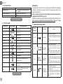
9.3 Luci Di Segnalazione
Luce gialla: Segnalazione di sistema alimentato.
Se accesa signica che il sistema è alimentato.
Non rimuovere mai il coperchio se la luce gialla è accesa.
Luce rossa: Segnalazione di allarme/anomalia presente nel sistema.
Se la luce lampeggia allora l’allarme non è bloccante e la pompa può essere pilotata
comunque. Se la luce è ssa allora l’allarme è bloccante e la pompa non può essere
pilotata.
Luce verde: Segnalazione di pompa ON/OFF.
Se accesa, la pompa sta girando. Se spenta la pompa è ferma.
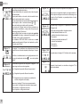
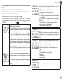
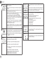
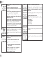
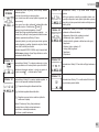
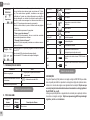
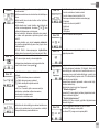
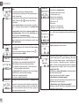
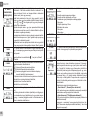
10. MENÙ
I circolatori EVOPLUS SMALL mettono a disposizione un menù utente accessibile dalla
Home Page premendo e rilasciando il tasto centrale “Menu”.
Di seguito sono rappresentate le pagine del menù utente attraverso le quali è possibile
vericare lo stato del sistema e modicarne le impostazioni.
Se le pagine dei menù mostrano una chiave in basso a sinistra signica che non è possi-
bile modicare le impostazioni. Per sbloccare i menù andare nella Home Page e premere
contemporaneamente il tasto nascosto e il tasto sotto la chiave no a che la chiave non
scompare.
Se non viene premuto nessun tasto per 60 minuti le impostazioni si bloccano au-
tomaticamente ed il display viene spento. Alla pressione di un tasto qualsiasi il
display viene riacceso e viene visualizzata la “Home Page”.
Per navigare all’interno dei menù premere il tasto centrale.
Per tornare alla pagina precedente tenere premuto il tasto nascosto, quindi premere e
rilasciare il tasto centrale.11. Per modicare le impostazioni utilizzare i tasti sinistro e
destro.
Per confermare la modica di un’impostazione premere per 3 secondi il tasto centrale
“OK”. L’avvenuta conferma verrà evidenziata con la seguente icona:

ITALIANO
IT
5
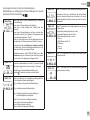
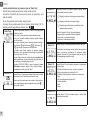
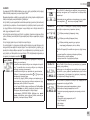
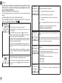
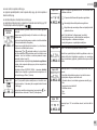
Home Page
Nell’Home Page sono riassunte in modo grafico le principali
impostazioni del sistema.
L’icona in alto a sinistra indica il tipo di regolazione selezionata.
L’icona in alto al centro indica la modalità di funzionamento se-
lezionata (auto o economy)
L’icona in alto a destra indica la presenza di un inverter singolo
oppure gemellare. La rotazione dell’icona o segnala
quale pompa di circolazione è in funzione.
Al centro della Home Page si trova un parametro di sola visua-
lizzazione che può essere scelto fra un piccolo set di parametri
attraverso la Pagina 9.0 del menù.
Dalla Home Page è possibile accedere alla pagina di regola-
zione del contrasto del display: tenendo premuto il tasto na-
scosto, quindi premere e rilasciare il tasto destro.
I circolatori EVOPLUS SMALL mettono a disposizione un menù
utente accessibile dalla Home Page premendo e rilasciando il
tasto centrale Menu”.
Pagina 1.0
Attraverso la Pagina 1.0 si settano le impostazioni di fabbrica
premendo contemporaneamente per 3 secondi i tasti sinistro
e destro.
L’avvenuto ripristino delle impostazioni di fabbrica verrà noti-
cato con la comparsa del simbolo vicino alla scritta “Default”.
Pagina 2.0
Attraverso la Pagina 2.0 si imposta la modalità di regolazione.
Si possono scegliere fra le seguenti modalità:
1 = Regolazione a pressione differenziale proporzionale.
2 = Regolazione a pressione differenziale costante.
3 = Regolazione a curva costante con velocità di rotazione
impostata da display.
La pagina 2.0 visualizza 3 icone che rappresentano:
- icona centrale = impostazione attualmente selezionata;
- icona destra = impostazione successiva;
- icona sinistra = impostazione precedente.
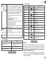
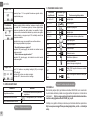
Pagina 3.0
Attraverso la Pagina 3.0 è possibile modicare il set-point di
regolazione. A seconda del tipo di regolazione scelto nella pa-
gina precedente, il set-point da impostare sarà una prevalenza
oppure, nel caso di Curva Costante, una percentuale relativa
alla velocità di rotazione.
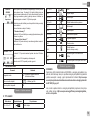
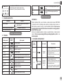
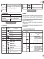
Pagina 9.0
Attraverso la pagina 9.0 si può scegliere il parametro da visua-
lizzare nella Home Page:
H: Prevalenza misurata espressa in metri
Q: Portata stimata espressa in m3/h
S: Velocità di rotazione espressa in giri al minuto (rpm)
E: Non presente
P: Potenza erogata espressa in kW
h: Ore di funzionamento
T: Non presente
T1: Non presente
Pagina 10.0
Attraverso la pagina 10.0 si può scegliere la lingua con cui vi-
sualizzare i messaggi.
Pagina 11.0
Attraverso la pagina 11.0 si può visualizzare lo storico allarmi
premendo il tasto destro.
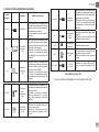
Storico Allarmi
Se il sistema rileva delle anomalie le registra in modo perma-
nente nello storico degli allarmi (per un massimo di 15 allarmi).
Per ogni allarme registrato si visualizza una pagina costituita da
3 parti: un codice alfanumerico che identica il tipo di anomalia,
un simbolo che illustra in modo graco l’anomalia e inne un
messaggio nella lingua selezionata alla Pagina 10.0 che descri-
ve brevemente l’anomalia. Premendo il tasto destro si possono
scorrere tutte le pagine dello storico.
Al termine dello storico compaiono 2 domande:
1.“Resettare Allarmi?”
Premendo OK (tasto sinistro) si resettano gli eventuali allarmi
ancora presenti nel sistema.
2.“Cancellare Storico Allarmi?”
Premendo OK (tasto sinistro) si cancellano gli allarmi memo-
rizzati nello storico.
Pagina 13.0
Attraverso la pagina 13.0 si può impostare il sistema nello stato
ON oppure OFF.
Se si seleziona ON la pompa è sempre accesa.
Se si seleziona OFF la pompa è sempre spenta.

ITALIANO
IT
6
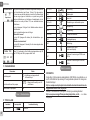
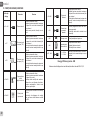
11. IMPOSTAZIONI DI FABBRICA
Parametro Valore
Modalità di regolazione
= Regolazione a pressione differenzia
le proporzionale
Modalità di funzionamento gemellare = Alternato ogni 24h
Comando avviamento pompa ON
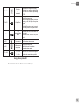
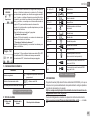
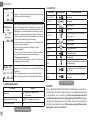
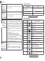
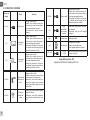
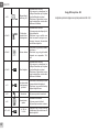
12. TIPI DI ALLARME
Codice Allarme Simbolo Allarme Descrizione Allarme
e0 - e16; e21 Errore Interno
e17 - e19 Corto Circuito
e20 Errore Tensione
e22 - e31 Errore Interno
e32 - e35
Sovratemperatura del sistema elet-
tronico
e37 Tensione bassa
e38 Tensione alta
e39 - e40 Pompa bloccata
e46 Pompa scollegata
e42 Marcia a secco
e56
Sovratemperatura motore (intervento
motoprotettore)
e57
Frequenza del segnale esterno PWM
minore di 100 Hz
e58
Frequenza del segnale esterno PWM
maggiore di 5 kHz
Tabella 1: Impostazioni di fabbrica
Tabella 2: Elenco allarmi
INFORMAZIONI
Domande frequenti (FAQ) riguardanti la direttiva sulla progettazione ecocompatibile
2009/125/CE che stabilisce un quadro per l’elaborazione di speciche per la progettazio-
ne ecocompatibile di prodotti connessi all’energia e suoi regolamenti attuativi:
http://ec.europa.eu/enterprise/policies/sustainable-business/documents/eco-de-
sign/guidance/les/20110429_faq_en.pdf
Linee guida che accompagnano i regolamenti della commissione per l’applicazione della
direttiva sulla progettazione ecocompatibile:
http://ec.europa.eu/energy/efciency/ecodesign/legislation_en.htm - v. circolatori.
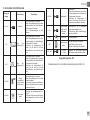
13. CONDIZIONE DI ERRORE E RIPRISTINO
Indicazione
display
Descrizione Ripristino
e0 – e16 Errore interno
- Togliere tensione al sistema.
- Attendere lo spegnimento delle spie lu-
minose sul pannello di controllo quindi
alimentare nuovamente il sistema.
- Se l’errore persiste, sostituire il circo-
latore.
e37
Bassa tensione
di rete (LP)
- Togliere tensione al sistema.
- Attendere lo spegnimento delle spie lu-
minose sul pannello di controllo quindi
alimentare nuovamente il sistema.
- Controllare che la tensione di rete sia
corretta, eventualmente ripristinarla ai
dati di targa.
e38
Alta
tensione
di rete (HP)
- Togliere tensione al sistema.
- Attendere lo spegnimento delle spie lu-
minose sul pannello di controllo quindi
alimentare nuovamente il sistema.
- Controllare che la tensione di rete sia
corretta, eventualmente ripristinarla ai
dati di targa.
e32-e35
Surriscalda-
mento critico
parti
elettroniche
- Togliere tensione al sistema.
- Attendere lo spegnimento delle spie lu-
minose sul pannello di controllo.
- Vericare che i condotti di areazione
del sistema non siano ostruiti e che la
temperatura ambiente del locale sia in
specica.

ITALIANO
IT
7
e39-e40
Protezione da
sovracorrente
- Controllare che il circolatore giri libe-
ramente.
- Controllare che l’aggiunta di antigelo
non sia superiore alla misura massima
del 30%.
e21-e30
Errore di
tensione
- Togliere tensione al sistema.
- Attendere lo spegnimento delle spie lu-
minose sul pannello di controllo quindi
alimentare nuovamente il sistema.
- Controllare che la tensione di rete sia
corretta, eventualmente ripristinarla ai
dati di targa.
e31
Comunicazione
gemellare
assente
- Vericare l’integrità del cavo di comuni-
cazione gemellare.
- Controllare che entrambi i circolatori
siano alimentatati.
e42 Marcia a secco - Mettere l’impianto in pressione.
e56
Sovratempera-
tura del motore
- Togliere tensione al sistema.
- Attendere il raffreddamento del motore
- Alimentare nuovamente il sistema
e57 ; e58
f < 100 Hz
f > 5 kHz
Controllare che il segnale esterno PWM
sia f unzionante e collegato come da
specica.
Energy Efciency Index - EEI
Il parametro di riferimento per i circolatori più efcienti è EEI ≤ 0,20

ENGLISH
GB
8
INDEX
1. Particular warnings ................................................................................................. 9
2. Pumped liquids ........................................................................................................ 9
3. Electromagnetic Compatibility (EMC) ................................................................... 9
4. Management ............................................................................................................. 9
4.1 Storage .................................................................................................................... 9
4.2 Transport ................................................................................................................. 9
4.3 Weight ..................................................................................................................... 9
5. Installation ................................................................................................................ 9
5.1 Circular Installation and Maintenance ..................................................................... 9
5.2 Rotation of the Motor Heads ...................................................................................10
5.3 Non-return valve ..................................................................................................... 10
6. Electrical connections ...........................................................................................10
6.1 Power supply connection ........................................................................................10
7. Start .........................................................................................................................10
8. Functions .................................................................................................................10
8.1 Regulating Modes ...................................................................................................10
8.1.1 Regulation with Proportional Differential Pressure ...........................................10
8.1.2 Regulation with Constant Differential Pressure ................................................11
8.1.3 Regulation with constant curve .........................................................................11
8.2 Expansion Modules ................................................................................................11
9. Control Panel ..........................................................................................................11
9.1 Graphic Display ......................................................................................................11
9.2 Navigation Buttons .................................................................................................11
9.3 Warning Lights ........................................................................................................ 11
10. Menus ....................................................................................................................11
11. Factory settings .................................................................................................... 13
12. TypeS of Alarm ......................................................................................................13
13. Error Condition And Reset ..................................................................................13
INDEX OF FIGURES
Figure 1: Assembly position ..........................................................................................1A
Figure 2: Installation on horizontal pipes .......................................................................1A
Figure 3: Power supply connector wiring .......................................................................1A
Figure 4: Power supply connector connection ...............................................................1A
Figure 5: Control panel ..................................................................................................1A
INDEX OF TABLES
Table 1: Factory settings ................................................................................................13
Table 2: List of alarms ....................................................................................................13
Table: Maximum head (Hmax) and maximum ow rate (Qmax) of EVOPLUS
SMALL circulators ....................................................................................................... 2A
Table: Energy Efciency Index - EEI ..........................................................................3A

ENGLISH
GB
9
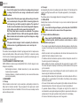
1. PARTICULAR WARNINGS
Ensure that the product has not suffered any damage during transport
or storage. Check that the outer casing is unbroken and in excellent
conditions.
Always switch off the mains power supply before working on the electri-
cal or mechanical part of the system. Wait for the warning lights on the
control panel to go out before opening the appliance. The capacitor of
the direct current intermediate circuit remains charged with dangerous-
ly high voltage even after the mains power has been turned off.
Only rmly cabled mains connections are admissible. The appliance
must be earthed (IEC 536 class 1, NEC and other applicable standards).
Mains terminals and motor terminals may still have dangerous voltage
when the motor is stopped.
If the power cable is damaged, it must be replaced by the technical as-
sistance service or by qualied personnel, so as to avoid any risk.
2. PUMPED LIQUIDS
The machine has been designed and made for pumping water, free from explosive sub-
stances and solid particles or bres, with a density of 1000 Kg/m³, a kinematic viscosity
of 1mm²/s and non chemically aggressive liquids. It is possible to use ethylene glycol in a
percentage of no more than 30%.
3. ELECTROMAGNETIC COMPATIBILITY (EMC)
EVOPLUS SMALL circulators respect standard EN 61800-3, in the C2 category, for elec-
tromagnetic compatibility.
- Electromagnetic emissions - Industrial environment (in some cases restrictive
measures may be requested).
- Conducted emissions - Industrial environment (in some cases restrictive meas-
ures may be requested).
4. MANAGEMENT
4.1 Storage
All the circulators must be stored in a dry covered place, with possibly constant air hu-
midity, free from vibrations and dust. They are supplied in their original pack in which
they must remain until the time of installation. If this is not the case, accurately close the
suction and delivery mouth.
4.2 Transport
Avoid subjecting the products to needless impacts and collisions. To lift and transport the
circulator use lifting devices with the aid of the pallet supplied with it (if contemplated).
4.3Weight
The adhesive plate on the packaging indicates the total weight of the circulator.
5. INSTALLATION
Carefully follow the advice in this chapter to carry out correct electrical, hydraulic and
mechanical installation.
Ensure that the voltage and frequency on the data plate of the EVOPLUS
SMALL circulator are the same as those of the power mains.
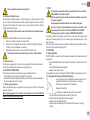
5.1 Circular Installation and Maintenance
Always install the EVOPLUS SMALL circulator with the motor shaft in
a horizontal position. Install the electronic control device in a vertical
position (see Figure 1)
- The circulator may be installed in heating and conditioning systems on either the deliv-
ery pipe or the return pipe; the arrow marked on the pump body indicates the direction
of ow.
- Install the circulator as far as possible above the minimum boiler level and as far as
possible from bends, elbows and junction boxes.
- To facilitate control and maintenance operations, install an interception valve both on
the suction pipe and on the delivery pipe.
- Before installing the circulator, accurately ush the system with only water at 80°C.
Then drain the system completely to eliminate any harmful substance that may have
got into circulation.
- Assemble in such a way as to avoid dripping on the motor and on the electronic control
device during both installation and maintenance.
- Avoid mixing additives derived from hydrocarbons and aromatic products with the cir-
culating water. It is recommended that the addition of antifreeze, where necessary,
should not exceed 30%.
- In the event of heat insulation use the special kit (if provided) and ensure that the con-
densate draining holes in the motor casing are not closed or partly blocked.
- To guarantee maximum efciency of the system and long life of the circulator it is
recommended to use magnetic sludge-removing lters to separate and collect any im-
purities present in the system (particles of sand, particles of iron and sludge).
- In the case of maintenance, always use a set of new gaskets.

ENGLISH
GB
10
Never insulate the electronic control device.
5.2 Rotation of the Motor Heads
If the circulator is installed on pipes in a horizontal position, it will be necessary to rotate
the motor with the respective electronic device through 90 degrees in order to maintain
the grade of IP protection and to allow the user a more convenient interaction with the
graphic interface (see Figure 2).
Before rotating the circulator, ensure that it has been completely drained.
To rotate the EVOPLUS SMALL circulator, proceed as follows:
1. Remove the 4 xing screws of the circulator head.
2. Rotate the motor casing with the electronic control device through 90 degrees
clockwise or counterclockwise, as necessary.
3. Reassemble and tighten the 4 screws that x the circulator head.
The electronic control device must always remain in vertical position!
5.3 Non-return valve
If the system is equipped with a non-return valve, ensure that the minimum pressure of
the circulator is always higher than the valve closing pressure.
6. ELECTRICAL CONNECTIONS
The electrical connections must be made by expert, qualied personnel.
-The circulator does not require any external motor protection.
-Ensure that the supply voltage and frequency are the same as the values indicated on
the electrical data plate of the circulator.
6.1 Power supply connection
After having wired the power supply cable as shown in Figure 3, connect it to the board
as shown in Figure 4.
Before supplying power to the circulator, ensure that the cover of the EVOPLUS
SMALL control panel is perfectly closed!
7. START
All the starting operations must be performed with the cover of the EV-
OPLUS SMALL control panel closed!
Start the system only when all the electrical and hydraulic connections
have been completed.
Avoid running the circulator when there is no water in the system.
As well as being at a high temperature and pressure, the uid in the
system may also be in the form of steam. DANGER OF SCALDING!
It is dangerous to touch the circulator. DANGER OF SCALDING!
Once all the electrical and hydraulic connections have been made, ll the system with
water and if necessary with glycol (for the maximum glycol percentage see par. 2) and
feed the system.
Once the system has been started it is possible to modify the operating modes to adapt
better to the plant requirements (see par.10).
8. FUNCTIONS
8.1 Regulating Modes
EVOPLUS SMALL circulators allow the following regulating modes depending on plant
requirements:
- Proportional differential pressure regulation depending on the ow present in the
plant.
- Constant differential pressure regulation.
- Regulation with constant curve.
The regulating mode may be set through the EVOPLUS SMALL control panel (see par. 10).
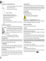
8.1.1 Regulation with Proportional Differential Pressure
In this regulating mode the differential pressure is reduced or in-
creased as the demand for water decreases or increases.
The Hs set point may be set from the display.
Regulation indicated for:
- Heating and conditioning plants with high load losses.
- Two-pipe systems with thermostatic valves and head ≥ 4 m.
- Plants with secondary differential pressure regulator.
- Primary circuits with high load losses.
- Domestic water recirculating systems with thermostatic valves on the rising
columns.

ENGLISH
GB
11
8.1.2 Regulation with Constant Differential Pressure
In this regulating mode the differential pressure is kept constant,
irrespective of the demand for water,
The Hs set point may be set from the display.
Regulation indicated for:
- Heating and conditioning plants with low load losses.
- Two-pipe systems with thermostatic valves and head ≤ 2 m.
- Single-pipe systems with thermostatic valves.
- Plants with natural circulation.
- Primary circuits with low load losses.
- Domestic water recirculating systems with thermostatic valves on the rising col-
umns.
8.1.3 Regulation with constant curve
In this regulating mode the circulator works on characteristic curves
at a constant speed. The operating curve is selected by setting
the rotation speed through a percentage factor. The value 100%
indicates the maximum limit curve. The actual rotation speed may
depend on the power and differential pressure limits of your circu-
lator model.
The rotation speed may be set from the display.
Regulation indicated for heating and conditioning plants with constant ow.
8.2 Expansion Modules
EVOPLUS SMALL circulators may be equipped with some expansion modules that allow
their functions to be increased. For details on the procedures for installation, conguration
and use of the expansion modules, see the specic manual.
9. CONTROL PANEL
The functions of EVOPLUS SMALL circulators can be modied by means of the control panel
on the cover of the electronic control device. On the panel there are: a graphic display, 4
navigation keys and 3 LED warning lights (see Figure 5).
9.1 Graphic Display
Using the graphic display it will be possible to navigate in an easy and intuitive menu
which will enable you to check and modify the system operating mode and the working
set-point. It will also be possible to view the system status and the log of any alarms
memorised by the system.
H
Q
limitemassimo
maximum limit
9.2 Navigation Buttons
4 buttons are provided for navigating in the menu: 3 buttons under the display and 1 at
the side. The buttons under the display are called active buttons and the one at the side
is called hidden button. Each page of the menu is made in such a way as to indicate the
function associated with the 3 active buttons (the ones under the display).
9.3 Warning Lights
Yellow light: System live signal.
If lit, it means that the system is live.
Never remove the cover if the yellow light is lit.
Red light: Warning of an alarm/malfunction present in the system.
If the light is blinking it is a non-blocking alarm and the pump can still be controlled. If the
light is xed it is a blocking alarm and the pump cannot be controlled.
Green light: Pump ON/OFF signal.
If lit, the pump is running. If off, the pump is stopped.
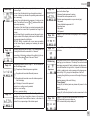
10. MENUS
EVOPLUS SMALL circulators offer a user menu accessible from the Home Page by
pressing and releasing the central “Menu” button.
Below are shown the user menu pages with which it is possible to check the system
status and modify its settings.
If the menu pages show a key at bottom left it means that it is not possible to change the
settings. To unblock the menus go to the Home Page and press the hidden button and
the button under the key at the same time until the key disappears.
If no button is pressed for 60 minutes, the settings are automatically blocked and
the display switches off. When any button is pressed the display lights up again
and the “Home Page” appears.
To navigate in the menus, press the central button.
To return to the previous page, hold down the hidden button, then press and release the
central button.
To modify the settings use the left and right buttons.
To conrm the change of a setting, hold down the central button “OK” for 3 seconds.
Conrmation will be indicated by the following icon:

ENGLISH
GB
12
Home Page
The main settings of the system are graphically summed up on
the Home Page.
The icon at top left indicates the type of regulation selected.
The icon at centre top indicates the operating mode selected
(auto or economy).
The icon at top right indicates the presence of a single or twin
inverter. The rotation of the icon or indicates which circu-
lation pump is operating.
At the centre of the Home Page is a read-only parameter which
can be chosen from a small set of parameters on Page 9.0 of
the menu.
From the Home Page it is possible to access the page for regu-
lating the contrast of the display: hold down the hidden button,
then press and release the right button.
EVOPLUS SMALL circulators offer a user menu accessible
from the Home Page by pressing and releasing the central
“Menu” button
.
Page 1.0
The factory settings are set from Page 1.0 by holding down the
left and right buttons at the same time for 3 seconds.
The resetting of the factory settings will be notied by the ap-
pearance of the symbol next to the word “Default”.
Page 2.0
The regulating mode is set from Page 2.0. You can choose be-
tween the following modes:
1 = Proportional differential pressure regulation.
2 = Regulation with constant differential pressure.
3 = Regulation with constant curve with rotation speed set
from the display.
Page 2.0 displays 3 icons which represent:
- central icon = setting currently selected;
- right icon = next setting;
- left icon = previous setting.
Page 3.0
The regulating set-point can be modied from Page 3.0.
Depending on the type of regulation chosen on the previous
page, the set-point to be set will be a head or, in the case of a
Constant Curve, a percentage of the rotation speed.
Page 9.0
On page 9.0 it is possible to choose the parameter to be dis-
played on the Home Page:
H: Measured head expressed in metres
Q: Estimated ow rate expressed in m3/h
S: Rotation speed expressed in revs per minute (rpm)
E: Not present
P: Power distributed expressed in W
h: Operating hours
T: Not present
T1: Not present
Page 10.0
On page 10.0 you can choose the language in which to display
the messages.
Page 11.0
On page 11.0 you can display the alarms log by pressing the
right button.
Alarms Log
If the system nds any faults it records them permanently in the
alarms log (up to a maximum of 15 alarms). For each recorded
alarm a page composed of 3 parts is displayed: an alphanumer-
ic code that identies the type of fault, a symbol that illustrates
the fault in graphic mode, and a message in the language se-
lected on Page 10.0, giving a brief description of the fault.
By pressing the right button you can scroll through all the pages
of the log.
2 questions appear at the end of the log:
1.“Reset Alarms?”
Pressing OK (left button) resets any alarms still present in the
system.
2.“Delete Alarms Log”
Pressing OK (left button) deletes the alarms memorised in the
log.
Page 13.0
On page 13.0 you can set the system status in ON or OFF.
If ON is selected the pump is always on.
If OFF is selected the pump is always off.

ENGLISH
GB
13
11. FACTORY SETTINGS
Parameter Value
Regulating mode = Proportional differential pressure
regulation
Twin operating mode = Alternate every 24h
Pump start control ON
12. TYPES OF ALARM
Alarm Code Alarm Symbol Alarm Description
e0 - e16; e21 Internal Error
e17 - e19 Short Circuit
e20 Voltage Error
e22 - e31 Internal Error
e32 - e35 Electronic system excess temperature
e37 Low voltage
e38 High voltage
e39 - e40 Pump blocked
e46 Pump Disconnected
e42 Dry operation
e56
Motor excess temperature (motor
protector trips)
e57
Frequency of PWM external signal less
than 100 Hz
e58
Frequency of PWM external signal
greater than 5 kHz
Table 1: Factory settings
Table 2: List of alarms
INFORMATION
Frequently asked questions (faq) on the ecodesign directive 2009/125/ec establishing a
framework for the setting of ecodesign requirements for energy-related products and its
implementing regulations:
http://ec.europa.eu/enterprise/policies/sustainable-business/documents/eco-de-
sign/guidance/les/20110429_faq_en.pdf
Guidelines accompanying commission regulations implementing the ecodesign directive:
http://ec.europa.eu/energy/efciency/ecodesign/legislation_en.htm - see “circula-
tors.
13. ERROR CONDITION AND RESET
Display
indication
Description Reset
e0 – e16 Internal error
- Switch off system power.
- Wait for the warning lights on the control
panel to go off, then power the system
again.
- If the error persists, change the circu-
lator.
e37
Low mains
voltage (LP)
- Switch off system power.
- Wait for the warning lights on the control
panel to go off, then power the system
again.
- Check that the mains voltage is correct,
if necessary reset it at the plate values.
e38
High mains
voltage (HP)
- Switch off system power.
- Wait for the warning lights on the control
panel to go off, then power the system
again.
- Check that the mains voltage is correct,
if necessary reset it at the plate values.
e32-e35
Critical over-
heating of
electronic parts
- Switch off system power.
- Wait for the warning lights on the control
panel to go off.
- Check that the system ventilation ducts
are not blocked and that the environ-
ment temperature of the premises is
correct.

ENGLISH
GB
14
e39-e40
Protection
against
overcurrent
- Check that the circulator turns freely.
- Check that any antifreeze added does
not exceed the maximum percentage
of 30%.
e21-e30 Voltage Error
- Switch off system power.
- Wait for the warning lights on the control
panel to go off, then power the system
again.
- Check that the mains voltage is correct,
if necessary reset it at the plate values.
e31
Twin
communication
absent
- Check that the twin communication ca-
ble is intact.
- Check that both circulators are pow-
ered.
e42 Dry operation - Put the system under pressure.
e56
Motor excess
temperature
- Switch off system power.
- Wait for the motor to cool down
- Power the system again
e57 ; e58
f < 100 Hz
f > 5 kHz
Check that the PWM external signal is
operating and connected as specied.
Energy Efciency Index - EEI
The benchmark for the most efcient circulators is EEI ≤ 0,20.

ESPAÑOL
ES
15
ÍNDICE
1. Advertencias particulares ......................................................................................16
2. Líquidos bombeados .............................................................................................16
3. Compatibilidad electromagnética (EMC) ..............................................................16
4. Gestión ....................................................................................................................16
4.1 Almacenaje .............................................................................................................16
4.2 Transporte ..............................................................................................................16
4.3 Peso .......................................................................................................................16
5. Instalación ...............................................................................................................16
5.1 Instalación y mantenimiento del circulador ............................................................. 16
5.2 Rotación de las cabezas del motor ........................................................................17
5.3 Válvula de retención ...............................................................................................17
6. Conexiones eléctricas ............................................................................................17
6.1 Conexión de alimentación ......................................................................................17
7. Puesta en marcha ...................................................................................................17
8. Funzioni ....................................................................................................................17
8.1 Modos de regulación ..............................................................................................17
8.1.1 Regulación de presión diferencial proporcional ................................................17
8.1.2 Regulación de presión diferencial constante ....................................................18
8.1.3 Regulación de curva constante ........................................................................18
8.2 Módulos de expansión ............................................................................................18
9. Panel de control ......................................................................................................18
9.1 Display gráco ........................................................................................................18
9.2 Teclas de desplazamiento ......................................................................................18
9.3 Luces de señalización ............................................................................................18
10. Menú ......................................................................................................................18
11. Configuraciones de fábrica .................................................................................20
12. Tipos de alarmas ..................................................................................................20
13. Condición de error y restablecimiento ...............................................................21
ÍNDICE DE LAS FIGURAS
Figura 1: Posición de montaje ....................................................................................... 1A
Figura 2: Instalación en tuberías horizontales ............................................................... 1A
Figura 3: Cableado del conector de alimentación ......................................................... 1A
Figura 4: Conexión del conector de alimentación ......................................................... 1A
Figura 5: Panel de control ............................................................................................. 1A
ÍNDICE DE LAS TABLAS
Tabla 1: Conguraciones de Fábrica ............................................................................20
Tabla 2: Listado de Alarmas .........................................................................................20
Table: Maximum head (Hmax) and maximum ow rate (Qmax) of EVOPLUS
SMALL circulators ....................................................................................................... 2A
Table: Energy Efciency Index - EEI ..........................................................................3A
Sidan laddas...
Sidan laddas...
Sidan laddas...
Sidan laddas...
Sidan laddas...
Sidan laddas...
Sidan laddas...
Sidan laddas...
Sidan laddas...
Sidan laddas...
Sidan laddas...
Sidan laddas...
Sidan laddas...
Sidan laddas...
Sidan laddas...
Sidan laddas...
Sidan laddas...
Sidan laddas...
Sidan laddas...
Sidan laddas...
Sidan laddas...
Sidan laddas...
Sidan laddas...
Sidan laddas...
Sidan laddas...
Sidan laddas...
Sidan laddas...
Sidan laddas...
Sidan laddas...
Sidan laddas...
Sidan laddas...
Sidan laddas...
Sidan laddas...
Sidan laddas...
Sidan laddas...
Sidan laddas...
Sidan laddas...
Sidan laddas...
Sidan laddas...
Sidan laddas...
Sidan laddas...
Sidan laddas...
Sidan laddas...
Sidan laddas...
Sidan laddas...
Sidan laddas...
Sidan laddas...
Sidan laddas...
Sidan laddas...
Sidan laddas...
Sidan laddas...
Sidan laddas...
Sidan laddas...
Sidan laddas...
Sidan laddas...
Sidan laddas...
Sidan laddas...
Sidan laddas...
Sidan laddas...
Sidan laddas...
Sidan laddas...
Sidan laddas...
Sidan laddas...
Sidan laddas...
Sidan laddas...
Sidan laddas...
Sidan laddas...
Sidan laddas...
Sidan laddas...
Sidan laddas...
Sidan laddas...
Sidan laddas...
Sidan laddas...
Sidan laddas...
Sidan laddas...
Sidan laddas...
Sidan laddas...
Sidan laddas...
Sidan laddas...
Sidan laddas...
Sidan laddas...
Sidan laddas...
Sidan laddas...
Sidan laddas...
Sidan laddas...
Sidan laddas...
Sidan laddas...
Sidan laddas...
Sidan laddas...
Sidan laddas...
Sidan laddas...
Sidan laddas...
Sidan laddas...
Sidan laddas...
Sidan laddas...
Sidan laddas...
Sidan laddas...
Sidan laddas...
Sidan laddas...
Sidan laddas...
Sidan laddas...
Sidan laddas...
Sidan laddas...
Sidan laddas...
Sidan laddas...
Sidan laddas...
Sidan laddas...
Sidan laddas...
Sidan laddas...
Sidan laddas...
Sidan laddas...
Sidan laddas...
Sidan laddas...
Sidan laddas...
Sidan laddas...
Sidan laddas...
Sidan laddas...
Sidan laddas...
Sidan laddas...
Sidan laddas...
Sidan laddas...
Sidan laddas...
Sidan laddas...
Sidan laddas...
Sidan laddas...
Sidan laddas...
Sidan laddas...
Sidan laddas...
Sidan laddas...
Sidan laddas...
Sidan laddas...
Sidan laddas...
Sidan laddas...
Sidan laddas...
Sidan laddas...
Sidan laddas...
-
 1
1
-
 2
2
-
 3
3
-
 4
4
-
 5
5
-
 6
6
-
 7
7
-
 8
8
-
 9
9
-
 10
10
-
 11
11
-
 12
12
-
 13
13
-
 14
14
-
 15
15
-
 16
16
-
 17
17
-
 18
18
-
 19
19
-
 20
20
-
 21
21
-
 22
22
-
 23
23
-
 24
24
-
 25
25
-
 26
26
-
 27
27
-
 28
28
-
 29
29
-
 30
30
-
 31
31
-
 32
32
-
 33
33
-
 34
34
-
 35
35
-
 36
36
-
 37
37
-
 38
38
-
 39
39
-
 40
40
-
 41
41
-
 42
42
-
 43
43
-
 44
44
-
 45
45
-
 46
46
-
 47
47
-
 48
48
-
 49
49
-
 50
50
-
 51
51
-
 52
52
-
 53
53
-
 54
54
-
 55
55
-
 56
56
-
 57
57
-
 58
58
-
 59
59
-
 60
60
-
 61
61
-
 62
62
-
 63
63
-
 64
64
-
 65
65
-
 66
66
-
 67
67
-
 68
68
-
 69
69
-
 70
70
-
 71
71
-
 72
72
-
 73
73
-
 74
74
-
 75
75
-
 76
76
-
 77
77
-
 78
78
-
 79
79
-
 80
80
-
 81
81
-
 82
82
-
 83
83
-
 84
84
-
 85
85
-
 86
86
-
 87
87
-
 88
88
-
 89
89
-
 90
90
-
 91
91
-
 92
92
-
 93
93
-
 94
94
-
 95
95
-
 96
96
-
 97
97
-
 98
98
-
 99
99
-
 100
100
-
 101
101
-
 102
102
-
 103
103
-
 104
104
-
 105
105
-
 106
106
-
 107
107
-
 108
108
-
 109
109
-
 110
110
-
 111
111
-
 112
112
-
 113
113
-
 114
114
-
 115
115
-
 116
116
-
 117
117
-
 118
118
-
 119
119
-
 120
120
-
 121
121
-
 122
122
-
 123
123
-
 124
124
-
 125
125
-
 126
126
-
 127
127
-
 128
128
-
 129
129
-
 130
130
-
 131
131
-
 132
132
-
 133
133
-
 134
134
-
 135
135
-
 136
136
-
 137
137
-
 138
138
-
 139
139
-
 140
140
-
 141
141
-
 142
142
-
 143
143
-
 144
144
-
 145
145
-
 146
146
-
 147
147
-
 148
148
-
 149
149
-
 150
150
-
 151
151
-
 152
152
-
 153
153
-
 154
154
-
 155
155
-
 156
156


DAB EVOPLUS SMALL B 80/250.40 M Instruction For Installation And Maintenance
- Typ
- Instruction For Installation And Maintenance
på andra språk
- italiano: DAB EVOPLUS SMALL B 80/250.40 M
- čeština: DAB EVOPLUS SMALL B 80/250.40 M
- slovenčina: DAB EVOPLUS SMALL B 80/250.40 M
- español: DAB EVOPLUS SMALL B 80/250.40 M
- Deutsch: DAB EVOPLUS SMALL B 80/250.40 M
- polski: DAB EVOPLUS SMALL B 80/250.40 M
- português: DAB EVOPLUS SMALL B 80/250.40 M
- français: DAB EVOPLUS SMALL B 80/250.40 M
- Türkçe: DAB EVOPLUS SMALL B 80/250.40 M
- English: DAB EVOPLUS SMALL B 80/250.40 M
- русский: DAB EVOPLUS SMALL B 80/250.40 M
- suomi: DAB EVOPLUS SMALL B 80/250.40 M
- Nederlands: DAB EVOPLUS SMALL B 80/250.40 M
- română: DAB EVOPLUS SMALL B 80/250.40 M
Relaterade papper
Andra dokument
-
Grundfos UPE Series 2000 Installation And Operating Instructions Manual
-
ESBE GRA311 Series Användarmanual
-
Carrier 30AWH006HB Installationsguide
-
Grundfos MAGNA 32-100 N Installation And Operating Instructions Manual
-
Waterco Lacronite Eco V Pump Användarmanual
-
-
Vornado 683DC Bruksanvisning
-
Hendi 222638 Användarmanual
-
 Thermo Fisher Scientific Horizon AC-FTS Fogging Test Unit Användarmanual
-
 Thermo Fisher Scientific Horizon PC-FTS Fogging Test Unit Användarmanual

