ABB GH Q630 7043 P0001 Mounting And Operating Instructions
- Typ
- Mounting And Operating Instructions

Montage- und Betriebsanleitung
ABB i-bus쏐 EIB
Spannungsversorgung 320 mA
mit Drossel
Typ SV/S 30.320.5
Bed.-Anl. Nr. GH Q630 7043 P0001
D
ABB STOTZ-KONTAKT GmbH
Postfach 101 680, D-69006 Heidelberg
Telefon (06221) 701-434, Telefax (06221) 701-690

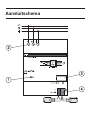
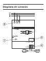
Anschlußbild

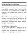
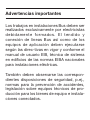
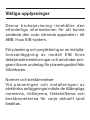
Wichtige Hinweise
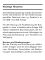
Diese Betriebsanleitung enthält die erforder-
lichen Informationen für den bestimmungs-
gemäßen Gebrauch des o.g. Gerätes in ei-
ner ABB i-bus EIB Anlage.
Für die Planung und Projektierung der Bus-
geräte in einer Installationsbus-Anlage EIB
stehen detaillierte Beschreibungen der An-
wendungsprogramme sowie Unterlagen zur
Planungsunterstützung vom Hersteller zur
Verfügung.
Normen und Bestimmungen
Bei der Planung und Errichtung von elektri-
schen Anlagen sind die einschlägigen Nor-
men, Richtlinien, Vorschriften und Bestim-
mungen des jeweiligen Landes zu beachten.

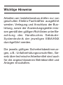
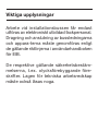
Wichtige Hinweise
Arbeiten am Installationsbus dürfen nur von
geschulten Elektro-Fachkräften ausgeführt
werden. Verlegung und Anschluss der Bus-
leitung, sowie der Anwendungsgeräte müs-
sen gemäß den gültigen Richtlinien unter Be-
achtung des Handbuches Gebäude-
Systemtechnik der jeweiligen EIBA/KNX
durchgeführt werden.
Die jeweils gültigen Sicherheitsbestimmun-
gen, z.B.: Unfallverhütungsvorschriften, Ge-
setz über technische Arbeitsmittel sind auch
für die angeschlossenen Betriebsmittel und
Anlagen einzuhalten.

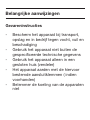
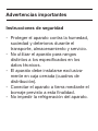
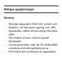
Wichtige Hinweise
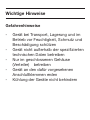
Gefahrenhinweise
- Gerät bei Transport, Lagerung und im
Betrieb vor Feuchtigkeit, Schmutz und
Beschädigung schützen
- Gerät nicht außerhalb der spezifizierten
technischen Daten betreiben
- Nur im geschlossenen Gehäuse
(Verteiler) betreiben
- Gerät an den dafür vorgesehenen
Anschlußklemmen erden
- Kühlung der Geräte nicht behindern

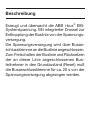
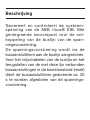
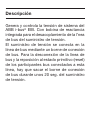
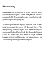
Beschreibung
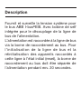
Erzeugt und überwacht die ABB i-bus
®
EIB-
Systemspannung. Mit integrierter Drossel zur
Entkopplung der Buslinie von der Spannungs-
versorgung.
Die Spannungsversorgung wird über Busan-
schlussklemme an die Buslinie angeschlossen.
Zum Freischalten der Buslinie und Rücksetzen
der an dieser Linie angeschlossenen Bus-
teilnehmer in den Grundzustand (Reset) muß
die Busanschlussklemme für ca. 20 s von der
Spannungsversorgung abgezogen werden.

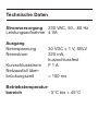
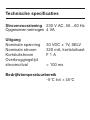
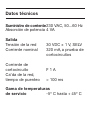
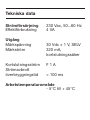
Technische Daten
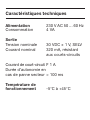
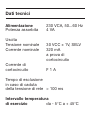
Stromversorgung 230 VAC, 50…60 Hz
Leistungsaufnahme 4 VA
Ausgang
Nennspannung 30 VDC ± 1 V, SELV
Nennstrom 320 mA,
kurzschlussfest
Kurzschlussstrom ) 1 A
Netzausfall über-
brückungszeit > 100 ms
Betriebstemperatur-
bereich - 5°C bis + 45°C

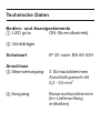
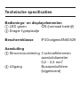
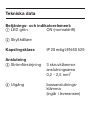
Technische Daten
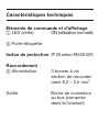
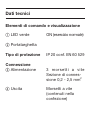
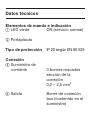
Bedien- und Anzeigeelemente
LED grün ON (Normalbetrieb)
Schildträger
Schutzart IP 20 nach EN 60 529
Anschluss
Stromversorgung 3 Schraubklemmen
Anschlußquerschnitt
0,2 - 2,5 mm
2
Ausgang Busanschlussklemme
(im Lieferumfang
enthalten)

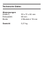
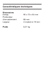
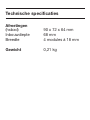
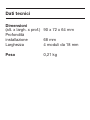
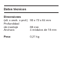
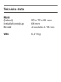
Abmessungen
(HxBxT) 90 x 72 x 64 mm
Einbautiefe 68 mm
Breite 4 Module à 18 mm
Gewicht 0,21 kg
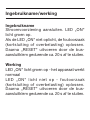
Technische Daten

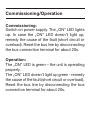
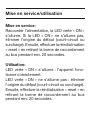
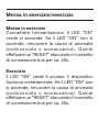
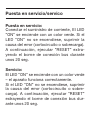
Inbetriebnahme/Betrieb
Inbetriebnahme:
Stromversorgung anschließen,
LED „ON“ leuchtet grün auf.
Falls die LED „ON“ nicht aufleuchtet, Fehler-
ursache (Kurzschluß oder Überlastung) be-
seitigen. Danach „RESET“ durch Abziehen
der Busanschlußklemme für ca. 20s durch-
führen.
Betrieb:
LED „ON“ leuchtet grün – das Gerät funktio-
niert ordnungsgemäß.
LED „ON“ leuchtet nicht – Fehlerursache
(Kurzschluß oder Überlastung) beseitigen.
Danach „RESET“ durch Abziehen der Bus-
anschlußklemme für ca. 20s durchführen.

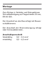
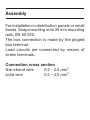
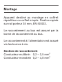
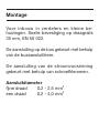
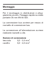
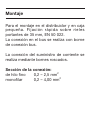
Montage
Zum Einbau in Verteiler und Kleingehäuse.
Schnellbefestigung auf Tragschienen 35 mm,
EN 50 022.
Der Anschluß an den Bus erfolgt mit Busan-
schlußklemme.
Der Anschluß der Stromversorgung erfolgt
über Schraubklemmen.
Anschlußquerschnitt
feindrähtig 0,2 - 2,5 mm
2
eindrähtig 0,2 - 4,0 mm
2


GB
ABB STOTZ-KONTAKT GmbH
Postfach 101 680, D-69006 Heidelberg
Phone (06221) 701-434, Fax (06221) 701-690
Mounting and Operating Instructions
ABB i-bus쏐 EIB
Power supply 320 mA
with choke
Type SV/S 30.320.5
Instr.-no.: GH Q630 7043 P0001

Connection diagram

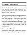
Important notes
These operating instructions contain the
necessary information for the correct use of
the aforementioned unit in an ABB i-bus EIB
system.
Detailed descriptions of the user programs
and documentation on planning support by
the manufacturer are available for planning
and configuring the bus units in an ABB i-
bus EIB system.
Standards and regulations
The relevant standards, guidelines, speci-
fications and regulations of the country in
question must be observed for planning and
setting up electrical systems.

Important notes
Work on the installation bus may only be
carried out by trained electricians. The bus
line and the units must be installed and
connected in accordance with the relevant
guidelines, observing the EIB user manual
Building Systems Engineering of the natio-
nal EIBA.
The relevant safety regulations, e.g. accident
prevention regulations, law on technical work
equipment, must also be observed for the
connected equipment and systems.

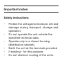
Important notes
Safety instructions
- Protect the unit against moisture, dirt and
damage during transport, storage and
operation.
- Do not operate the unit outside the
specified technical data.
- Operate only in a closed housing
(distribution cabinet).
- Earth the unit at the terminals provided
- if existing - for this purpose.
- Do not obstruct cooling of the units.

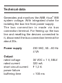
Technical data
Generates and monitors the ABB i-bus
®
EIB
system voltage. With integrated choke for
isolating the bus line from power supply.
The bus connection is made via bus
connection terminal. For freeing up the bus
line and resetting the devices connected to
it, disconnect the bus connection terminal for
about 20s.
Power supply 230 VAC, 50…60 Hz
4 VA
Output
rated voltage 30 VDC ± 1 V, SELV
rated current 320 mA
short circuit current ) 1,2 A
power failure
buffering time > 100 ms

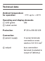
Technical data
Ambient temperature
for operation - 5° C up to + 45°C
Operating and display elements
LED green ON
Label carrier
Protection IP 20 to EN 60 529
Connection
power supply 3 screw terminals
connection cross
section: 0.2-2.5 mm
2
output bus connection
terminal (included in
scope of delivery)

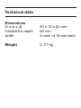
Technical data
Dimensions
(h x w x d) 90 x 72 x 64 mm
Installation depth 68 mm
width 4 mod. of 18 mm each
Weight 0. 21 kg
Sidan laddas...
Sidan laddas...
Sidan laddas...
Sidan laddas...
Sidan laddas...
Sidan laddas...
Sidan laddas...
Sidan laddas...
Sidan laddas...
Sidan laddas...
Sidan laddas...
Sidan laddas...
Sidan laddas...
Sidan laddas...
Sidan laddas...
Sidan laddas...
Sidan laddas...
Sidan laddas...
Sidan laddas...
Sidan laddas...
Sidan laddas...
Sidan laddas...
Sidan laddas...
Sidan laddas...
Sidan laddas...
Sidan laddas...
Sidan laddas...
Sidan laddas...
Sidan laddas...
Sidan laddas...
Sidan laddas...
Sidan laddas...
Sidan laddas...
Sidan laddas...
Sidan laddas...
Sidan laddas...
Sidan laddas...
Sidan laddas...
Sidan laddas...
Sidan laddas...
Sidan laddas...
Sidan laddas...
Sidan laddas...
Sidan laddas...
Sidan laddas...
Sidan laddas...
Sidan laddas...
Sidan laddas...
Sidan laddas...
Sidan laddas...
Sidan laddas...
Sidan laddas...
Sidan laddas...
Sidan laddas...
Sidan laddas...
Sidan laddas...
Sidan laddas...
Sidan laddas...
Sidan laddas...
Sidan laddas...
Sidan laddas...
Sidan laddas...
Sidan laddas...
Sidan laddas...
Sidan laddas...
Sidan laddas...
Sidan laddas...
Sidan laddas...
Sidan laddas...
Sidan laddas...
Sidan laddas...
Sidan laddas...
Sidan laddas...
Sidan laddas...
Sidan laddas...
Sidan laddas...
-
 1
1
-
 2
2
-
 3
3
-
 4
4
-
 5
5
-
 6
6
-
 7
7
-
 8
8
-
 9
9
-
 10
10
-
 11
11
-
 12
12
-
 13
13
-
 14
14
-
 15
15
-
 16
16
-
 17
17
-
 18
18
-
 19
19
-
 20
20
-
 21
21
-
 22
22
-
 23
23
-
 24
24
-
 25
25
-
 26
26
-
 27
27
-
 28
28
-
 29
29
-
 30
30
-
 31
31
-
 32
32
-
 33
33
-
 34
34
-
 35
35
-
 36
36
-
 37
37
-
 38
38
-
 39
39
-
 40
40
-
 41
41
-
 42
42
-
 43
43
-
 44
44
-
 45
45
-
 46
46
-
 47
47
-
 48
48
-
 49
49
-
 50
50
-
 51
51
-
 52
52
-
 53
53
-
 54
54
-
 55
55
-
 56
56
-
 57
57
-
 58
58
-
 59
59
-
 60
60
-
 61
61
-
 62
62
-
 63
63
-
 64
64
-
 65
65
-
 66
66
-
 67
67
-
 68
68
-
 69
69
-
 70
70
-
 71
71
-
 72
72
-
 73
73
-
 74
74
-
 75
75
-
 76
76
-
 77
77
-
 78
78
-
 79
79
-
 80
80
-
 81
81
-
 82
82
-
 83
83
-
 84
84
-
 85
85
-
 86
86
-
 87
87
-
 88
88
-
 89
89
-
 90
90
-
 91
91
-
 92
92
-
 93
93
-
 94
94
-
 95
95
-
 96
96


ABB GH Q630 7043 P0001 Mounting And Operating Instructions
- Typ
- Mounting And Operating Instructions
på andra språk
- italiano: ABB GH Q630 7043 P0001
- español: ABB GH Q630 7043 P0001
- Deutsch: ABB GH Q630 7043 P0001
- français: ABB GH Q630 7043 P0001
- English: ABB GH Q630 7043 P0001
- Nederlands: ABB GH Q630 7043 P0001