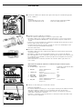
Minebea Intec CAPXS.. Models Stainless Steel Weighing Platforms for Use in Hazardous Areas/Locations Bruksanvisning
- Kategori
- Personliga skalor
- Typ
- Bruksanvisning

98648-010-96
98648-010-96
Combics CAPXS...

2
Contents
2 Symbols
2 Intended Use
3 Warning and Safety Information
3 Warranty
4 Installation Instructions
6 Installation
9 Care and Maintenance
The following symbols are used in these instructions:
§indicates required steps
$indicates steps required only under certain conditions
> describes what happens after you have performed
a certain step
– indicates an item in a list
!indicates a hazard
Make sure you observe the following warning and safety
information in its entirety during installation and operation,
as well as while performing maintenance and repair work on
the equipment. It is important that all personnel using the
Combics equipment understand this information, and have
access to it at all times.
Furthermore, the warning and safety information supplied
with any electrical equipment connected, such as the indica-
tor, must be observed as well. The warning and safety infor-
mation can be supplemented by the equipment operator.
Make sure all operating personnel are informed of any addi-
tions to these instructions.
Intended Use
The weighing platform and the connected indicator
are intended exclusively for use in weighing.
English page 2
In cases involving questions
of interpretation, the German-language
version shall prevail.
Deutsch Seite 10
Im Auslegungsfall ist die
deutsche Sprache maßgeblich.
Français page 18
En cas de questions concernant
l’interprétation, la version
en langue allemande fera autorité.
Italiano página 26
In caso di interpretazione,
fa testo la versione
in lingua tedesca.
Español página 34
En caso de interpretación,
la versión en lengua alemana
será determinante.
Nederlands pagina 42
Português página 50
Svenska sida 58
Suomi sivu 66
Dansk side 74
Ελληνικ Σελδα 82

3
Warning and Safety Information
The weighing platform meets the
requirements for Group II, Category 2
equipment in accordance with EC
Directive 94/9/EC and bears the desig-
nation hII 2 GD EEx ib IIC T4...T6
T135...155°C in accordance with KEMA
EC type-examination certificate
02ATEX1010X.
Furthermore, the weighing platform
meets the EC Directives for electromag-
netic compatibility (see the Declaration
of Conformity). Improper use or
handling, however, can result in dam-
age and/or injury.
– The weighing platform can be operated
indoors or outdoors. This weighing
platform may not be used in the med-
ical industry (as a medicinal product).
– The weighing platform may be used in
Zone 1, 2, 21 or 22 hazardous areas or
Class 1, Division 1 or 2 hazardous loca-
tions (gas and dust explosion hazards).
Please make sure the currently valid
regulations and guidelines for installing
equipment in the hazardous areas/loca-
tions listed above (e.g., EN60079-14
or, in Germany, ElexV) are strictly
observed. Whether the equipment can
be used in a given area containing
potentially explosive agents must be
checked on a case-by-case basis.
– The weighing platform may be used
and operated by qualified personnel
only. The permitted uses of the weigh-
ing platform are specified in the type-
examination certificate.
– Do not expose the weighing platform
to aggressive chemical vapors or to
extreme temperatures, moisture, shocks,
or vibration. The permissible operating
temperature range during operation is
–10°C to 40°C (14°F to 104°F).
– If you use suction lifting equipment to
lift the load plate, always wear gloves,
hard-toed safety boots and protective
clothing. Warning: Danger of personal
injury! Only reliable personnel who are
qualified to perform such work are
allowed to use suction lifting equip-
ment.
– Suspension points are designated on
models of 1000 +1000 mm and larger.
If you need to transport or lift the
scale or load plate using a crane, do not
stand underneath the suspended scale
or load plate.
– Make sure to observe the applicable
safety rules and regulations for the pre-
vention of accidents.
– Do not damage the junction box or the
load cells during transport.
– Installation in a Zone 1, 2, 21 or 22
hazardous area or Class 1, Division 1 or
2 hazardous location must be per-
formed by a trained technician who is
familiar with the assembly and opera-
tion of the equipment, as well as with
the procedure for putting the system
into operation. Furthermore, the
trained technician must have the
required qualifications and must be
familiar with the relevant guidelines
and regulations. If you need assistance,
contact your dealer or the
Mebea Intec Service Center. Any installa-
tion work that does not conform to the
instructions in this manual will result
in forfeiture of all claims under the
manufacturer’s warranty. Be sure to
observe all restrictions listed in the
type-examination certificate. Operating
the weighing platform beyond the
limits imposed by these restrictions is
not permitted, and constitutes use
of the equipment for other than its
intended purpose.
– Have the equipment inspected at
appropriate intervals for correct
functioning and safety by a trained
technician.
– The junction box may be opened only
by authorized service technicians who
have been trained by Minebea Intec and
who follow Minebea Intec’ standard operat-
ing procedures for maintenance and
repair work.
– Always make sure the weighing plat-
form is disconnected from AC power
before performing any installation,
cleaning, maintenance or repair work.
If the equipment housing is opened by
anyone other than persons authorized
by Minebea Intec, all claims under the
manufacturer’s warranty are forfeited. Use
only original Minebea Intec spare parts.
– Handle the equipment as specified in
EN 60529 (in Germany: VDE 0470
Part 1) in accordance with its protection
(IP) rating. The protection rating of
the weighing platform is IP67. Do not
damage the IP protection when clean-
ing the equipment. The IP protection
rating is ensured only if the rubber
gasket is installed on the junction box
and all cable gland screw fasteners are
connected securely. Any installation
work that does not conform to the
instructions in this manual will result
in forfeiture of all claims under the
manufacturer’s warranty.
– If you use cables purchased from
another manufacturer, check the pin
assignments before connecting the
cable to Minebea Intec equipment. Check the
assignments in the cable against those
specified by Minebea Intec and disconnect
any wires that are assigned differently.
The operator shall be solely responsible
for any damage or injuries that occur
when using cables not supplied
by Minebea Intec.
– When using the weighing platform in
hazardous areas/locations, make sure
there is no current or voltage in the
equipment before connecting or dis-
connecting current-carrying cables to or
from the platform. Disconnect the
platform from AC power before con-
necting or disconnecting cables.
– Avoid exposing the weighing platform
to static electricity; be sure to connect
the equipotential bonding conductor to
the junction box.
– Disconnecting equipotential bonding
conductors is not permitted.
– If you see any indication that the
weighing platform cannot be operated
safely (for example, due to damage),
turn off the platform and lock it in a
secure place so that it cannot be used
for the time being. Observe the rele-
vant safety precautions and inform per-
sonnel as required.
– The casing on all connecting cables, as
well as the casing on wires inside the
equipment housing, is made of PVC.
Chemicals that corrode these materials
must be kept away from these cables.
– Make sure the weighing instrument is
not exposed to substances that release
chlorine ions at the place of use. If
such exposure cannot be ruled out, the
operator is responsible for establishing
and observing appropriate safety pre-
cautions, to be checked at regular inter-
vals for continued effectiveness.
– The load cells installed are manufac-
tured by Global Weighing Technologies;
type designations: 011299/... through
011311/...; EC type-examination
certificate no. PTB 02 ATEX 2061.
The designation code is:
hII 2 G EEx ia IIC T4/T6.
The specifications are listed in the EC
type-examination certificate. The load
cell may be used and operated by quali-
fied personnel only. The permissible
use of the equipment is defined by the
equipment specifications and the rele-
vant safety regulations. Operating the
load cell beyond the specifications list-
ed in the type-approval certificate is not
permitted, and constitutes use of the
equipment for other than its intended
purpose. All restrictions listed in the
type-examination certificate must be
strictly observed.
Warranty
Do not miss out on the benefits of our
full warranty. Please contact your local
Minebea Intec office or dealer for further
information. If available, complete the
warranty registration card, indicating
the date of installation, and return the
card to your Minebea Intec office or dealer.

44
Installation Instructions
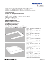
§Prepare a suitable place of installation for the weighing platform. The place of installa-
tion should be dry, level and even. The allowable operating temperature range is
–10°C to +40° (14°F to 104°F). The permissible load that can be carried by the chosen
working surface must be sufficient for both the weighing platform and any load
placed on the platform.
If you need to use the weighing platform in areas exposed to heavy traffic (e.g., forklift
trucks), you should install a protective frame, consisting of angular braces, around the
weighing platform.
Do not expose the weighing platform unnecessarily to extreme temperatures, moisture,
shocks, or vibration that could result in damage.
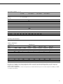
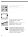
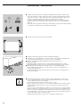
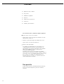
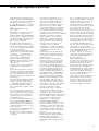
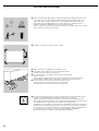
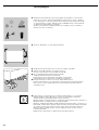
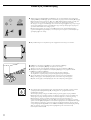
§The air bubble must be centered within the circle on the level indicator.
§Level the weighing platform using the leveling feet as described below:
§Check to ensure that all leveling feet rest securely on the work surface.
> Each of the leveling feet must support an equal load.
§Loosen the lock nuts on the leveling feet using a 19-mm open-end wrench (spanner).
> Adjusting the leveling feet:
To raise the weighing platform, extend the leveling feet (turn clockwise).
To lower the weighing platform, retract the leveling feet (turn counterclockwise).
§After leveling the weighing platform, retighten the lock nuts securely as described below:
Low-capacity platforms (1 load cell): tighten the lockouts against the platform frame;
high-capacity platforms (4 load cells): tighten the lock nuts against the platform feet.
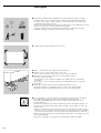
§If the weighing platform is in a hazardous area/location, it must be grounded (i.e., an
equipotential bonding conductor must be connected). This connection should be made
by a trained technician.
All Combics weighing platforms are equipped with a connector for the grounding
conductor.
This is located either below the load pan, on the junction box, or on the lower frame of
the weighing platform. The position is marked in each case by the symbol shown here,
indicating the grounding (earthing) connection.
The grounding conductor is connected to a threaded bolt or terminal screw, or a bore
hole is provided. If a bore hole is provided, use a stainless steel screw and nut to connect
the grounding conductor. Use of a tooth lock washer is recommended, to prevent the
screw from coming loose. The wire used for the grounding conductor should have a
cross-sectional diameter of at least 4 mm2, with a suitable ring lug attached.
Connect all equipment, including peripheral devices, to the equipotential bonding
conductor.

5
Conditions for Installation
Before putting the equipment into operation, it is important to make sure that the cable
of the power supply is correctly connected to the power outlet (mains supply). All
equipment must be connected to the equipotential bonding conductor via grounding
cable (not included in delivery) connected to the grounding terminals on each device.
The dimensions of the grounding cable are specified in national regulations for electrical
installations. Installation must be performed by a trained technician in accordance with
national regulations and generally acknowledged rules of engineering.
Use only cabling and extensions approved by Minebea Intec, as these are made in accordance
with the restrictions on permissible cable lengths imposed by both the capacitance and
inductivity values (see the “Annex to EC Type-Examination Certificate” in the operating
instructions) and the requirements for electromagnetic compatibility.
Before putting the weighing system into operation for the first time, make sure there is
no hazard of explosion present at the place of installation. If there is any indication
that the equipment does not function properly (e.g., display remains blank, or no display
backlighting) due to damage during transport, disconnect the equipment from power
and notify your nearest Minebea Intec Service Center.
The weighing platform specifications for Ui, Li, Pi, Ta, temperature class, Ci, and Li are
listed in the EC type-examination certificate. This certificate also specifies the indicator
models that can be used with these platforms. These specifications must be observed
when connecting an indicator to the platform. Ci and Li values apply to weighing plat-
forms with a 3-m cable for connecting the indicator. (See also the “Certificate
of Proof of Intrinsic Safety” in the appendix to this manual.)
The explosion-protected weighing system must be installed in accordance with acknowl-
edged rules of engineering. These include national and international laws and regula-
tions, such as EN 60079-14 and EN 5281-1-2, for example. In particular, the conditions
described under Item 17 of the KEMA EC type-examination certificate, “Special
Conditions for Safe Use”, must be observed. Furthermore, national regulations for acci-
dent prevention and environmental protection must be observed at all times.
Before the platform is operated in a hazardous area/location, it must be inspected either
by a certified electrician or under the guidance and supervision of a certified electrician
to make sure that the weighing system complies with the applicable regulations (in
Germany, Section 12 of the ElexV). Determine whether the installation must be regis-
tered with technical inspection authorities (such as the trade board) in your country.
Regular inspections must also be performed on the system during operation. The system
should be inspected at intervals short enough to permit the prevention or early detection
of defects that arise as a result of normal wear and tear. The longest permissible interval
period is 3 years. Other conditions and standards that regulate the installation and
operation of the equipment and are applicable in your country must be met as well.
When performing inspections, generally acknowledged rules of engineering relevant to
these conditions must also be applied.
If the terminal housing is opened by anyone other than persons authorized by Minebea Intec,
or if the terminal is installed or operated incorrectly, this will result in forfeiture of
the approval for use in the stated hazardous area(s)/location(s) and of all claims under
the manufacturer’s warranty.

6
Installation
§Connect the cable of the weighing platform to a suitable indicator, such as the FCT01-X
from Minebea Intec.
Note:
The cable gland on Minebea Intec indicators is installed at the factory. Please use extreme
caution when performing any work on the equipment that affects this cable gland.
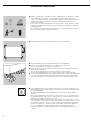
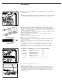
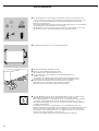
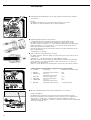
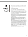
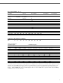
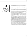
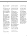
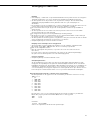
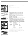
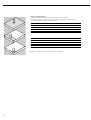
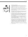
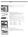
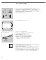
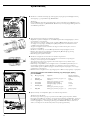
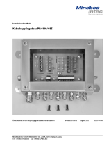
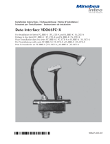
§Remove the casing from a length of the cable end and install the cable as follows:
– Remove the screw fastener from the cable gland and slide it over the end of the cable.
– Remove the casing from a section of the cable end (see illustration). The shielding (1)
must have contact with the clamps (2). Fold back 3 to 4 mm of the shielding so that it
overlaps the O-ring (see illustration).
– Expose approximately 15 cm (4 inches) of the wires (3) for connection within the terminal.
– Thread the cable through the cable gland.
– Make sure the shielding is in contact with the clamps. The shielding supplies the
grounding connection.
– Replace the screw fastener and tighten it securely.
§Connect the wire ends to the terminal strip:
– Remove the casing from a section of the cable end. Expose enough of the wires in the
cable for installation.
– Remove the casing from approx. 1 cm (0.5 in.) of the wires and affix ferrules to the
wire ends.
– Slide the enclosed protective sleeve over all the wires down to the cable gland, so that
no more than 5 cm of the wires is exposed between the end of the sleeve and the
terminal strip.
– Attach the wires securely to the screw terminals (blue = positive, brown or black =
negative)
Color Codes in the Weighing Platform Connecting Cable, Model CAPXS..
No. Signal des. Meaning Color of wire casing
1 BR_POS Bridge supply voltage (+) blue
2 SENSE_POS Sense (+) green
Bridge supply voltage
3 OUT_POS Measuring voltage positive white
4 OUT_NEG Measuring voltage (–) red
5 SENSE_NEG Sense (–) gray
Bridge supply voltage
6 BR_NEG Bridge supply voltage (–) black or brown
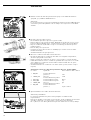
§Use a screwdriver to tighten the terminal screws.
Note on connecting the FCT01-X:
The bridge supply voltages are protected by 62mA fuses. To prevent the fuses from
reacting if wires are incorrectly connected, resistors between pin 1 and pin 6, between
pin 1 and the housing and between pin 6 and the housing must measure greater
than 140 ohms. Low-ohm connections are also required between pins 1 and 2 and
between pins 5 and 6.

7
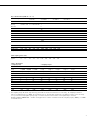
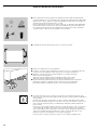
Key to Model Codes (CAPX ab - cd - e):
Product family Material Number of Capacity in kg Dimensions Resolution
load cells see Table 2 see Table 1 see Table 2
CAPX.. a b c d e
Combics S = 1 = one load cell
Analog stainless steel 4 = four load cells 3
Platform 6
15
30
60
150
300
600
1500
3000
Table 1: Model-specific data: Dimensions
Designation DC ED FE GF IG LL NL RN RR WR
Width (mm) 240 300 400 500 600 1000 1000 1250 1500 1500
Length (mm) 320 400 500 650 800 1000 1250 1500 1500 2000
Cable lengths (power cord)
Length (m),
approx. 1.5 1.5 3.0 3.0 3.0 6.0 6.0 6.0 6.0 6.0
Table 2: Resolutions:
1 weighing range 2 weighing ranges*
-L -I -LCE -NCE 2 +3000e
Weighing Weighing Weighing Resolution Weighing Resolution
range 15,000d 30,000d 1+3000e range range 1 range 1 range 2 range 2
in kg in g in g in g in kg in kg in g in kg in g
3 0.2 0.1 1 3 1.5 0.5 3 1
6 0.50.22 63162
15 1 0.5 5 15 6 2 15 5
30 2 1 10 30 15 5 30 10
60 5220 6030106020
150 10 5 50 150 60 20 150 50
300 20 10 100 300 150 50 300 100
600 50 20 200 600 300 100 600 200
1500 100 50 500 1500 600 200 1500 500
3000 200 100 1000 3000 1500 500 3000 1000
* The weighing ranges allowed in legal metrology in the EU are listed in the Declaration of Conformity. On weighing instruments
with two weighing ranges (2 +3000e), the instrument does not automatically switch back to the higher resolution of the fine range
once you use the second, higher-capacity range. In other words, the lower resolution of the higher range is retained.
Example: CAPXS4-3000WR-NCE = Combics analog platform in stainless steel with 4 load cells, weighing capacity 3000 kg, 2 +3000e
in verifiable version.

8
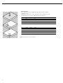
Operating Limits
Do not place loads on the weighing platform that exceed its maximum
weighing capacity.
Depending on the position of the load (center, side, one-sided corner load),
the maximum capacity of the weighing platform is as follows:
Model Center Side Corner
DC 50 35 20
ED 130 85 45
FE 300 200 100
GF 450 300 150
IG 900 600 300
LL 4500 3000 1500
NL 4500 3000 1500
RN 4500 3000 1500
RR 4500 3000 1500
WR 4500 3000 1500
!Please follow the safety instructions!

9
Care and Maintenance
Cleaning
$Unplug the weighing instrument from the AC power before cleaning.
Remove dust from the weighing platform regularly (see EC type-examination certificate)
$If the weighing instrument is in a dry room, use a damp cloth to wipe down the weighing plat-
form. You can use common household cleaning agents. Follow the manufacturer’s instructions
for the cleaning agent.
$The leveling feet are covered with rubber buffers. In hazardous areas/locations, these must be
cleaned using only a damp cloth. This prevents build-up of static electricity.
!Never use concentrated acids, bases, solvents or pure alcohol to clean the weighing platform.
$To clean the weighing platform in a wet area, wash it down using a gentle stream of water (60°C
max.) sprayed over the top of the load plate.
!Do not use high-pressure cleaning equipment to clean the weighing platform.
> If the water that you use to clean the weighing platform is too hot or too cold, the difference in
temperature between the water and the weighing platform can cause condensation within the
weighing platform. This condensation may cause the weighing platform to malfunction.
$If the scale is installed in a pit, make sure that no debris builds up in the crevices between the pit
and the platform, to prevent weighing errors.
$Regularly remove debris from the bottom of the pit.
Cleaning the Inside of the Weighing Platform
$To clean the inside of the weighing platform, remove the load plate.
Be especially careful when removing the load plate from scales of 1000 x 1000 mm or larger.
!Please follow the safety instructions.
$Use compressed air to blow debris out of the inside of the scale or flush out using a gentle stream
of water (60°C max.). Make sure that no debris builds up in the gap between the load receptor
and the fastening plate, to avoid compromising the overload protection.
Corrosive Environment
$Remove all traces of corrosive substances from the weighing platform on a regular basis.
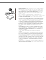
Instructions for Recycling the Packaging
If you no longer need the packaging after successful installation of the equipment, you should
return it for recycling, as it is a valuable source of secondary raw material. Minebea Intec products are
packaged to ensure safe shipment using environmentally friendly materials. For information on
recycling options, including recycling of old weighing equipment, contact your municipal waste
disposal center or local recycling depot. Make sure you remove the batteries before disposing
of the equipment. Rechargeable batteries are toxic waste and as such may not be disposed of with
normal household waste. Contact your municipal waste disposal center or local recycling depot
for details on the proper disposal of batteries.
Model-specific Information: Serial Number Coding
The month and year of manufacture are encoded in the serial number as follows:
Y M M x x x x x
Y= Year:
1 2000–2006
2 2007–2013
3 2014–2020
4 2021–2027
5 2028–2034
6 2035–2041
7 2042–2048
8 2049–2055
9 2056–2062
The first digit represents a 7-year period as indicated in the table above. The next 2 digits repre-
sent the month. The months are numbered consecutively, starting with 13, over the entire 7-year
period. Thus the number representing the month also indicates the specific year of manufacture.
2000 13–24
2001 25–26
...
Example:
113xxxxx -> January 2000
The individual devices are numbered consecutively in the last 5 digits, starting from 00000 again
at the beginning of each month.

10
Inhalt
10 Zeichenerklärung
10 Verwendungszweck
11 Sicherheits- und Warnhinweise
11 Garantie
12 Aufstellhinweise
14 Installation
17 Pflege und Wartung
Folgende Symbole werden in dieser Anleitung verwendet:
§steht vor Handlungsanweisungen
$steht vor Handlungsanweisungen, die nur unter bestimmten
Voraussetzungen ausgeführt werden sollen
> beschreibt das, was nach einer ausgeführten Handlung
geschieht
– steht vor einem Aufzählungspunkt
!weist auf eine Gefahr hin
Die Sicherheits- und Warnhinweise sind in ihrer Gesamtheit
bei der Installation, beim Betrieb, bei der Wartung und
Reparatur des Gerätes zu beachten. Diese Hinweise sollten
von allen Beteiligten verstanden und stets griffbereit sein.
Die Sicherheits- und Warnhinweise in den Unterlagen der
angeschlossenen elektrischen Betriebsmittel wie z.B.:
Auswerteeinheit (Indikator), sind ebenso zu beachten. Diese
Sicherheits- und Warnhinweise sind ggf. durch den
Betreiber zu ergänzen. Das Bedienpersonal ist entsprechend
einzuweisen.
Verwendungszweck
Die Wägeplattform und das angeschlossene Auswertegerät
(Indikator) sind ausschließlich zum Wägen bestimmt.

11
Sicherheits- und Warnhinweise
Die Wägeplattform erfüllt die Anforde-
rungen der EG-Richtlinie 94/9/EG für
Geräte der Gerätegruppe II, Kategorie 2
und ist gemäß EG-Baumusterprüf-
bescheinigung KEMA 02ATEX1010X
gekennzeichnet mit:
hII 2 GD EEx ib IIC T4...T6 T135...155°C.
Ferner erfüllt die Wägeplattform die
Anforderungen der EG-Richtlinien für
elektromagnetische Verträglichkeit und
elektrische Sicherheit (siehe Konformi-
tätserklärungen). Ein unsachgemäßer
Gebrauch kann zu Schäden an Personen
und Sachen führen.
– Die Wägeplattform kann innerhalb oder
außerhalb von Gebäuden eingesetzt
werden. Diese Wägeplattform darf nicht
im medizinischen Bereich (als Medizin-
produkt) eingesetzt werden.
– Die Wägeplattform darf in explosions-
gefährdeten Bereichen der Zone 1, 2,
21 oder 22 (gas- und staubexplosions-
gefährdete Bereiche) eingesetzt werden.
Die derzeit gültigen Normen und Vor-
schriften (z.B.: ElexV, EN60079-14) für
die Installation von Geräten in den
genannten Zonen sind einzuhalten.
Der Einsatz im explosivstoffgefährdeten
Bereich muss im Einzelfall geprüft
werden.
– Die Wägeplattform ist nur von
qualifizierten Personal einzusetzen und
zu betreiben. Der Einsatzbereich der
Wägeplattform ist in der
Baumusterprüfbescheinigung definiert.
– Die Wägeplattformen nicht unnötig
extremen Temperaturen, aggressiven
chemischen Dämpfen, Feuchtigkeit,
Stößen und Vibrationen aussetzen. Die
zulässige Umgebungstemperatur im
Betrieb beträgt –10°C bis 40°C.
– Wird die Lastplatte mit einem
Saugheber angehoben, Handschuhe,
Sicherheitsschuhe und Sicherheits-
kleidung tragen. Verletzungsgefahr!
Diese Arbeiten dürfen nur von zu-
verlässigen und dazu beauftragtem
Personal durchgeführt werden.
– Bei den Modellen ab einer Baugröße
von 1000 +1000 mm sind
Aufhängepunkte vorgesehen. Bei einem
Transport oder Anheben der Waage/
Lastplatte mit einem Kran nicht unter
die Last treten.
– Die entsprechenden Unfallverhütungs-
vorschriften beachten.
– Den Klemmanschlusskasten und die
Lastaufnehmer beim Transport nicht
beschädigen.
– Die Installation des Gerätes in der Zone
1, 2, 21 oder 22 ist von einer Fachkraft
durchzuführen. Als Fachkraft gilt eine
Person, die mit der Montage, Inbetrieb-
nahme und Betrieb der Anlage vertraut
ist. Die Fachkraft verfügt über die
entsprechende Qualifikation, die ein-
schlägigen Bestimmungen und Vor-
schriften sind Ihr bekannt. Bei Bedarf
den Händler oder Sartorius Kunden-
dienst ansprechen. Bei unsachgemäßer
Installation entfällt die Gewährleistung.
Alle in der Baumusterprüfbescheini-
gung genannten Beschränkungen sind
einzuhalten. Ein Betrieb der Wäge-
plattform über die Beschränkungen
hinaus ist nicht zulässig und gilt als
nicht bestimmungsgemäßer Gebrauch.
– Die Anlage in angemessenen Abständen
durch eine dafür entsprechend aus-
gebildete Fachkraft auf ihre ordnungs-
gemäße Funktion und Sicherheit über-
prüfen lassen.
– Das Öffnen des Klemmanschlusskasten
darf nur von geschulten Service-
technikern nach Sartorius-Richtlinien
erfolgen!
– Alle Wartungs-, Reinigungs- und
Reparaturarbeiten an der
Wägeplattform sind grundsätzlich im
spannungsfreiem Zustand des Gerätes
durchzuführen. Jeder Eingriff in die
Geräte (außer von Sartorius autorisierte
Personen) führt zum Verlust aller
Garantieansprüche. Nur original
Sartorius-Ersatzteile verwenden!
– Die Geräte entsprechend ihrem
IP-Schutz – nach DIN EN 60529
(VDE 0470 Teil 1) – behandeln. Der
IP-Schutz der Wägeplattform beträgt
IP67. IP-Schutz bei der Reinigung der
Geräte einhalten. Der IP-Schutz ist nur
bei fachgerecht eingebauter Gummi-
dichtung am Klemmanschlusskasten
und fester Anschlussverbindung an der
Kabelbverschraubung gewährleistet.
Bei unsachgemäßer Installation entfällt
die Gewährleistung.
– Bei Verwendung fremdbezogener Kabel
auf die Pinbelegungen achten. Die
Anschlüsse des Kabels deshalb vor
Anschluss an die Sartorius Geräte nach
dem entsprechenden Verbindungsplan
prüfen und die abweichend belegten
Leitungen trennen. Nicht von Sartorius
gelieferte Kabel unterliegen der
Verantwortung des Betreibers.
– Beim Einsatz der Waage im explosions-
gefährdeten Bereich dürfen alle Strom
führenden Kabel nur im strom-/
spannungslosen Zustand von der
Waage gezogen oder aufgesteckt wer-
den. Vor Anschluss oder Trennen von
Kabeln die Waage vom Netz trennen.
– Elektrostatische Aufladung vermeiden,
Potentialausgleichsklemme (am
Klemmanschlusskasten) anschließen.
– Eine Unterbrechung der Potential-
ausgleichsleitungen ist untersagt.
– Erscheint Ihnen ein gefahrloser Betrieb
nicht mehr gewährleistet, die Plattform
von der Betriebsspannung trennen und
gegen weitere Benutzung sichern (z.B.
bei einer Beschädigung). Unfallver-
hütungsvorschriften beachten, Bedien-
personal entsprechnd einweisen.
– Die Ummantelung aller Verbindungs-
kabel, sowie die der Litzen der inneren
Verdrahtungen bestehen aus PVC-
Material. Chemikalien, die dieses
Material angreifen, müssen von diesen
Leitungen ferngehalten werden.
– An dem Einsatzort der Waage ist darauf
zu achten, dass die Wägeplattform
nicht Stoffen ausgesetzt wird, die
Chlorionen freisetzen. Anderenfalls sind
Schutzmaßnahmen durch den Betreiber
vorzunehmen, die durch regelmäßige
Kontrollen auf ihre Wirksamkeit zu
überprüfen sind.
– Verwendet werden Wägezellen/Last-
zellen der Firma Global Weighing
Technologies mit den Typenbe-
zeichnungen 011299/... bis 011311/...
und zugehöriger EG-Baumusterprüf-
bescheinigung Nr. PTB 02 ATEX 2061.
Die Kennzeichnung lautet:
hII 2 G EEx ia IIC T4/T6.
Die Kenndaten sind der beigefügten
EG-Baumusterprüfbescheinigung zu
entnehmen. Die Wägezelle ist nur von
qualifizierten Personal einzusetzen und
zu verwenden. Der Einsatzbereich ist
entsprechend den technischen Daten
und den aufgeführten Sicherheits-
bestimmungen definiert. Ein Betrieb
der Wägezelle über die in der Bau-
musterprüfbescheinigung angegebenen
Daten hinaus ist nicht zulässig und
gilt als nicht besimmungsgemäßer
Gebrauch. Alle in der Baumusterprüf-
bescheinigung genannten Beschrän-
kungen sind strikt einzuhalten.
Garantie
Den erweiterten Garantieanspruch nicht
verschenken. Die vollständig ausgefüllte
Garantieanmeldung an Sartorius
zurücksenden.
Garantie- und
Service-Scheckheft
Achtung!
Garantieanmeldung (Scheck Nr.3) sofort absenden
Sartorius AG, Wägetechnik
R
e
g.
No
.
1
94
4
0-
0
3
M
A
N
A
G
E
M
E
N
T
S
Y
S
T
E
M
C
E
R
T
I
F
I
E
D

1212
Aufstellhinweise
§Für die Wägeplattform einen geeigneten Aufstellort einrichten. Der Aufstellort sollte
trocken, waagerecht und eben sein. Der Arbeitstemperaturbereich liegt zwischen –10°C
und +40°C. Die zulässige Bodenbelastung muß für die Wägeplattform und deren
Belastung ausreichend sein.
Bei stark befahrenen Bereichen des Aufstellortes (z.B. Gabelstapler) ist ein Schutzrahmen
um die Wägeplattform aus Winkeleisen zu installieren.
Die Wägeplattfrom nicht unnötig extremen Temperaturen, Feuchtigkeit, Stössen oder
Vibrationen aussetzen, die eine Beschädigung zur Folge haben könnten.
§Die Luftblase der Libelle muss sich in Kreismitte befinden.
§Mit Hilfe der Stellfüße die Libelle einstellen.
§Prüfen, ob alle Stellfüße Bodenkontakt haben.
> Alle Stellfüße müssen gleichmäßig belastet sein!
§Die Kontermuttern an den Stellfüßen mit einem Maulschlüssel lösen.
> Stellfüße einstellen:
Herausdrehen der Stellfüße (rechtsherum drehen) hebt die Wägeplattform an.
Hineindrehen der Stellfüße (linksherum drehen) senkt die Wägeplattform ab.
§Nach Ausrichten der Wägeplattform die Kontermuttern festdrehen.
Kleine Plattformen (1 Lastzelle): gegen den Plattformrahmen,
Große Plattformen (4 Lastzellen): gegen den Plattfromfuß.
§Steht die Wägeplattform im explosionsgefährdeten Bereich, muss sie geerdet werden
(PA-Anschluss). Die Erdung soll von einem Fachmann ausgeführt werden.
Eine Erdungsmöglichkeit ist an jeder Bauform der Combics-Wägeplattform vorhanden.
Sie befindet sich unterhalb der Waagschale am Klemmanschlusskasten oder am
Untergestell der Wägeplattform. Sie ist mit dem nebenstehenden Symbol als Erdungs-
anschluss gekennzeichnet.
Die Erdung erfolgt über einen Gewindebolzen, eine Schraubklemme oder ist als
Bohrung vorhanden. Bei der Bohrung muss die Erdung mit einer Edelstahlschraube und
Mutter vorgenommen werden. Zum Schutz vor Selbstlösen sollte eine Zahnscheibe
untergelegt sein. Das Erdungskabel muss einen Mindestquerschnitt von 4 mm2haben
und mit einer geeigneten Ringöse ausgestattet sein.
Alle Geräte und Zubehörteile mit dem Potentialausgleich (PA) verbinden.

13
Aufstellbedingungen
Vor der Inbetriebnahme muß sichergestellt sein, dass das Netzkabel des zugehörigen
Netzgerätes ordnungsgemäß am Netz angeschlossen ist. Alle Geräte mittels Masse-
verbindungskabel (nicht im Lieferumfang enthalten) über die an den Geräten vorhande-
nen Potentialausgleichsklemmen an den Potentialausgleich (PA) anschließen.
Der Kabelquerschnitt richtet sich nach den zutreffenden nationalen Bestimmungen.
Die Installation muss von einer dafür ausgebildeten Fachkraft vorschriftsmäßig und nach
den Regeln der Technik durchgeführt werden.
Für das Anschlusskabel zum Auswertegerät dürfen nur von freigegebene Kabel
und Kabellängen verwendet werden, die die Beschränkungen der Kabellängen aufgrund
der Kapazitäts- und Induktivitätswerte (siehe Anlage zur EG-Baumusterprüfbescheini-
gung) und des EMV-Verhaltens berücksichtigen.
Die Anlage erstmalig nur dann in Betrieb nehmen, wenn sichergestellt ist, dass der
Bereich nicht explosionsgefährdet ist. Zeigen sich bei dieser Inbetriebnahme durch Trans-
portschäden Abweichungen (keine Anzeige, keine Hinterleuchtung, so ist die Anlage
vom Netz zu trennen und der Service zu informieren.
Die Kenndaten Ui, Li, Pi, Ta, Temperaturklasse, Ci, Li der Wägeplattform befinden sich in
der EG-Baumusterprüfbescheinigung. Dort ist auch angegeben, welche Auswertegeräte
(Indikatoren) an die Wägeplattform angeschlossen werden dürfen. Bei Anschluss eines
Indikators müssen die Kenndaten berücksichtigt werden. Die Ci- und Li-Werte gelten für
Wägeplattformen mit 3 m langem Anschlusskabel zum Indikator. (Siehe auch „Nachweiss
zur Eigensicherheit“ im Anhang dieser Anleitung.
Die explosionsgeschützte Wägeanlage ist nach den anerkannten Regeln der Technik zu
errichten. Dabei sind die entsprechenden nationalen Gesetze/Vorschriften (z.B. ElexV,
VbF, EX-RL, DIN EN 60079-14, DIN EN 5281-1-2, DIN VDE 0166, DIN VDE 0100,
DIN VDE 0101, DIN VDE 0800) zu beachten. Insbesondere sind die „Speziellen
Bedingungen für den sicheren Gebrauch“ (Punkt 17 der EG-Baumusterprüfbescheinigung
der KEMA) einzuhalten. Nationale Vorschriften zur Unfallverhütung und zum
Umweltschutz sind einzuhalten.
Vor Inbetriebnahme der Wägeanlage im explosionsgefährdeten Bereich muss der
ordnungsgemäße Zustand der Anlage durch eine Elektrofachkraft oder unter Leitung und
Aufsicht einer Elektrofachkraft überprüft werden (§12 ElexV). Prüfen, ob die zuständige
Behörde (z.B. Gewerbeaufsichtsamt) informiert werden muss. Auch während des Betriebes
sind Prüfungen der Anlage erforderlich. Die Fristen dazu sind so zu bemessen, dass ent-
stehende Mängel, mit denen gerechnet werden muss, rechtzeitig erkannt werden. Die
Prüfungen sind mindestens alle drei Jahre durchzuführen. Bei der Installation und
während des Betriebes sind die entsprechenden Auflagen (z.B. §13 ElexV, DIN VDE 0105
Teil 9, Richtlinien der Berufsgenossenschaft) zu erfüllen. Bei den Prüfungen sind die sich
hierauf beziehenden dem Stand der Technik entsprechenden Regeln zu beachten.
Jeder Eingriff in das Gerät (außer durch von autorisierte Personen), sowie
unsachgemäße Installationen und Bedienung führt zum Verlust der Ex-Zulassung sowie
aller Garantieansprüche.

14
Installation
§Verbindungskabel der Wägeplattform mit dem geeigneten Auswertegerät verbinden,
z.B.: FCT01-X.
Hinweis:
Die PG-Verschraubung ist bei den Auswertegeräten bereits vormontiert.
Alle Arbeiten an der Verschraubung sehr sorgfältig ausführen!
§Verbindungskabel abisolieren und montieren.
– Schraubkappe der PG-Verschraubung abschrauben und auf das Kabel stecken.
– Das Kabel abisolieren (lt. Zeichnung). Die Schirmung (1) muß Kontakt mit den
Klemmen (2) haben. Schirmung ca. 3–4 mm über den O-Ring legen (siehe Zeichnung).
– Adern (3) des Kabels ca. 15 cm lang lassen, so dass diese montiert werden können.
– Kabel durch die PG-Verschraubung stecken.
– Kontakt der Klemmen mit der Schirmung kontrollieren. Die Masseverbindung erfolgt
über die Abschirmung!
– Schraubkappe festschrauben.
§Adern des Kabels an der Klemmleiste montieren
– Das Kabel abisolieren. Adern des Kabels entsprechend lang lassen, dass diese montiert
werden können.
– Adernenden ca. 1 cm abisolieren und mit Aderendhülsen versehen.
– Alle Adern ab der PG-Verschraubung mit dem beigelegten Schlauch zusätzlich über-
ziehen. Die dann noch freiliegenden Adern sollten eine Länge von ca. 5 cm bis zur
Klemmleiste nicht überschreiten.
– Adern fest an den Klemmen verschrauben (blau = Plus, braun oder schwarz = Minus)
Farbbelegung der Anschlusskabel der Wägeplattformen, Modelle CAPXS..
Nr. Signalbez. Bedeutung Aderfarbe des Anschlusskabels
1 BR_POS Brückenspeisespannung (+) blau
2 SENSE_POS Sense (+) grün
Brückenspeisespannung
3 OUT_POS Messspannung positiv weiss
4 OUT_NEG Messspannung negativ rot
5 SENSE_NEG Sense (–) grau
Brückenspeisespannung
6 BR_NEG Brückenspeisespannung (–) schwarz oder braun
§Mit dem Schraubendreher die Schrauben der Klemmleiste fest anziehen.
Hinweis für FCT01-X:
Die Brückenspeisespannungen sind jeweils durch 62 mA Sicherungen geschützt.
Damit die Sicherungen bei falscher Montage nicht ansprechen, muss ein Widerstand
zwischen Pin 1 und Pin 6, Pin 1 und Gehäuse und Pin 6 und Gehäuse größer als
140 Ohm gemessen werden. Pin 1 und Pin 2, sowie Pin 5 und Pin 6 müssen niederohmig
miteinander verbunden sein.

15
Typenschlüssel (CAPXab - cd - e):
Familienname Material Anzahl der Lastbereich in kg Abmessungen Auflösung
Lastzellen Siehe Tabelle 2 Siehe Tabelle 1 Siehe Tabelle 2
CAPX.. a b c d e
Combics S = Edelstahl 1 = eine Lastzelle
Analog 4 = vier Lastzellen 3
Plattform 6
15
30
60
150
300
600
1500
3000
Tabelle 1, Modellspezifische Daten/Abmessungen:
Kennung DC ED FE GF IG LL NL RN RR WR
Breite (mm) 240 300 400 500 600 1000 1000 1250 1500 1500
Länge (mm) 320 400 500 650 800 1000 1250 1500 1500 2000
Kabellängen (Anschlusskabel)
Länge (m) ca. 1,5 1,5 3,0 3,0 3,0 6,0 6,0 6,0 6,0 6,0
Tabelle 2, Auflösungen:
1 Wägebereich 2 Wägebereiche*
-L -I -LCE -NCE 2 +3000e
Wäge- Wäge- Wäge- Auflösung Wäge- Auflösung
bereich 15000d 30000d 1+3000e bereich bereich 1 Bereich 1 bereich 2 Bereich 2
in kg in g in g in g in kg in kg in g in kg in g
3 0,2 0,1 1 3 1,5 0,5 3 1
6 0,50,22 63162
15 1 0,5 5 15 6 2 15 5
30 2 1 10 30 15 5 30 10
60 5220 6030106020
150 10 5 50 150 60 20 150 50
300 20 10 100 300 150 50 300 100
600 50 20 200 600 300 100 600 200
1500 100 50 500 1500 600 200 1500 500
3000 200 100 1000 3000 1500 500 3000 1000
* die zugelassenen Wägebereiche für den eichpflichtigen Verkehr sind in der Konformitätserklärung aufgelistet. Bei Geräten mit zwei
Wägebereichen (2+3000e) ist der jeweilige Wägebereich nicht verschiebbar. Wird im höheren Wägebereich gewogen, so bleibt die
niedrigere Auflösung erhalten.
Beispiel: CAPXS4-3000WR-NCE = Combics Analog Plattform in Edelstahlausführung mit 4 Lastzellen, Wägebereich 3000 kg, 2+3000e
in eichfähiger Ausführung.

16
Betriebsgrenzen
Die Höchstlast der Wägeplattformen sollte nicht überschritten werden.
Abhängig von der aufgelegten Last (mittig, seitlich, einseitige Eckenlast) ist die
Höchstbelastung der Wägeplattform.:
Modell Mitte Seite Ecke
DC 50 35 20
ED 130 85 45
FE 300 200 100
GF 450 300 150
IG 900 600 300
LL 4500 3000 1500
NL 4500 3000 1500
RN 4500 3000 1500
RR 4500 3000 1500
WR 4500 3000 1500
!Kapitel: Sicherheits- und Warnhinweise beachten.

17
Pflege und Wartung
Reinigung
$Vor der Reinigung, Wartung oder Reparatur die Waage von der Betriebsspannung trennen.
Die Wägeplattform regelmäßig von Staub befreien (siehe EG-Baumusterprüfbescheinigung)
$Steht die Waage in einem trockenen Raum, die Wägeplattform feucht abwischen. Es können haus-
haltsübliche Reinigungsmittel verwendet werden. Die Angaben des Herstellers berücksichtigen.
$Die Stellfüße sind mit Gummipuffer überzogen. Diese dürfen im Ex-Bereich nur mit einem
feuchten Tuch gereinigt werden. Elektrostatische Aufladung wird somit vermieden.
!Konzentrierte Säuren und Laugen, sowie Lösungsmittel und reiner Alkohol dürfen nicht
verwendet werden.
$Steht die Waage in einem Nassraum, die Wägeplattform mit einem weichem Wasserstrahl (max.
60°C) von oben reinigen.
!Die Reinigung der Wägeplattform mit einem Hochdruckreiniger ist unzulässig.
> Bei Reinigung mit zu heissem oder kaltem Wasser kann sich durch den Temperaturunterschied
Schwitzwasser im Gerät bilden. Schwitzwasser kann zu Fehlfuktionen im Gerät führen.
$Ist die Waage in einer Grube eingebaut, darauf achten, das sich kein Schmutz zwischen den Rand
der Grube und die Wägeplattform setzt. Messfehler können so vermieden werden.
$Schmutz am Grubenboden regelmäßig entfernen.
Reinigung des Innenraumes der Wägeplattform
$Bei Verschmutzung des Innenraumes der Wägeplattfrom ist die Lastplatte abzunehmen.
Bei Modellen ab der Grösse 1000 +1000 mm ist besondere Vorsicht geboten.
!Sicherheitshinweise beachten.
$Innenraum mit Druckluft ausblasen, oder mit weichem Wasserstrahl ausspülen (max. 60°C).
Besonders darauf achten, das sich kein Schmutz in den Spalt der Überlastsicherung setzt (Spalt
zwischen dem Lastaufnehmer und der Anschraubplatte).
Korrosive Umgebung
$Korrosionsauslösende Substanzen regelmäßig entfernen.
Entsorgungshinweise
Wird die Verpackung nicht mehr benötigt, so kann diese der örtlichen Müllentsorgung zugeführt
werden. Die Verpackung besteht durchweg aus umweltverträglichen Materialien, die als wertvolle
Sekundärrohstoffe der örtlichen Müllentsorgung zugeführt werden sollten. Für Entsorgungs-
möglichkeiten von Teilen oder ausgedienten Geräten, die örtliche Gemeinde- bzw. Stadtverwaltung
ansprechen. Akkus sind generell vor der Verschrottung des Gerätes aus diesem zu entfernen.
Akkus sind Sondermüll und gehören nicht in den normalen Hausmüll. Die entsprechende
Sammelstelle für Sondermüll ansprechen.
Waagenspezifische Informationen/Codierung der Seriennummer
Das Herstelldatum des Gerätes ist in der Seriennummer codiert. Die Struktur ergibt sich
wie folgt:
JMM x x x x x
J Jahr
1 2000–2006
2 2007–2013
3 2014–2020
4 2021–2027
5 2028–2034
6 2035–2041
7 2042–2048
8 2049–2055
9 2056–2062
Die Jahresspalte J steht für die Jahresgruppennummer, die einen Zeitraum von jeweils 7 Jahren
definiert. Innerhalb jeder Jahresgruppe werden die Monate (M M) von 13 an hochgezählt.
2000 13–24
2001 25–26
...
Beispiel:
113xxxxx (Januar 2000)
xxxxx ist eine fortlaufende Nummer, die jeden Monat neu hochgezählt wird.

18
Sommaire
18 Signification des symboles
18 Description générale
19 Conseils de sécurité
19 Garantie
20 Conseils d’installation
22 Installation
25 Entretien et maintenance
Les symboles suivants sont utilisés dans ce mode d’emploi :
§indique une action qu’il est conseillé d’effectuer,
$indique une action qu’il est conseillé d’effectuer uniquement
sous certaines conditions,
> décrit ce que provoque l’action que vous venez d’effectuer,
– est placé devant une énumération,
!indique un danger.
Vous devez suivre l’ensemble des conseils de sécurité lors
de l’installation, pendant le fonctionnement, la maintenance
et la réparation de l’appareil. Ces conseils doivent être
compris par toutes les personnes concernées et toujours être
à portée de main.
Vous devez également suivre les conseils de sécurité se trou-
vant dans les documents du matériel électrique connecté,
comme par ex. l’indicateur. Ces conseils de sécurité doivent,
le cas échéant, être complétés par l’utilisateur. Le personnel
qui utilise l’appareil doit être informé en conséquence.
Description générale
La plate-forme de pesée et l’indicateur connecté sont
exclusivement destinés à effectuer des opérations de pesage.

19
Conseils de sécurité
La plate-forme de pesée est conforme
à la directive CE 94/9/CE concernant
les appareils du groupe d’appareils II,
catégorie 2 et elle est identifiée confor-
mément au certificat d’examen de
type CE KEMA 02ATEX1010X par le
marquage :
hII 2 GD EEx ib IIC T4...T6
T135...155°C.
En outre la plate-forme de pesée est
conforme aux directives CE concernant
la compatibilité électromagnétique et la
sécurité électrique (voir les déclarations
de conformité). Une utilisation non
conforme de l’appareil peut provoquer
des dommages et s’avérer dangereuse
pour l’utilisateur.
– La plate-forme de pesée peut être utili-
sée à l’intérieur ou à l’extérieur de
bâtiments. Cette plate-forme de pesée
ne doit pas être utilisée en environne-
ment médical (comme produit médical).
– La plate-forme de pesée peut être utili-
sée dans les domaines à risques
d’explosions de la zone 1, 2, 21 ou 22
(conditions ambiantes comportant des
risques d’explosions dues au gaz ou à
de la poussière). Veuillez respecter les
consignes de sécurité correspondantes
(par ex. EN60079-14).
L’utilisation dans un domaine à risques
d’explosions doit être examinée cas
par cas.
– La plate-forme de pesée ne doit être
utilisée que par du personnel qualifié.
Le domaine d’utilisation de la plate-
forme de pesée est défini dans le certifi-
cat d’examen de type.
– N’exposez pas inutilement les plates-
formes de pesée à des températures, des
dégagements chimiques corrosifs, de
l’humidité, des chocs ou des vibrations
extrêmes. La gamme de température
ambiante autorisée pendant le fonc-
tionnement est de –10°C à 40°C.
– Si le tablier est soulevé à l’aide d’un
élévateur à aspiration, prière de porter
des gants, des chaussures de sécurité
et des vêtements de sécurité. Risques de
blessures ! Ces travaux ne doivent être
effectués que par du personnel sûr et
chargé de les exécuter.
– Les modèles de grandes dimensions
(à partir de 1000 x 1000 mm) sont
équipés d’anneaux de levage. Lorsque
vous transportez ou soulevez la balan-
ce/le tablier avec une grue, veillez à
ne pas vous placer sous la charge.
– Respectez les directives concernant la
prévention des accidents.
– Lors du transport, veillez à ne pas
endommager la boîte de jonction de
câbles ni le récepteur de charge.
– L’installation de l’appareil dans la zone
1, 2, 21 ou 22 doit être effectuée par
un spécialiste. Un spécialiste est une
personne qui est familiarisée avec le
montage, la mise en service et le
fonctionnement de l’installation. Le
spécialiste dispose de la qualification
correspondante, il connaît les disposi-
tions et les directives en vigueur. En cas
de besoin, s’adresser au vendeur ou au
service après-vente Minebea intec. Toute
installation non conforme fait perdre
tout droit à la garantie. Toutes les limi-
tations mentionnées dans le certificat
d’examen de type doivent être respec-
tées. Un fonctionnement de la plate-
forme de pesée au-delà des limitations
n’est pas autorisé et est considéré
comme utilisation non conforme aux
dispositions.
– Faites contrôler régulièrement le bon
fonctionnement et la sécurité de l’ins-
tallation par un spécialiste ayant reçu
la formation nécessaire.
– Seuls des techniciens du service après-
vente ayant reçu la formation nécessaire
sont autorisés à ouvrir la boîte de jonc-
tion de câbles conformément aux direc-
tives de la société Minebea Intec!
– Toutes les opérations de maintenance,
de nettoyage et de réparation effec-
tuées sur la plate-forme doivent uni-
quement avoir lieu lorsque l’appareil
n’est pas sous tension. Toute manipula-
tion sur les appareils (sauf par du per-
sonnel agréé par Minebea Intec) a pour
conséquence la perte de tout droit à la
garantie. N’utilisez que des pièces de
rechange Minebea Intec!
– Respectez l’indice de protection IP des
appareils – selon DIN EN 60529
(VDE 0470 Partie 1). La protection IP
de la plate-forme de pesée est IP67.
Lors du nettoyage des appareils, respec-
tez la protection IP. La protection IP
correspondante est garantie unique-
ment si un joint en caoutchouc est ins-
tallé correctement à la boîte de jonction
de câbles et si les connexions aux pres-
se-étoupe sont fixes. Toute installation
non conforme fait perdre tout droit
à la garantie.
– En cas d’utilisation de câbles préparés
par d’autres, veuillez contrôler l’affecta-
tion des broches. C’est pourquoi vous
devez vérifier les schémas de câblage
correspondants du câble avant de le
connecter aux appareils Minebea Intec
et supprimer les branchements non
conformes. L’utilisateur engage sa
propre responsabilité concernant tout
raccordement de câbles non livrés
par Minebea Intec.
– En cas d’utilisation dans des domaines
à risques d’explosions, tous les câbles
conducteurs ne doivent être branchés
ou débranchés que lorsque la balance
est hors tension. Avant de connecter ou
de retirer des câbles, débrancher la
balance.
– Evitez les charges électrostatiques,
connectez la borne d’équipotentialité
(à la boîte de raccordement à bornes).
– Le conducteur de protection ne doit
pas être interrompu.
– S’il vous semble que la plate-forme ne
peut plus fonctionner sans danger,
veuillez la mettre hors service en la
débranchant du secteur et assurez-vous
qu’elle ne sera plus utilisée (par ex. en
cas de dommage). Suivez le règlement
de prévention des accidents et informez
le personnel en conséquence.
– La gaine de tous les câbles de raccorde-
ment ainsi que celle des câbles toronnés
des câblages intérieurs sont en PVC.
Tout produit chimique pouvant
attaquer cette matière doit être tenu
éloigné de ces câbles.
– Sur le lieu d’utilisation de la balance,
il faut veiller à ce que la plate-forme de
pesée ne soit pas exposée à des sub-
stances dégageant des ions de chlore.
Sinon l’utilisateur doit prendre des
mesures de protection et en vérifier
l’efficacité par des contrôles réguliers.
– Les capteurs utilisés sont fabriqués
par la société Global Weighing
Technologies : type 011299/... à
011311/... et certificat d’examen CE
de type noPTB 02 ATEX 2061.
Identification :
hII 2 G EEx ia IIC T4/T6.
Vous trouverez les données caractéris-
tiques dans le certificat d’examen CE de
type se trouvant en annexe. Le capteur
ne doit être utilisé que par du personnel
qualifié. Le domaine d’utilisation de la
plate-forme de pesée est défini dans les
fiches techniques et les consignes de
sécurité. Un fonctionnement du capteur
au-delà des données indiquées dans
le certificat d’examen de type n’est pas
autorisé et est considéré comme une
utilisation non conforme aux disposi-
tions. Respectez strictement toutes
les limitations mentionnées dans le cer-
tificat d’examen de type.
Garantie
Ne perdez pas les avantages de la
garantie totale. Veuillez contacter le
service après-vente Minebea Intec le plus
proche ou votre fournisseur pour plus
de renseignements. Si un bon de
garantie est joint à ce mode d’emploi,
veuillez le retourner dûment rempli
à votre centre de service après-vente
Minebea Intec le plus proche.

2020
Conseils d’installation
§Choisissez un endroit approprié pour l’installation de votre plate-forme de pesée.
Le lieu d’installation doit être sec, horizontal et plan. Les conditions réglementaires
d’utilisation doivent être entre –10 °C et +40 °C. La charge au sol autorisée doit être
suffisante pour la plate-forme de pesée et sa charge.
Si vous utilisez la plate-forme de pesée dans une zone où le va-et-vient d’engins indus-
triels, par exemple des chariots élévateurs, est particulièrement important, veuillez instal-
ler autour de la plate-forme de pesée un cadre protecteur composé d’équerres de fer.
N’exposez pas inutilement la plate-forme de pesée à des températures, de l’humidité, des
chocs ou des vibrations extrêmes qui pourraient l’endommager.
§La bulle d’air du niveau doit être centrée.
§Réglez la plate-forme de pesée sur le lieu d’installation avec les pieds de réglage.
§Vérifiez que tous les pieds de réglage sont bien en contact avec le sol.
> Tous les pieds de réglage doivent supporter une charge égale !
§Dévissez les contre-écrous des pieds de réglage avec une clé à fourche.
> Régler les pieds de réglage :
Dévissez les pieds de réglage (dans le sens des aiguilles d’une montre) pour surélever la
plate-forme de pesée.
Vissez les pieds de réglage (dans le sens inverse des aiguilles d’une montre) pour abaisser
la plate-forme de pesée.
§Après avoir mis à niveau la plate-forme de pesée, vissez les contre-écrous.
Petites plates-formes (1 capteur) : vers le châssis de la plate-forme.
Grandes plates-formes (4 capteurs) : vers le pied de la plate-forme.
§Si la plate-forme de pesée se trouve dans un domaine à risques d’explosions, elle doit
être mise à la terre (borne d’équipotentialité). La mise à la terre doit être effectuée par
un spécialiste.
Une possibilité de mise à la terre est présente sur tous les modèles de plates-forme de
pesées Combics.
Elle se trouve sous le tablier sur la boîte de raccordement à bornes ou sur le châssis de la
plate-forme de pesée. Elle est caractérisée comme prise de terre par le symbole ci-contre.
La mise à la terre s’effectue par un boulon fileté, une borne à vis ou est disponible
comme forage. En cas de forage, la mise à la terre doit être effectuée avec une vis en
acier inoxydable et un écrou. Pour éviter que la vis ne se desserre, il faut mettre une
rondelle crantée. Le câble de mise à la terre doit avoir une section minimum de 4 mm2
et être équipé d’un anneau circulaire approprié.
Relier tous les appareils et accessoires à la borne d’équipotentialité.
Sidan laddas...
Sidan laddas...
Sidan laddas...
Sidan laddas...
Sidan laddas...
Sidan laddas...
Sidan laddas...
Sidan laddas...
Sidan laddas...
Sidan laddas...
Sidan laddas...
Sidan laddas...
Sidan laddas...
Sidan laddas...
Sidan laddas...
Sidan laddas...
Sidan laddas...
Sidan laddas...
Sidan laddas...
Sidan laddas...
Sidan laddas...
Sidan laddas...
Sidan laddas...
Sidan laddas...
Sidan laddas...
Sidan laddas...
Sidan laddas...
Sidan laddas...
Sidan laddas...
Sidan laddas...
Sidan laddas...
Sidan laddas...
Sidan laddas...
Sidan laddas...
Sidan laddas...
Sidan laddas...
Sidan laddas...
Sidan laddas...
Sidan laddas...
Sidan laddas...
Sidan laddas...
Sidan laddas...
Sidan laddas...
Sidan laddas...
Sidan laddas...
Sidan laddas...
Sidan laddas...
Sidan laddas...
Sidan laddas...
Sidan laddas...
Sidan laddas...
Sidan laddas...
Sidan laddas...
Sidan laddas...
Sidan laddas...
Sidan laddas...
Sidan laddas...
Sidan laddas...
Sidan laddas...
Sidan laddas...
Sidan laddas...
Sidan laddas...
Sidan laddas...
Sidan laddas...
Sidan laddas...
Sidan laddas...
Sidan laddas...
Sidan laddas...
Sidan laddas...
Sidan laddas...
Sidan laddas...
Sidan laddas...
-
 1
1
-
 2
2
-
 3
3
-
 4
4
-
 5
5
-
 6
6
-
 7
7
-
 8
8
-
 9
9
-
 10
10
-
 11
11
-
 12
12
-
 13
13
-
 14
14
-
 15
15
-
 16
16
-
 17
17
-
 18
18
-
 19
19
-
 20
20
-
 21
21
-
 22
22
-
 23
23
-
 24
24
-
 25
25
-
 26
26
-
 27
27
-
 28
28
-
 29
29
-
 30
30
-
 31
31
-
 32
32
-
 33
33
-
 34
34
-
 35
35
-
 36
36
-
 37
37
-
 38
38
-
 39
39
-
 40
40
-
 41
41
-
 42
42
-
 43
43
-
 44
44
-
 45
45
-
 46
46
-
 47
47
-
 48
48
-
 49
49
-
 50
50
-
 51
51
-
 52
52
-
 53
53
-
 54
54
-
 55
55
-
 56
56
-
 57
57
-
 58
58
-
 59
59
-
 60
60
-
 61
61
-
 62
62
-
 63
63
-
 64
64
-
 65
65
-
 66
66
-
 67
67
-
 68
68
-
 69
69
-
 70
70
-
 71
71
-
 72
72
-
 73
73
-
 74
74
-
 75
75
-
 76
76
-
 77
77
-
 78
78
-
 79
79
-
 80
80
-
 81
81
-
 82
82
-
 83
83
-
 84
84
-
 85
85
-
 86
86
-
 87
87
-
 88
88
-
 89
89
-
 90
90
-
 91
91
-
 92
92


Minebea Intec CAPXS.. Models Stainless Steel Weighing Platforms for Use in Hazardous Areas/Locations Bruksanvisning
- Kategori
- Personliga skalor
- Typ
- Bruksanvisning
på andra språk
- español: Minebea Intec CAPXS.. Models Stainless Steel Weighing Platforms for Use in Hazardous Areas/Locations El manual del propietario
- português: Minebea Intec CAPXS.. Models Stainless Steel Weighing Platforms for Use in Hazardous Areas/Locations Manual do proprietário
- français: Minebea Intec CAPXS.. Models Stainless Steel Weighing Platforms for Use in Hazardous Areas/Locations Le manuel du propriétaire
- dansk: Minebea Intec CAPXS.. Models Stainless Steel Weighing Platforms for Use in Hazardous Areas/Locations Brugervejledning
- Nederlands: Minebea Intec CAPXS.. Models Stainless Steel Weighing Platforms for Use in Hazardous Areas/Locations de handleiding
Relaterade papper
-
 Minebea Intec Pallettenweegschaal/weegbrug voor explosiegevaarlijke ruimten IUXS4... Standaard en IUXS4...CE Bruksanvisning
-
 Minebea Intec Cable Junction Box PR 6130/68S Bruksanvisning
-
 Minebea Intec Models: MIS1... | MIS2... | MAPP1...4 | MAPS1...4 | MW1... | MW2...Display and Control Units, Weighing Platforms and Complete Scales for Use in Zone 2 and 22 Hazardous Areas Bruksanvisning
-
 Minebea Intec Cable Junction Box PR 6130/65S Bruksanvisning
-
 Minebea Intec Cable Junction Box PR 6130/64Sa Bruksanvisning
-
 Minebea Intec Data Output YDO06FC-X installatie in FC..BBE-X en in de serie FC..CCE-X.. | IS..BBE-X.., IS..CCE-X Bruksanvisning
-
Minebea Intec Cable Junction Box PR 6130/35S Bruksanvisning
-
 Minebea Intec Data Interface YDO05FC-X Installation in Series FC..BBE-X | FC..CCE-X and IS..BBE-X | IS..CCE-X Bruksanvisning


