Minebea Intec Models: MIS1... | MIS2... | MAPP1...4 | MAPS1...4 | MW1... | MW2...Display and Control Units, Weighing Platforms and Complete Scales for Use in Zone 2 and 22 Hazardous Areas Bruksanvisning
- Typ
- Bruksanvisning

Installation Instructions and Safety Information | Installation und Sicherheitshinweise |
Installation et conseils de sécurité | Istruzioni per l’installazione e la sicurezza |
Instalación e indicaciones de seguridad | Instalação e notas sobre segurança |
Installatie en veiligheidsinstructies | Installation og sikkerhedsanvisninger |
Installations- och säkerhetsanvisningar | Asennus ja turvallisuusohjeet
Minebea Intec Midrics|Signum: Option Y2
Models: MIS1... | MIS2... | MAPP1...4 | MAPS1...4 | MW1... | MW2...
Display and Control Units, Weighing Platforms and Complete Scales
for Use in Zone 2 and 22 Hazardous Areas
Modelle: MIS1... | MIS2... | MAPP1...4 | MAPS1...4 | MW1... | MW2...
Indikator, Wägeplattformen und Komplettwaagen für den Einsatz
in explosionsgefährdeten Bereichen der Zone 2 und 22
Modèles : MIS1... | MIS2... | MAPP1...4 | MAPS1...4 | MW1... | MW2...
Indicateurs, plates-formes de pesée et balances complètes destinés à être utilisés
dans des atmosphères explosibles des zones 2 et 22
Modelli: MIS1... | MIS2... | MAPP1...4 | MAPS1...4 | MW1... | MW2...
Indicatore, piattaforme di pesata e bilance complete per l’uso
in aree a rischio d’esplosione delle zone 2 e 22
Modelos: MIS1... | MIS2... | MAPP1...4 | MAPS1...4 | MW1... | MW2...
Visor, plataformas de pesaje y básculas completas para el uso
en áreas potencialmente explosivas de las zonas y 22
Modelos MIS1... | MIS2... | MAPP1...4 | MAPS1...4 MW1... | MW2...
Indicador, plataformas de pesagem e balanças completas para utilização
em áreas de perigo de explosão da Zona 2 e 22
Modellen MIS1... | MIS2... | MAPP1...4 | MAPS1...4 MW1... | MW2...
Indicator, weegplatformen en complete weegschalen voor gebruik
in explosiegevaarlijke ruimten van zone 2 en 22
Modeller MIS1... | MIS2... | MAPP1...4 | MAPS1...4 MW1... | MW2...
Indikator, vægtplatforme og kompaktvægte til indsats i eksplosionsfarlige
områder for zone 2 og 22.
Modellerna MIS1... | MIS2... | MAPP1...4 | MAPS1...4 | MW1... | MW2...
Indikator, vägningsplattformar och komplettvågar för insats
i explosionsutsatta områden av zon 2 och 22
Malli: MIS1... | MIS2... | MAPP1...4 | MAPS1...4 | MW1... | MW2...
Ilmaisin, punnitusalustat ja täydellinen vaaka käytettäväksi
vyöhykkeiden 2 ja 22 räjähdysvaarallisilla alueilla
98647-004-15
98647-004-15

2 Installation Instructions and Safety Information
English – page 3
Deutsch – Seite 14
Français – page 24
Italiano – pagina 34
Español – página 44
Português – página 54
Nederlands – pagina 64
Dansk – side 74
Sverige – sidan 84
Suomi – sivu 94
Certificate – page 100

Installation Instructions and Safety Information 3
Warnings and Safety PrecautionsContents
General View of the Equipment
Intended Use
Warnings and Safety Information
Installation Instructions
Getting Started
Ground (Earth)
Connection to AC Power
Care and Maintenance
Recycling
Documents
Intended Use
Midrics Models with Option Y2
Midrics equipment meets the highest requirements placed on
the accuracy and reliability of weighing results. Equipped with
Option Y2, Midrics models are suitable for use as category II 3
GD electrical apparatus in hazardous areas designated zone 2
(gases) or 22 (dusts).
Note:
Read these installation instructions and safety precautions
carefully before connecting the Midrics equipment to power
and putting it into operation.
In cases involving questions of
interpretation, the German-language version shall prevail.
The following symbols are used in these instructions:
§ indicates required steps
$ indicates steps required only under
certain conditions
> describes what happens after you have performed a particular
step
– indicates an item in a list
! indicates a hazard
Note:
Improper use or handling can result in damage and/or injury.
The scale may be installed and operated by qualified person-
nel only. Make sure you observe the warnings and safety pre-
cautions in their entirety during installation and operation, as
well as while performing maintenance and repair work on the
equipment. All laws, regulations, standards, accident preven-
tion rules and environmental protection requirements applica-
ble in your country must be followed.
It is important that all personnel using the equipment under-
stand these warnings and safety precautions, and have access
to the relevant documents at all times. Furthermore, the warn-
ings and safety information supplied with any electrical equip-
ment connected, such as peripheral devices, must be observed
as well. These warnings and safety precautions may have to
be supplemented by the equipment operator. All operating
personnel must be informed of any additions to these instruc-
tions.
Make sure the equipment is accessible at all times.
General Provisions for Installing Midrics Models Equipped
with Option Y2
Midrics models equipped with Option Y2 meet the require-
ments of EU Directive 2014/34/EU for Group II devices and
are suitable for use in zone 2 and 22 hazardous areas in
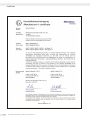
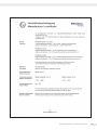
accordance with the declaration of conformity (see “Manufac-
turer’s Certificate”: SIS14ATEX004X/5X/6X at the end of this
manual). Furthermore, Midrics models meet the EC Directives
for electromagnetic compatibility (see “EU Declaration of Con-
formity” in the main manual).
– The area of use for which Midrics models are intended is
defined in the documents supplied. Make sure the restrictions
defined in those documents are observed. Operation outside
of these restrictions is not permitted, and is considered use of
the equipment for other than its intended purpose. Make sure
the safety instructions described in the drawing (for details,
see “Documents”: Drawing no. 36418-740-16) are followed.
– Before connecting or disconnecting data cables, control lines
or measuring lines to or from the device, make sure all equip-
ment is disconnected from power.
– If the equipment housing is opened by anyone other than per-
sons authorized by Minebea Intec , this will negate its con-
formity with regulations governing use in the stated Zone 2
and 22 hazardous areas and result in forfeiture of all claims
under the manufacturer‘s
warranty.

4 Installation Instructions and Safety Information
Installation Instructions
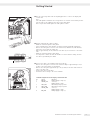
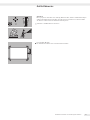
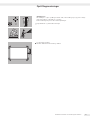
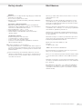
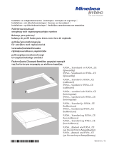
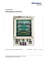
Setting up the Scale
Choose a suitable location where the equipment will not be exposed to drafts, heat
radiation, moisture or vibrations. Use a spirit level when adjusting the weighing plat-
form. Make sure to read these operating instructions carefully before connecting the
scale to power.
! Observe all warnings and safety precautions.
For verifiable models:
§ The air bubble must be centered within the circle on the level indicator.
°C

Installation Instructions and Safety Information 5
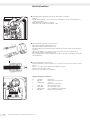
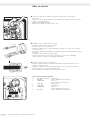
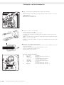
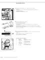
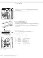
Getting Started
§ Use the connecting cable from the weighing platform to connect the display and
control unit.
Note:
The cable gland is installed at the factory. Please use extreme caution when perform-
ing any work on the equipment that affects this cable gland.
Use a torque wrench and tighten the cable gland to 5 Nm.
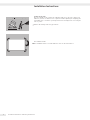
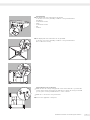
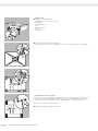
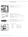
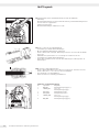
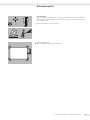
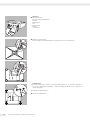
§ Prepare and install the cable as follows:
– Guide the cable through the cable gland.
– Close and tighten the cable gland in accordance with the applicable regulations.
– Remove the casing from a section of the cable end (see illustration). The shield (1)
must have contact with the clamps (2).
– Expose approximately 15 cm (4 inches) of the wires (3) for connection to the termi-
nals.
– Guide the cable through the cable gland.
– It is important to make sure that the shield is in contact with the clamps, because
the cable is grounded by the shield.
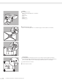
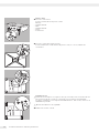
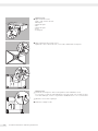
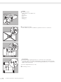
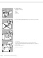
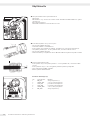
§ Connect the cable to the weighing platform as follows:
– Remove the casing from a section of the cable end. Expose approximately 5 cm (2
inches) of the isolated wires for installation.
– Remove the casing from approximately 1 cm (1/2 inch) of the wires and attach fer-
rules to the wire ends.
– Fit the ferrite ring over all wires.
– Attach the wires securely to the screw terminals.
Terminal Assignments in the Display and Control Unit
No. Signal Meaning
1 BR_POS Bridge supply voltage (+)
2 SENSE_POS Sense (+)
Bridge supply voltage
3 OUT_POS Measuring voltage positive
4 OUT_NEG Measuring voltage negative
5 SENSE_NEG Sense (-)
Bridge supply voltage
6 BR_NEG Bridge supply voltage (-)

6 Installation Instructions and Safety Information
Color Codes in the Connecting Cable for Model MAPP.. Weighing Platforms
Platform size Terminal assignment
in mm Designation No.: 1 2 3 4 5 6
320 + 240 DC 1) blue green white red gray black
320 + 240 DC 2) red white green gray black blue
400 + 300 ED 1) blue green white red gray black
400 + 300 ED 2) red white green gray black blue
500 + 400 FE 1) blue green white red gray black
500 + 400 FE 2) red white green gray black blue
650 + 500 GF blue green white red gray black
800 + 600 IG blue green white red gray black
800 + 800 II blue green white red gray brown
800 + 1000 LI blue green white red gray brown
1000 + 1000 LL blue green white red gray brown
1250 + 1000 NL blue green white red gray brown
1250 + 1250 NN blue green white red gray brown
1500 + 1250 RN blue green white red gray brown
1500 + 1500 RR blue green white red gray brown
2000 + 1500 WR blue green white red gray brown
1) HBM Load cell with gray cable 2) NMB Load cell with green cable
Color Codes in the Connecting Cable for Model MAPS.. Weighing Platforms
Platform size Terminal assignments
in mm Designation No.: 1 2 3 4 5 6
320 + 240 DC green blue white red brown black
400 + 300 ED green blue white red brown black
500 + 400 FE green blue white red brown black
650 + 500 GF green blue white red brown black
800 + 600 IG green blue white red brown black
800 + 800 II blue green white red gray brown
800 + 1000 LI blue green white red gray brown
1000 + 1000 LL blue green white red gray brown
1250 + 1000 NL blue green white red gray brown
1250 + 1250 NN blue green white red gray brown
1500 + 1250 RN blue green white red gray brown
1500 + 1500 RR blue green white red gray brown
2000 + 1500 WR blue green white red gray brown

Installation Instructions and Safety Information 7
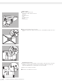
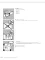
Ground (Earth)
§ The display and control unit must be grounded.
To do this, connect the grounding conductor to the ground terminal.
Installation:
– Toothed lock washer
– Cable
– Toothed lock washer
– Nut
– Locknut
§ The display and control unit must also be grounded.
To do this, connect the grounding conductor to the ground terminal.
Use a locknut if necessary.
Connecting the Scale to AC Power
! Make sure that the voltage rating printed on this unit is identical to your local line
voltage. If the voltage specified on the label does not match the rating or standard
you use, please contact your Minebea Intec office or dealer.
! Make sure to observe the safety instructions.
§ Connect the equipment to AC power.

8 Installation Instructions and Safety Information
Care and Maintenance Recycling
Cleaning
! Never use concentrated acids, alkali solutions, solvents or pure
alcohol to clean the equipment.
$ Do not allow liquids to penetrate the scale housing.
$ Use a brush or a soft, dry, lint-free cloth to clean the scale.
Storage and Shipping Conditions
$ The packaging used for shipping your Minebea Intec equipment
is optimally designed to prevent damage during transport.
It is a good idea to save the box and all parts of the packaging
for future storage or shipment of the equipment. Only the
original packaging provides the best protection for shipment.
$ Allowable storage temperature: –20°C to +75°C (–4°F to +167°F)
$ Allowable humidity during storage: max. 90%
$ Please see also the information under “Safety Inspection,”
below.
Safety Inspection
If there is any indication that safe operation is no longer
warranted; for example:
– If there is visible damage to the connecting cable,
– If the equipment no longer functions properly,
– If the equipment has been stored for a relatively long period
under unfavorable conditions,
– If the equipment has been subjected to rough handling during
shipment,
§ Make sure all warnings and safety precautions are observed, and
notify your nearest Minebea Intec Service Center or the Inter-
national Technical Support Unit based in Bovenden, Germany.
Maintenance and repair work may be performed only by autho-
rized Minebea Intec service technicians who have access to the
required maintenance manuals and have received the necessary
training.
! The seals affixed to this equipment indicate that only authorized
service technicians are allowed to open the equipment and per-
form maintenance work so that safe and trouble-free operation
of the equipment is ensured and the warranty remains in effect.
In Germany and many other countries (see www.minebea-intec.
com,
> Services > Downloads for details), Minebea Intec or the orga-
nization contracted by us takes care of the return and legally
compliant disposal of its electrical and electronic equipment
on its own.
In countries that are not members of the European Economic
Area (EEA) or where no Minebea Intec subsidiaries or dealerships
are located, please contact your local authorities or a commercial
disposal operator.
These products may not be placed with the household waste
or brought to collection centers run by local public disposal
operations – not even by small commercial operators.
For disposal in Germany and in the other member nations
of the European Economic Area (EEA), please contact our service
technicians on location or our Service Center in Bovenden,
Germany:
Minebea Intec Bovenden GmbH & Co. KG
Leinetal 2
37120 Bovenden, Germany
WEEE-Reg.-Nr. DE58091735
Prior to disposal and/or scrapping of the equipment, any batter-
ies should be removed and disposed of in local collection boxes.
Minebea Intec will not take back equipment contaminated with
hazardous materials (ABC contamination) – either for repair or
disposal.
Please refer to the accompanying leaflet/manual or visit our
Internet website (www.minebea-intec.com) for comprehensive
information that includes our service addresses to contact if you
plan to send your equipment in for repairs.
If you no longer need the packaging after successful installation
of the equipment, you should return it for recycling. The pack-
aging is made from environmentally friendly materials and is
a valuable source of secondary raw material.
The equipment, including accessories and batteries, does not
belong in your regular household waste.

Installation Instructions and Safety Information 9

10 Installation Instructions and Safety Information
Scale
---
---
Revision
03
Rele ased by
Revi ewed by
Written by
22.02.2021
22.02.2021
19.02.2021
Date
T. Hiller
T. Hiller
N am e Material
Titl e
Alteration
543604 Drawing number
Safety instructions
36418-740-16 (EN)
Shee t
1
R. Koch
of
4
The copying,
distribution and utilization of this document as well as the communication of its contents to others without expressed author
ization is
prohibited.
Offenders will be held liable for the payment of damages
. All rights reserved in the event of the grant of a patent, utility model or ornamental
design registration
.
Any informati on in this d ocumen t is subjec t to ch ange without notice and does not represent a commi tment on t he p art of Mineb
ea Intec
unless legally pr escri bed
.
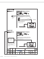
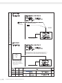
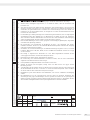
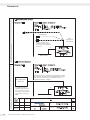
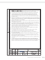
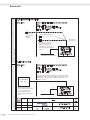
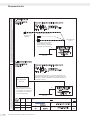
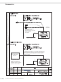
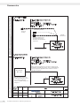
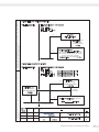
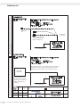
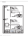
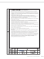
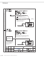
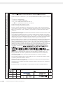
1. Power connection
Explosion-risk area zone 2 or zone 22Explosion-safe area
Indicator MIS.
or
complete scale
MW...-......-......
each + option Y2
2. Data transfer
PC, printer,
PLC, etc.
For data transfer only and, if required, supply for the
connected equipment (e.g. printer), there is no supply
voltage going from the connected equipment to the
indicator/complete scale
This equipment may also be
installed in zone 2 or zone 22
if they are suitable for
Category 3 as per the ATEX
Directive.
Gas: IIC, T4
Dust: IIIC, T80°C for indicators
IIIC, T100°C for complete scales
TAMB: -10°C to +40°C
Protect the connector of the
equipment supplied from
being disconnected. Secure
the emergency stop.
Connector of
equipment
supplied
Alternative
connections
Use explosion-protected
connector
Potential equalization
Potential equalization
6)
6) Indicator MIS.
or
complete scale
MW...-......-......
each + option Y2
Explosion-safe area
Gas: IIC, T4
Dust: IIIC, T80°C for indicators
IIIC, T100°C for complete scales
TAMB: -10°C to +40°C
Explosion-risk area zone 2 or zone 22

Installation Instructions and Safety Information 11
Scale
---
---
Revision
03
Rele ased by
Revi ewed by
Written by
22.02.2021
22.02.2021
19.02.2021
Date
T. Hiller
T. Hiller
N am e Material
Titl e
Alteration
543604 Drawing number
Safety instructions
36418-740-16 (EN)
Shee t
2
R. Koch
of
4
The copying,
distribution and utilization of this document as well as the communication of its contents to others without expressed author
ization is
prohibited.
Offenders will be held liable for the payment of damages
. All rights reserved in the event of the grant of a patent, utility model or ornamental
design registration
.
Any informati on in this d ocumen t is subjec t to ch ange without notice and does not represent a commi tment on t he p art of Mineb
ea Intec
unless legally pr escri bed
.
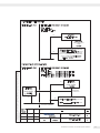
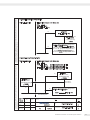
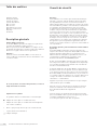
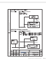
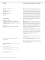
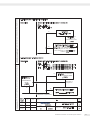
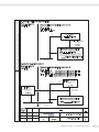
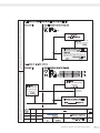
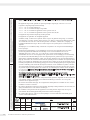
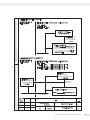
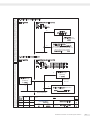
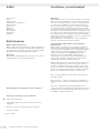
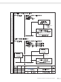
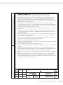
Explosion-risk area zone 2 or zone 22
Analog weighing platforms (load cells)
of the MAP ..-......-...... + option Y2 series
or other weighing platforms suitable for
zone 2 or 22 (category 3G or 3D) which
may be supplied with bridge rated
voltages of 9 VDC (minimum).
ADC output
with bridge rated
voltage
< 9 VDC
3. Analog load cells connection
Gas: IIC, T4
Dust: IIIC, T80°C
TAMB: -10°C to +40°C
4. Connection to external indicator
Potential equalization
Potential equalization
6)
6)
Indicator
MIS. + option Y2
Analog weighing platforms (load cells)
of the
MAP..-......-...... + option Y2 series
Explosion-risk area zone 2 or zone 22
Gas: IIC, T6
Dust: IIIC, T80°C for platform sizes DC, ED, FE
IIIC, T100°C for platform sizes GF, IG
TAMB: -10°C to +50°C for platform sizes DC, ED, FE
-10°C to +45°C for platform sizes GF, IG
Indicator
with bridge
rated voltage
12 VDC
Indicator
with bridge
rated voltage
12 VDC
6)
6)
6)
Alternative
connections
Explosion-safe area
Explosion-safe area

12 Installation Instructions and Safety Information
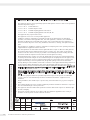
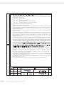
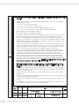
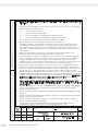
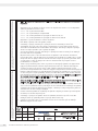
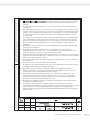
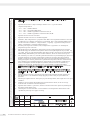
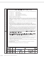
These safety instructions apply to the installation, operation, maintenance and repair
of the equipment
1. The equipment may be used zone 2 and 22 hazardous areas. In zone 22, the device is approved for use only
in the presence of non-conductive dusts. The permissible ambient temperature is –10°C to +40°C (14°F to
104°F). The equipment must be used indoors.
2. The indicator may not be used as a portable device.
3. Installation, operation, maintenance and repair of the equipment may only be performed by an
authorized technician and in compliance with applicable laws, rules and regulations, ordinances and standards.
In particular, make sure all work performed conforms to European Standards EN 60079-14 (Electrical appara-
tus for use in potentially explosive gas atmospheres) and EN 50281-1-2 (Apparatus for use in the presence of
combustible dusts). Installation, operation, maintenance and repair of the equipment may only be performed
when the equipment is completely disconnected from the power supply.
4. Make sure to follow the installation, operating, maintenance and servicing instructions given in the manuals
supplied.
5. The cable glands must be fastened using a torque of 5 Nm. Use only 3 Nm to fasten the power cable. The
external connecting cables must be installed in a protective tube and secured to prevent damage and stress
caused by strain. The cable connections in the hazardous area must be secured to prevent them from working
loose.
6. All metal parts (housing, column, etc.) must be electrically connected to the equipotential bonding
conductor (PA) so that any electrostatic charges can be conducted away from the equipment. The equipment
operator is obligated to connect a lead with a gauge of at least 4 mmÇ (cross section) to the PA terminal
(marked by the grounding symbol) located at the rear of the housing. The low resistance
of this connection to the PA busbar must be checked when the system is installed at the intended place of use.
The shielding of the connecting cables may only be used for grounding when no impermissible difference in
voltage is generated and the shielding is able to conduct the potentially occurring equipotential current.
7. Before opening the equipment, completely turn off the power or make sure that no potentially explosive
atmosphere is present in the area or any other explosion hazard in the surrounding area. Never connect or dis-
connect cables while the power is on in a hazardous area!
8. Use equipment only in the temperature ranges indicated. Avoid exposing the equipment to impermissible sources
of heat or cold. Avoid heat build-up. Make sure the equipment is properly ventilated.
9. Ensure proper installation to avoid vagrant current (e.g., magnetic fields).
10. Install the indicator (or the display and control unit supplied with the complete scale) in such a way that
mechanical hazard to the IP protection is kept to a minimum.
11. Make sure that the equipment is installed and operated without being exposed to impermissible UV radiation
(avoid direct exposure to sunlight).
12. Ensure that the voltage rating or power supply is identical to your local power rating. When connecting the
equipment to the power supply, the laws valid in your country must be observed. Be sure that the correct
power supply cable is used.
13. Prior to initial operation, make sure that there is no potentially explosive atmosphere or any other explosion
hazard in the surrounding area.
14. Avoid generating static electricity. Use only a damp cloth to wipe down the equipment.
The equipment operator shall be responsible for preventing any risks caused by static electricity.
15. If cables are connected at a later date, make sure the connectors are not corroded. Scale
---
---
Revision
03
Rele ased by
Revi ewed by
Written by
22.02.2021
22.02.2021
19.02.2021
Date
T. Hiller
T. Hiller
N am e Material
Titl e
Alteration
543604 Drawing number
Safety instructions
36418-740-16 (EN)
Shee t
3
R. Koch
of
4
The copying,
distribution and utilization of this document as well as the communication of its contents to others without expressed author
ization is
prohibited.
Offenders will be held liable for the payment of damages
. All rights reserved in the event of the grant of a patent, utility model or ornamental
design registration
.
Any informati on in this d ocumen t is subjec t to ch ange without notice and does not represent a commi tment on t he p art of Mineb
ea Intec
unless legally pr escri bed
.
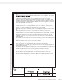
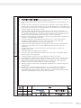
These safety instructions apply to installation, use, maintenance, and repair
1. The equipment may be used in potentially explosive atmospheres of zones 2 and 22. The permitted
ambient temperature range is:
-10°C to +40°C for MIS indicators
-10°C to +40°C for MW complete scales
-10°C to +45°C for MAP weighing platform sizes GF, IG
-10°C to +50°C for MAP weighing platform sizes DC, ED, FE
The equipment may only be used indoors.
2. The equipment is not to be used as portable equipment.
3. Installation, operation, maintenance, and repairs should only be performed by an authorized
specialist, in accordance with applicable laws, rules and regulations, ordinances, and standards. In
particular, the EN 60079-14 standard must be taken into account. Only when the equipment is
disconnected from all power sources may installation, maintenance, cleaning, and repair work take
place.
4. The information on installation, operation, maintenance and repair given in the operating instructions
supplied with the equipment must be observed.
5. The cable glands for the data cables must be tightened with a torque of 5 Nm. The cable gland for
the network cable must be tightened with a torque of 2.5 Nm cap and 1.5 Nm body . Attach
external connection cables as securely as possible to avoid damage and tensile loading. The cable
connections inside the explosion-risk area must be secured against loosening.
6. All metal parts (housing, column, etc.) must be galvanically connected to the equipotential bonding
so that any electrostatic charges can be conducted away from the equipment. For this purpose, the
operator is obligated to connect a conductor with a gauge of at least 4 mm² (cross section) to the
equipotential bonding connection (indicated by the ground symbol) located on the back of the
housing. During on-site installation, check if this connection to the equipotential bonding conductor is
of low resistance. When attaching the cable to the threaded bolt (indicator), two nuts and lock
washers must be used to avoid loosening of the clamp by pulling the grounding cable. Indicator and
weighing platform must be connected separately to the equipotential bonding when no metallic
connection, e.g. a column, is used.
7. Before opening the equipment, switch off the supply voltage, and make sure that the area is
not potentially explosive. Do not connect or disconnect any live cables inside an explosion -risk
area.
8. Only use the equipment within the specified temperature range. Avoid exposure to inadmissible
sources of heat or cold. Heat build-up should be avoided. Ensure that the equipment is well
ventilated.
9. During installation, take suitable steps to prevent stray electrical interference (e.g. due to magnetic
fields).
10.The indicator (display unit of the complete equipment) should be installed so that there is only a low
risk of mechanical danger to the IP protection.
11.The equipment must be installed and operated in a manner that avoids exposure to ultraviolet light
(no direct sunlight).
12.The power connection must be in accordance with the regulations applicable in the country of
operation. A correct power connection must be ensured.

Installation Instructions and Safety Information 13
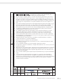
16. All external cables (including cables between load/weigh cells and junction box) are suitable only for secure
and protected installation and must be installed so that they cannot work loose or be damaged. If this cannot
be ensured, use cable glands, the round shape of which must have a radius of at least one quarter of the cable
diameter, but not more than 3mm, when measured across an angle of at least 75°.
17. If you plan to use other manufacturers’ cables (the operator shall be liable concerning all cable connections), a
suitability test must be performed. Tractive force of 10x the diameter of the cable (in mm) in N, but applied at
least at 100N for a 6-hour period, may not cause the cable to be pulled out by more than 6 mm. Be sure that
the pin assignment is correct. Remove any connections not needed.
18. All openings on the equipment housing must be closed by protective caps when not in use. Do not remove a
protective cap while the equipment is under current.
19. To use non-Minebea Intec equipment in Zone 2, be sure they have the appropriate gas and temperature
classes; for Zone 22, make sure they do not exceed the maximum surface temperature. The outputs must have
Ex nA electrical circuits.
20. Chemicals and other agents that can corrode or otherwise damage attack the housing seals and cable sheaths
must be kept away from the equipment. These agents include oil, grease, benzene, acetone and ozone. If you
are not sure about a certain substance, please contact the manufacturer.
21. At reasonable intervals, have your equipment installation checked for proper functioning and safety by a
trained and certified technician.
22. Do not expose the equipment to extreme shocks and vibrations.
23. If an in-use dust cover is utilized, ensure that no static electricity is generated. Use only a damp cloth
to clean it.
24. If your equipment needs to be repaired, use only original replacement parts supplied by the manufacturer.
25. If the equipment does not operate properly, unplug it immediately from line power (mains supply) and lock it
in a safe place to prevent further use for the time being.
26. Any tampering with the equipment by anyone, other than repair work done by authorized Minebea Intec ser-
vice technicians, will result in the loss of Ex conformity for Zones 2 and 22 and in the forfeiture of all claims
under the manufacturer‘s warranty. Only authorized specialists may open the equipment.
27. Modifications, including those to be carried out by Minebea Intec employees, may be permitted only after the
express written authorization has been obtained from Minebea Intec .
28. The data cables connected to the equipment are considered non-incendive circuits. The connections are
secured against accidental disconnection and may only be plugged in or disconnected when the power is
switched off completely. Outputs not used must be sealed so that the IP65 protection rating
is maintained. Do not expose the indicator to voltage transients.
Scale
---
---
Revision
03
Rele ased by
Revi ewed by
Written by
22.02.2021
22.02.2021
19.02.2021
Date
T. Hiller
T. Hiller
N am e Material
Titl e
Alteration
543604 Drawing number
Safety instructions
36418-740-16 (EN)
Shee t
4
R. Koch
of
4
The copying,
distribution and utilization of this document as well as the communication of its contents to others without expressed author
ization is
prohibited.
Offenders will be held liable for the payment of damages
. All rights reserved in the event of the grant of a patent, utility model or ornamental
design registration
.
Any informati on in this d ocumen t is subjec t to ch ange without notice and does not represent a commi tment on t he p art of Mineb
ea Intec
unless legally pr escri bed
.
13.Ensure that the area is not potentially explosive when commissioning the equipment for the first
time.
14. Avoid generating static electricity. Only use a damp cloth to clean the equipment. The operator
assumes responsibility for preventing any risks caused by electrostatic charging.
15.If cables are connected subsequently, make sure that the connections are not corroded.
16.All external cables (even cables between load cells and junction box) are only suitable for fixed
installation and must be laid fixed. Otherwise, use cable glands designed according to EN 60079-0
and rounded at an angle of 75° minimum and a radius at least equal to one-quarter of the diameter
of the cables, but without exceeding 3 mm.
17.Cables from third-party manufacturers (subject to the operator s responsibility) must be tested for
suitability: A tensile force of 10 times the diameter of the cable (in mm) in N, at least 100 N for
6 hours should not stretch the cable by more than 6 mm. Follow the correct pin assignment. Pay
attention to the wiring diagram. Remove connections that are not required.
18.Unused openings must be sealed using suitable cover caps (dummy plugs). Do not remove while
live.
19.When using external devices in zone 2 explosion-risk areas, observe the gas group and
temperature class; for zone 22 the maximum surface temperature must be observed. The outputs
must include the Ex nA electrical circuits.
20.Chemicals that can attack housing gaskets and cable sheathings must be kept away from the
equipment. These include oil, grease, benzine, acetone, and ozone. If you are uncertain, contact
the manufacturer.
21.The installation must be checked for correct function and safety by a trained and qualified person at
appropriate intervals.
22.Ensure the equipment is not exposed to strong jolts or vibrations.
23.When using a dust cover, avoid generating static electricity. Clean the device with a damp cloth.
24.In the event of repair, only use original spare parts supplied by the manufacturer.
25.If the installation does not operate properly, disconnect it from the supply voltage immediately and
secure it against further use.
26.Any modifications to the equipment (except by persons authorized by Minebea Intec) cause loss of
conformity for use in zone 2 and zone 22 explosion-risk areas and invalidate all guarantee claims.
Similarly, the equipment may only be opened by qualified and authorized personnel.
27.Modifications (including by Minebea Intec personnel) are subject to written approval.
28.The data cables to connected equipment are classed as flammable electrical circuits. The
connections are protected against involuntary disconnection and may only be connected and
disconnected when the equipment is switched off. Block unused outputs to guarantee the IP65
level of protection. Keep any voltage transients away from the equipment.

14 Installation Instructions and Safety Information
Inhalt Sicherheits- und Warnhinweise
Gerätedarstellung
Inhalt
Verwendungszweck
Sicherheits-und Warnhinweise
Aufstellhinweise
Inbetriebnahme
Erdung
Netzanschluss
Pflege und Wartung
Entsorgung
Dokumente
Verwendungszweck
Midrics-Modelle (Option Y2)
Die Midrics-Modelle erfüllen höchste Anforderungen an die
Zuverlässigkeit der Wägeergebnisse. Mit der Option Y2 sind die
Midrics-Modelle als elektrische Betriebsmittel der Kategorie II
3 GD geeignet für den Einsatz in Zone 2 (Gase) und Zone 22
(Stäube).
Hinweis:
Bevor die Midrics-Modelle angeschlossen und in Betrieb
genommen werden, die Installation und Sicherheitshinweise
aufmerksam durchlesen.
Im Auslegungsfall ist die deutsche Sprache maßgeblich.
Folgende Symbole werden in dieser Anleitung verwendet:
§ steht vor Handlungsanweisungen
$ steht vor Handlungsanweisungen, die nur unter bestimmten
Voraussetzungen ausgeführt werden sollen
> beschreibt das, was nach einer ausgeführten Handlung
geschieht
– steht vor einem Aufzählungspunkt
! weist auf eine Gefahr hin
Hinweis:
Ein unsachgemäßer Gebrauch kann zu Schäden an Personen
und Sachen führen. Das Gerät nur von qualifiziertem Personal
installieren und betreiben. Die Sicherheits- und Warnhinweise
in ihrer Gesamtheit bei Installation, Betrieb, Wartung und Repa-
ratur des Gerätes befolgen. Gesetze, Normen, Verordnungen,
Unfallverhütung und auch den Umweltschutz des jeweiligen
Landes befolgen. Diese Hinweise sollten alle Beteiligten verstehen
und die Dokumente stets griffbereit sein. Die Sicherheits- und
Warnhinweise in den Unterlagen der angeschlossenen elektri-
schen Betriebsmittel wie z.B. Zubehör, befolgen. Diese Sicher-
heits- und Warnhinweise muss der Betreiber ggf. ergänzen.
Das Bedienpersonal entsprechend einweisen. Die Einrichtungen
immer frei zugänglich halten!
Allgemeine Bestimmungen für die Installation der Midrics-
Modelle (Option Y2)
Die Midrics-Modelle mit Option Y2 erfüllen die Anforderungen
der EU-Richtlinie 2014/34/EU für Geräte der Gerätegruppe II,
und sind geeignet für den Einsatz in den explosionsgefährdeten
Bereichen der Zone 2 und 22 gemäß Konformitätserklärung,
siehe „Herstellererklärung“ SIS14ATEX004X/5X/6X am Ende die-
ser Anleitung. Ferner erfüllen die Midrics-Modelle die Anforde-
rungen der EG-Richtlinien für
elektromagnetische Verträglichkeit und elektrische Sicherheit
(siehe EU-Konformitätserklärung in der Betriebsanleitung).
- Der Einsatzbereich der Midrics-Modelle ist in den mitgeliefer-
ten Unterlagen definiert. Alle dort genannten Beschränkungen
sind einzuhalten. Ein Betrieb der Midrics-Modelle über diese
Beschränkungen hinaus ist nicht zulässig und gilt als nicht
bestimmungsgemäßer Gebrauch. Die Sicherheitshinweise gemäß
Zeichnung, siehe unter Dokumente: 36418-740-16
sind zu befolgen.
- Das Gerät ist geschützt gegen das Eindringen von festen
Fremdkörpern (IP67 -Schutz).
- Vor dem Anschluss und Trennen von Datenübertragungs-,
Steu er , und Messleitungen muss das Gerät unbedingt von der
Spannungsversorgung getrennt werden.
- Jeder Eingriff in das Gerät (außer durch von Minebea Intec
autorisierte Personen) führt zum Verlust der Ex-Konformität
für die Zone 2 und 22 sowie aller Garantieansprüche.

Installation Instructions and Safety Information 15
Aufstellhinweise
Aufstellort
Einen geeigneten Aufstellort ohne Luftzug, Wärmestrahlen, Feuchte und Erschütterungen
wählen. Die Wägeplattform mit Hilfe einer Wasserwaage ausrichten. Vor dem Anschluss
des Gerätes an das Stromnetz die Betriebsanleitung lesen.
! Sicherheits- und Warnhinweise beachten.
Für eichfähige Modelle:
§ Die Luftblase der Libelle muss sich in Kreismitte befinden.
°C

16 Installation Instructions and Safety Information
Inbetriebnahme
§ Verbindungskabel der Wägeplattform mit dem Indikator verbinden
Hinweis:
Die PG-Verschraubung ist bereits vormontiert. Alle Arbeiten an der Verschraubung sehr
sorgfältig ausführen!
Einen Drehmomentschlüssel verwenden.
Drehmoment dieser PG-Verschraubung: 5 Nm
§ Verbindungskabel abisolieren und montieren.
– Kabel durch die PG-Verschraubung stecken.
– PG-Verschraubung fachgerecht montieren
– Das Kabel abisolieren (lt. Zeichnung). Die Schirmung (1) muss Kontakt mit den Klemmen
(2) haben.
– Adern (3) des Kabels ca. 15 cm lang lassen, so dass diese montiert werden können.
– Kabel durch die PG-Verschraubung stecken.
– Kontakt der Klemmen mit der Schirmung kontrollieren. Die Masseverbindung erfolgt über
die Abschirmung!
§ Kabel der Wägeplattform montieren
– Das Kabel abisolieren. Adern des Kabels ca. 5 cm lang lassen, dass diese montiert werden
können.
– Adern ca. 1 cm abisolieren und mit Aderendhülsen versehen.
– Ferritring über alle Adern stecken.
– Adern fest an den Klemmen verschrauben
Anschlussbelegung des Indikators
Nr. Signalbez. Bedeutung
1 BR_POS Brückenspeisespannung (+)
2 SENSE_POS Sense (+)
Brückenspeisespannung
3 OUT_POS Messspannung positiv
4 OUT_NEG Messspannung negativ
5 SENSE_NEG Sense (-) Brückenspeisespannung
6 BR_NEG Brückenspeisespannung (-)

Installation Instructions and Safety Information 17
17
Farbbelegung der Anschlusskabel der Wägeplattformen, Modelle MAPP..
Plattformgröße Anschlussbelegung des Terminals
in mm Kennung Nr.: 1 2 3 4 5 6
320 + 240 DC 1) blau grün weiß rot grau schwarz
320 + 240 DC 2) rot weiß grün grau schwarz blau
400 + 300 ED 1) blau grün weiß rot grau schwarz
400 + 300 ED 2) rot weiß grün grau schwarz blau
500 + 400 FE 1) blau grün weiß rot grau schwarz
500 + 400 FE 2) rot weiß grün grau schwarz blau
650 + 500 GF blau grün weiß rot grau schwarz
800 + 600 IG blau grün weiß rot grau schwarz
800 + 800 II blau grün weiß rot grau braun
800 + 1000 LI blau grün weiß rot grau braun
1000 + 1000 LL blau grün weiß rot grau braun
1250 + 1000 NL blau grün weiß rot grau braun
1250 + 1250 NN blau grün weiß rot grau braun
1500 + 1250 RN blau grün weiß rot grau braun
1500 + 1500 RR blau grün weiß rot grau braun
2000 + 1500 WR blau grün weiß rot grau braun
1) Lastzelle mit grauem Anschlusskabel) 2) Lastzelle mit grünem Anschlusskabel
Farbbelegung der Anschlusskabel der Wägeplattformen, Modelle MAPS..
Plattformgröße Anschlussbelegung des Terminals
in mm Kennung Nr.: 1 2 3 4 5 6
320 + 240 DC grün blau weiß rot braun schwarz
400 + 300 ED grün blau weiß rot braun schwarz
500 + 400 FE grün blau weiß rot braun schwarz
650 + 500 GF grün blau weiß rot braun schwarz
800 + 600 IG grün blau weiß rot braun schwarz
800 + 800 II blau grün weiß rot grau braun
800 + 1000 LI blau grün weiß rot grau braun
1000 + 1000 LL blau grün weiß rot grau braun
1250 + 1000 NL blau grün weiß rot grau braun
1250 + 1250 NN blau grün weiß rot grau braun
1500 + 1250 RN blau grün weiß rot grau braun
1500 + 1500 RR blau grün weiß rot grau braun
2000 + 1500 WR blau grün weiß rot grau braun

18 Installation Instructions and Safety Information
Erdung
§ Den Indikator erden.
Kabel an die Erdungsklemme anschließen.
Montage:
– Zahnscheibe
– Kabel
– Zahnscheibe
– Mutter
– Kontermutter
§ Die Wägeplattform erden.
Kabel an die Erdungsklemme fest anschließen,ggf. eine Kontermutter verwenden!
Netzanschluss
! Der aufgedruckte Spannungswert muss mit der örtlichen Spannung übereinstimmen.
Sollte die angegebene Netzspannung nicht der bei Ihnen verwendeten Norm entsprechen,
bitte die nächste Minebea Intec -Vertretung oder Ihren Lieferanten verständigen.
! Sicherheitshinweise beachten!
§ Netzanschluss herstellen.

Installation Instructions and Safety Information 19
Entsorgung
Reinigung
!Konzentrierte Säuren und Laugen, sowie Lösungsmittel und
reiner Alkohol dürfen nicht verwendet werden.
$ Flüssigkeit darf nicht in die Waage eindringen.
$ Die Waage mit einem Pinsel oder einem trockenen, weichen und
fusselfreien Tuch reinigen.
Lager- und Transportbedingungen
$ Auf dem Transportweg sind unsere Geräte soweit wie nötig
durch die Verpackung geschützt. Für eine Einlagerung der
Waage oder einen eventuell notwendigen Rückversand alle Teile
der Verpackung aufbewahren.
$ Lagertemperatur: – 20 °C ... + 75°C
$ Zulässige Lagerfeuchte: max. 90%
$ Nach den unter Punkt »Sicherheitsüberprüfung« beschriebenen
Anweisungen richten.
Sicherheitsüberprüfung
Erscheint ein gefahrloser Betrieb nicht mehr gewährleistet:
– Wenn das Verbindungskabel sichtbare Beschädigungen aufweist
– Wenn das Gerät nicht mehr arbeitet
– Nach längerer Lagerung unter ungünstigen Verhältnissen
– Nach schweren Transportbeanspruchungen
§ Die Sicherheits- und Warnhinweise beachten!
Den Minebea Intec Kundendienst benachrichtigen. Instandset-
zungsmaßnahmen dürfen ausschließlich nur von Fachkräften
ausgeführt werden, die Zugang zu den nötigen Instandset-
zungsunterlagen und Anweisungen haben und an entsprechend
geschult sind.
! Die auf dem Gerät angebrachten Siegelmarken weisen darauf
hin, dass das Gerät nur durch autorisierte Fachkräfte geöffnet
und gewartet werden darf, damit der einwandfreie und sichere
Betrieb des Gerätes gewährleistet ist und die Garantie erhalten
bleibt.
In Deutschland und einigen anderen Ländern, siehe unter:
www.minebea-intec.com
Download-Bereich Service
führt die Minebea Intec oder die von uns beauftragten
Organisationen die ordnungsgemäße Rücknahme und gesetzes-
konforme Entsorgung Ihrer von der Minebea Intec erworbenen
elektrischen und elektronischen Produkte selbst durch.
In Ländern, die keine Mitglieder des Europäischen Wirtschafts-
raumes sind oder in denen es keine Minebea Intec -Filialen gibt,
sprechen Sie bitte die örtlichen Behörden oder Ihr Entsorgungs-
unternehmen an.
Diese Produkte dürfen nicht – auch nicht von Kleingewerbe-
treibenden– in den Hausmüll oder an Sammelstellen der
örtlichen öffentlichen Entsorgungsbetriebe abgegeben werden.
Hinsichtlich der Entsorgung wenden Sie sich daher in
Deutschland wie auch in den Mitgliedsstaaten des Europäischen
Wirtschaftsraumes bitte an unsere Service-Mitarbeiter vor Ort
oder an unsere Service-Zentrale in Bovenden:
Minebea Intec Bovenden GmbH & Co. KG
Leinetal 2
37120 Bovenden, Germany
WEEE-Reg.-Nr. DE58091735
Vor der Entsorgung bzw. Verschrottung des Gerätes sollten die
Batterien entfernt werden und einer Sammelstelle übergeben
werden.
Mit gefährlichen Stoffen kontaminierte Geräte (ABC-Kontamina-
tion) werden weder zur Reparatur noch zur Entsorgung zurück-
genommen.
Ausführliche Informationen mit Service-Adressen zur Repara-
turannahme Ihres Gerätes können Sie auf unserer Internetseite
(wwwminebea-intec.com) finden oder über den Minebea Intec
Service anfordern.
Wird die Verpackung nicht mehr benötigt, diese der örtlichen
Müllentsorgung zuführen. Die Verpackung besteht durchweg
aus umweltverträglichen Materialien, die als wertvolle Sekundär-
rohstoffe dienen.
Pflege und Wartung

20 Installation Instructions and Safety Information
Maßstab
Scale
---
---
Ausg abe
Revi sion
03
Freigabe
Rele ased by
Geprüft
Revi ewed by
Erstell t
Written by
08.01.2021
08.01.2021
06.01.2021
Datum
Date
T. Hiller
T. Hiller
N am e
N am e
Material
Material
Tite l
Titl e
Ände run g
Alteration
543604
Zeichnungs-Nr.
Drawing nu mbe r
Sicherheitshinweise
36418-740-16 (DE)
Blatt
S hee t
1
R. Koch von
of
4
The copying,
distribution and utilization of this document as well as the communication of its contents to others without expressed author
ization is
prohibited.
Offenders will be held liable for the payment of damages
. All rights reserved in the event of the grant of a patent, utility model or ornamental
design registration
.
Any informati on in this d ocumen t is subjec t to ch ange without notice and does not represent a commi tment on t he p art of
Minebea Intec
unless legally pr es
crib ed.
Weitergab e sow ie Vervielfältigung dieses Dokum ents, Verwertung und Mitteilung seine Inhaltes sind verboten, soweit nicht ausdrücklich gestattet.
Zuwiderhandlung verpflichten zu Schadensersatz. Alle R echte für den Fal l de r Patent -, Gebrauchsmuster oder Geschmacksmustereintragung
vorbehalten. Alle Informationen in diesem Dokument können ohne vorherige Ankündigung geändert werden und stellen keine Verpflichtung von
Minebea Intec d ar, sofern dies nicht gesetzlich vorgeschrieben ist.
1. Netzanschluss
Ex-Bereich Zone 2 oder Zone 22Nicht-Ex-Bereich
Indikator MIS.
oder
Komplettwaage
MW...-......-......
jeweils + Option Y2
2. Datentransfer
PC,
Drucker,
SPS,
etc.
Nur Datentransfer und ggf. Versorgung des angeschlossenen
Geräts (z.B. Drucker), keine Versorgungsspannung vom
angeschlossenen Gerät zum Indikator / zur Komplettwaage
Diese Geräte dürfen auch in
Zone 2 oder 22 installiert
werden, wenn sie gemäß
ATEX-Richtlinie für Kategorie
3 geeignet sind.
Gas: IIC, T4
Staub: IIIC, T80°C für Indikatoren
IIIC, T100°C für Komplettwaagen
TAMB: -10°C ... +40°C
EX
Stecker des
Lieferumfangs
Anschluss-
alternativen
Ex-Stecker verwenden
Potenzialausgleich
Potenzialausgleich
6)
6) Indikator MIS.
oder
Komplettwaage
MW...-......-......
jeweils + Option Y2
Nicht-Ex-Bereich
Gas: IIC, T4
Staub: IIIC, T80°C für Indikatoren
IIIC, T100°C für Komplettwaagen
TAMB: -10°C ... +40°C
Ex-Bereich Zone 2 oder Zone 22
Sidan laddas ...
Sidan laddas ...
Sidan laddas ...
Sidan laddas ...
Sidan laddas ...
Sidan laddas ...
Sidan laddas ...
Sidan laddas ...
Sidan laddas ...
Sidan laddas ...
Sidan laddas ...
Sidan laddas ...
Sidan laddas ...
Sidan laddas ...
Sidan laddas ...
Sidan laddas ...
Sidan laddas ...
Sidan laddas ...
Sidan laddas ...
Sidan laddas ...
Sidan laddas ...
Sidan laddas ...
Sidan laddas ...
Sidan laddas ...
Sidan laddas ...
Sidan laddas ...
Sidan laddas ...
Sidan laddas ...
Sidan laddas ...
Sidan laddas ...
Sidan laddas ...
Sidan laddas ...
Sidan laddas ...
Sidan laddas ...
Sidan laddas ...
Sidan laddas ...
Sidan laddas ...
Sidan laddas ...
Sidan laddas ...
Sidan laddas ...
Sidan laddas ...
Sidan laddas ...
Sidan laddas ...
Sidan laddas ...
Sidan laddas ...
Sidan laddas ...
Sidan laddas ...
Sidan laddas ...
Sidan laddas ...
Sidan laddas ...
Sidan laddas ...
Sidan laddas ...
Sidan laddas ...
Sidan laddas ...
Sidan laddas ...
Sidan laddas ...
Sidan laddas ...
Sidan laddas ...
Sidan laddas ...
Sidan laddas ...
Sidan laddas ...
Sidan laddas ...
Sidan laddas ...
Sidan laddas ...
Sidan laddas ...
Sidan laddas ...
Sidan laddas ...
Sidan laddas ...
Sidan laddas ...
Sidan laddas ...
Sidan laddas ...
Sidan laddas ...
Sidan laddas ...
Sidan laddas ...
Sidan laddas ...
Sidan laddas ...
Sidan laddas ...
Sidan laddas ...
Sidan laddas ...
Sidan laddas ...
Sidan laddas ...
Sidan laddas ...
Sidan laddas ...
Sidan laddas ...
Sidan laddas ...
Sidan laddas ...
Sidan laddas ...
Sidan laddas ...
Sidan laddas ...
Sidan laddas ...
-
 1
1
-
 2
2
-
 3
3
-
 4
4
-
 5
5
-
 6
6
-
 7
7
-
 8
8
-
 9
9
-
 10
10
-
 11
11
-
 12
12
-
 13
13
-
 14
14
-
 15
15
-
 16
16
-
 17
17
-
 18
18
-
 19
19
-
 20
20
-
 21
21
-
 22
22
-
 23
23
-
 24
24
-
 25
25
-
 26
26
-
 27
27
-
 28
28
-
 29
29
-
 30
30
-
 31
31
-
 32
32
-
 33
33
-
 34
34
-
 35
35
-
 36
36
-
 37
37
-
 38
38
-
 39
39
-
 40
40
-
 41
41
-
 42
42
-
 43
43
-
 44
44
-
 45
45
-
 46
46
-
 47
47
-
 48
48
-
 49
49
-
 50
50
-
 51
51
-
 52
52
-
 53
53
-
 54
54
-
 55
55
-
 56
56
-
 57
57
-
 58
58
-
 59
59
-
 60
60
-
 61
61
-
 62
62
-
 63
63
-
 64
64
-
 65
65
-
 66
66
-
 67
67
-
 68
68
-
 69
69
-
 70
70
-
 71
71
-
 72
72
-
 73
73
-
 74
74
-
 75
75
-
 76
76
-
 77
77
-
 78
78
-
 79
79
-
 80
80
-
 81
81
-
 82
82
-
 83
83
-
 84
84
-
 85
85
-
 86
86
-
 87
87
-
 88
88
-
 89
89
-
 90
90
-
 91
91
-
 92
92
-
 93
93
-
 94
94
-
 95
95
-
 96
96
-
 97
97
-
 98
98
-
 99
99
-
 100
100
-
 101
101
-
 102
102
-
 103
103
-
 104
104
-
 105
105
-
 106
106
-
 107
107
-
 108
108
-
 109
109
-
 110
110


Minebea Intec Models: MIS1... | MIS2... | MAPP1...4 | MAPS1...4 | MW1... | MW2...Display and Control Units, Weighing Platforms and Complete Scales for Use in Zone 2 and 22 Hazardous Areas Bruksanvisning
- Typ
- Bruksanvisning
på andra språk
- español: Minebea Intec Models: MIS1... | MIS2... | MAPP1...4 | MAPS1...4 | MW1... | MW2...Display and Control Units, Weighing Platforms and Complete Scales for Use in Zone 2 and 22 Hazardous Areas El manual del propietario
- português: Minebea Intec Models: MIS1... | MIS2... | MAPP1...4 | MAPS1...4 | MW1... | MW2...Display and Control Units, Weighing Platforms and Complete Scales for Use in Zone 2 and 22 Hazardous Areas Manual do proprietário
- français: Minebea Intec Models: MIS1... | MIS2... | MAPP1...4 | MAPS1...4 | MW1... | MW2...Display and Control Units, Weighing Platforms and Complete Scales for Use in Zone 2 and 22 Hazardous Areas Le manuel du propriétaire
- dansk: Minebea Intec Models: MIS1... | MIS2... | MAPP1...4 | MAPS1...4 | MW1... | MW2...Display and Control Units, Weighing Platforms and Complete Scales for Use in Zone 2 and 22 Hazardous Areas Brugervejledning
- Nederlands: Minebea Intec Models: MIS1... | MIS2... | MAPP1...4 | MAPS1...4 | MW1... | MW2...Display and Control Units, Weighing Platforms and Complete Scales for Use in Zone 2 and 22 Hazardous Areas de handleiding
Relaterade papper
-
 Minebea Intec CAPXS.. Models Stainless Steel Weighing Platforms for Use in Hazardous Areas/Locations Bruksanvisning
-
 Minebea Intec Cable Junction Box PR 6130/68S Bruksanvisning
-
 Minebea Intec Pallettenweegschaal/weegbrug voor explosiegevaarlijke ruimten IUXS4... Standaard en IUXS4...CE Bruksanvisning
-
 Minebea Intec Cable Junction Box PR 6130/65S Bruksanvisning
-
 Minebea Intec Cable Junction Box PR 6130/64Sa Bruksanvisning
-
 Minebea Intec Monteringssatserna PR 6001 Bruksanvisning


