Yamaha DVX-S60 Användarmanual
- Kategori
- AV-mottagare
- Typ
- Användarmanual
Denna manual är också lämplig för

DVD HOME THEATER SOUND SYSTEM
DVX-S60
DVX-S60: DVR-S60 + NX-S60S + NX-S60C + SW-S60
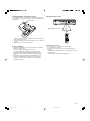
U
PHONES
STANDBY/ON
FM MODE
TUNING
SURROUND BASS MUSIC INPUT
PRESET MEMORY
VOLUME
OWNER’S MANUAL
A1-60U-1 02.8.8, 3:37 PM1

2II
• Explanation of Graphical Symbols
The lightning flash with arrowhead symbol, within
an equilateral triangle, is intended to alert you to the
presence of uninsulated “dangerous voltage” within
the product’s enclosure that may be of sufficient
magnitude to constitute a risk of electric shock to
persons.
The exclamation point within an equilateral triangle
is intended to alert you to the presence of important
operating and maintenance (servicing) instructions in
the literature accompanying the appliance.
WARNING
TO REDUCE THE RISK OF FIRE OR ELECTRIC SHOCK,
DO NOT EXPOSE THIS UNIT TO RAIN OR MOISTURE.
CAUTION
RISK OF ELECTRIC SHOCK
DO NOT OPEN
CAUTION: TO REDUCE THE RISK OF
ELECTRIC SHOCK, DO NOT REMOVE
COVER (OR BACK). NO USER-SERVICEABLE
PARTS INSIDE. REFER SERVICING TO QUALIFIED
SERVICE PERSONNEL.
1 Read Instructions – All the safety and operating instructions should be
read before the product is operated.
2 Retain Instructions – The safety and operating instructions should be
retained for future reference.
3 Heed Warnings – All warnings on the product and in the operating
instructions should be adhered to.
4 Follow Instructions – All operating and use instructions should be
followed.
5 Cleaning – Unplug this product from the wall outlet before cleaning. Do
not use liquid cleaners or aerosol cleaners. Use a damp cloth for
cleaning.
6 Attachments – Do not use attachments not recommended by the product
manufacturer as they may cause hazards.
7 Water and Moisture – Do not use this product near water – for example,
near a bath tub, wash bowl, kitchen sink, or laundry tub; in a wet
basement; or near a swimming pool; and the like.
8 Accessories – Do not place this product on an unstable cart, stand, tripod,
bracket, or table. The product may fall, causing serious injury to a child
or adult, and serious damage to the product. Use only with a cart, stand,
tripod, bracket, or table recommended by the manufacturer, or sold with
the product. Any mounting of the product should follow the
manufacturer’s instructions, and should use a mounting accessory
recommended by the manufacturer.
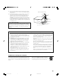
9 A product and cart combination should be moved with
care. Quick stops, excessive force, and uneven surfaces
may cause the product and cart combination to overturn.
10 Ventilation – Slots and openings in the cabinet are
provided for ventilation and to ensure reliable operation of the product
and to protect it from overheating, and these openings must not be
blocked or covered. The openings should never be blocked by placing the
product on a bed, sofa, rug, or other similar surface. This product should
not be placed in a built-in installation such as a bookcase or rack unless
proper ventilation is provided or the manufacturer’s instructions have
been adhered to.
11 Power Sources – This product should be operated only from the type of
power source indicated on the marking label. If you are not sure of the
type of power supply to your home, consult your product dealer or local
power company. For products intended to operate from battery power, or
other sources, refer to the operating instructions.
12 Grounding or Polarization – This product may be equipped with a
polarized alternating current line plug (a plug having one blade wider
than the other). This plug will fit into the power outlet only one way. This
is a safety feature. If you are unable to insert the plug fully into the
outlet, try reversing the plug. If the plug should still fail to fit, contact
your electrician to replace your obsolete outlet. Do not defeat the safety
purpose of the polarized plug.
13 Power-Cord Protection – Power-supply cords should be routed so that
they are not likely to be walked on or pinched by items placed upon or
against them, paying particular attention to cords at plugs, convenience
receptacles, and the point where they exit from the product.
14 Lightning – For added protection for this product during a lightning
storm, or when it is left unattended and unused for long periods of time,
unplug it from the wall outlet and disconnect the antenna or cable
system. This will prevent damage to the product due to lightning and
power-line surges.
15 Power Lines – An outside antenna system should not be located in the
vicinity of overhead power lines or other electric light or power circuits,
or where it can fall into such power lines or circuits. When installing an
outside antenna system, extreme care should be taken to keep from
touching such power lines or circuits as contact with them might be fatal.
16 Overloading – Do not overload wall outlets, extension cords, or integral
convenience receptacles as this can result in a risk of fire or electric
shock.
17 Object and Liquid Entry – Never push objects of any kind into this
product through openings as they may touch dangerous voltage points or
short-out parts that could result in a fire or electric shock. Never spill
liquid of any kind on the product.
18 Servicing – Do not attempt to service this product yourself as opening or
removing covers may expose you to dangerous voltage or other hazards.
Refer all servicing to qualified service personnel.
19 Damage Requiring Service – Unplug this product from the wall outlet
and refer servicing to qualified service personnel under the following
conditions:
a) When the power-supply cord or plug is damaged,
b) If liquid has been spilled, or objects have fallen into the product,
c) If the product has been exposed to rain or water,
d) If the product does not operate normally by following the operating
instructions. Adjust only those controls that are covered by the
operating instructions as an improper adjustment of other controls
may result in damage and will often require extensive work by a
qualified technician to restore the product to its normal operation,
e) If the product has been dropped or damaged in any way, and
f) When the product exhibits a distinct change in performance - this
indicates a need for service.
20 Replacement Parts – When replacement parts are required, be sure the
service technician has used replacement parts specified by the
manufacturer or have the same characteristics as the original part.
Unauthorized substitutions may result in fire, electric shock, or other
hazards.
21 Safety Check – Upon completion of any service or repairs to this
product, ask the service technician to perform safety checks to determine
that the product is in proper operating condition.
22 Wall or Ceiling Mounting – The unit should be mounted to a wall or
ceiling only as recommended by the manufacturer.
IMPORTANT SAFETY INSTRUCTIONS
A2-60U-2 (02.6.4)a 02.8.8, 3:37 PM2

3
23 Heat – The product should be situated away from heat sources such as
radiators, heat registers, stoves, or other products (including amplifiers)
that produce heat.
24 Outdoor Antenna Grounding – If an outside antenna or cable system is
connected to the product, be sure the antenna or cable system is
grounded so as to provide some protection against voltage surges and
built-up static charges. Article 810 of the National Electrical Code,
ANSI/NFPA 70, provides information with regard to proper grounding of
the mast and supporting structure, grounding of the lead-in wire to an
antenna discharge unit, size of grounding conductors, location of antenna
discharge unit, connection to grounding electrodes, and requirements for
the grounding electrode.
EXAMPLE OF ANTENNA GROUNDING
MAST
GROUND
CLAMP
ANTENNA
LEAD IN
WIRE
ANTENNA
DISCHARGE UNIT
(NEC SECTION 810–20)
GROUNDING CONDUCTORS
(NEC SECTION 810–21)
GROUND CLAMPS
POWER SERVICE GROUNDING
ELECTRODE SYSTEM
(NEC ART 250. PART H)
ELECTRIC
SERVICE
EQUIPMENT
NEC – NATIONAL ELECTRICAL CODE
1. IMPORTANT NOTICE : DO NOT MODIFY THIS UNIT!
This product, when installed as indicated in the instructions
contained in this manual, meets FCC requirements. Modifications
not expressly approved by Yamaha may void your authority, granted
by the FCC, to use the product.
2. IMPORTANT : When connecting this product to accessories and/
or another product use only high quality shielded cables. Cable/s
supplied with this product MUST be used. Follow all installation
instructions. Failure to follow instructions could void your FCC
authorization to use this product in the USA.
3. NOTE : This product has been tested and found to comply with the
requirements listed in FCC Regulations, Part 15 for Class “B”
digital devices. Compliance with these requirements provides a
reasonable level of assurance that your use of this product in a
residential environment will not result in harmful interference with
other electronic devices.
This equipment generates/uses radio frequencies and, if not
installed and used according to the instructions found in the users
manual, may cause interference harmful to the operation of other
electronic devices.
Compliance with FCC regulations does not guarantee that
interference will not occur in all installations. If this product is found
to be the source of interference, which can be determined by turning
the unit “OFF” and “ON”, please try to eliminate the problem by
using one of the following measures:
Relocate either this product or the device that is being affected by the
interference.
Utilize power outlets that are on different branch (circuit breaker or
fuse) circuits or install AC line filter/s.
In the case of radio or TV interference, relocate/reorient the antenna.
If the antenna lead-in is 300 ohm ribbon lead, change the lead-in to
coaxial type cable.
If these corrective measures do not produce satisfactory results, please
contact the local retailer authorized to distribute this type of product. If
you can not locate the appropriate retailer, please contact Yamaha
Electronics Corp., U.S.A. 6660 Orangethorpe Ave, Buena Park, CA
90620.
The above statements apply ONLY to those products distributed by
Yamaha Corporation of America or its subsidiaries.
FCC INFORMATION (for US customers)
Note to CATV system installer:
This reminder is provided to call the CATV system installer’s attention to
Article 820-40 of the NEC that provides guidelines for proper grounding
and, in particular, specifies that the cable ground shall be connected to the
grounding system of the building, as close to the point of cable entry as
practical.
YAMAHA and the Electronic Industries Association’s Consumer Electronics
Group want you to get the most out of your equipment by playing it at a safe
level. One that lets the sound come through loud and clear without annoying
blaring or distortion – and, most importantly, without affecting your sensitive
hearing.
We Want You Listening For A Lifetime
Since hearing damage from loud sounds is often undetectable
until it is too late, YAMAHA and the Electronic Industries
Association’s Consumer Electronics Group recommend you to
avoid prolonged exposure from excessive volume levels.
III
A2-60U-2 (02.6.4)a 02.8.8, 3:37 PM3

4
Manufactured under license from Dolby Laboratories.
“Dolby”, “Pro Logic”, and the double-D symbol are trademarks
of Dolby Laboratories.
“DTS” and “DTS Digital Surround” are registered trademarks of
Digital Theater Systems, Inc.
IV
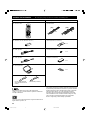
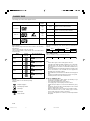
● Speaker cables
● Mounting brackets (for NX-S60S)
● Screws (for NX-S60S)
● Fasteners (for NX-S60C)
● Nonskid pads (for NX-S60S)
● Remote control
● Batteries (size AA, UM/SUM-3, R6, HP-7)
● Audio pin cable
● Video pin calbe
● AM loop antenna
● Indoor FM antenna
X 2
[5m]
[15m]
X 4 X 2
X 4
X 4
DVR-S60 NX-SW60 (NX-S60S x 4, NX-S60C, SW-S60)
This product incorporates copyright protection technology that
is protected by method claims of certain U.S. patents and other
intellectual property rights owned by Macrovision Corporation
and other rights owners. Use of this copyright protection
technology must be authorized by Macrovision Corporation,
and is intended for home and other limited viewing uses only
unless otherwise authorized by Macrovision Corporation.
Reverse engineering or disassembly is prohibited.
CHECKING THE ACCESSORIES ● Check your package to make sure it contains the following items.
X 2
(U.S.A., Canada, Australia,
China, Korean and General
models)
(U.K. and Europe models)
A2-60U-2 (02.6.4)a 02.8.8, 3:38 PM4

E-1
1 To assure the finest performance, please read this manual
carefully. Keep it in a safe place for future reference.
2 Do not install this equipment in a confined space, such as a book
case or built in cabinet.
3 Locate this system away from other electrical appliances, motors,
or transformers to avoid humming sounds. To prevent fire or
electrical shock, do not place this system where it may get exposed
to dripping or splashing, and never put any objects filled with
liquids, such as vases, on the top of the system.
4 Do not expose this system to sudden temperature changes from
cold to hot, and do not locate this system in a environment with
high humidity (i.e. a room with a humidifier) to prevent
condensation inside this system, which may cause an electrical
shock, fire, damage to this system, and/or personal injury.
5 Avoid installing this system in a place where foreign objects and
liquid might fall. It might cause a fire, damage to this system and/or
personal injury. Do not place the following objects on this system:
– Other components, as they may cause damage and/or
discoloration on the surface of this system.
– Burning objects (i.e. candles), as they may cause fire, damage to
this system, and/or personal injury.
– Containers with liquid in them, as they may cause electrical
shock to the user and/or damage to this system.
6 Do not cover this system with a newspaper, tablecloth, curtain, etc.
in order not to obstruct heat radiation. If the temperature inside this
system rises, it may cause fire, damage to this system, and/or
personal injury.
7 Do not plug in this system to a wall outlet until all connections are
complete.
8 Do not operate this system upside-down. It may overheat, possibly
causing damage.
9 Do not use force on switches, knobs and/or cables.
10 When disconnecting the power cable from the wall outlet, grasp the
plug; do not pull the cable.
11 Do not clean this system with chemical solvents; this might damage
the finish. Use a clean, dry cloth.
12 Only voltage specified on this system must be used. Using this
system with a higher voltage than specified is dangerous and may
cause fire, damage to this system, and/or personal injury. YAMAHA
will not be held responsible for any damage resulting from use of
this system with a voltage other than specified.
13 To prevent damage by lightning, disconnect the power cable from
the wall outlet during an electrical storm.
14 Take care of this system so that no foreign objects and/or liquid
drops inside this system.
15 Do not attempt to modify or fix this system. Contact qualified
YAMAHA service personnel when any service is needed. The
cabinet should never be opened for any reasons.
16 When not planning to use this system for long periods of time (i.e.
vacation), disconnect the AC power plug from the wall outlet.
17 Be sure to read the “TROUBLESHOOTING GUIDE” section on
common operating errors before concluding that this system is
faulty.
18 Before moving this system, press STANDBY/ON to set this system
in the standby mode, and disconnect the AC power plug from the
wall outlet.
19 VOLTAGE SELECTOR (General model only)
The VOLTAGE SELECTOR on the rear panel of DVR-S60 must be
set for your local main voltage BEFORE plugging into the AC main
supply.
Voltages are 110–120V/220–240V AC, 50/60 Hz.
This system is not disconnected from the AC power source as long
as it is connected to the wall outlet, even if this system itself is
turned off. This state is called the standby mode. In this state, this
system is designed to consume a very small quantity of power.
IMPORTANT
Please record the serial number of DVR-S60 in the space below.
MODEL:
Serial No.:
The serial number is located on the rear of DVR-S60.
Retain this Owner’s Manual in a safe place for future reference.
FOR CANADIAN CUSTOMERS
To prevent electric shock, match wide blade of plug to wide slot and
fully insert.
This Class B digital apparatus complies with Canadian ICES-003.
■ For U.K. customers
If the socket outlets in the home are not suitable for the plug supplied
with this appliance, it should be cut off and an appropriate 3 pin plug
fitted. For details, refer to the instructions described below.
Note
• The plug severed from the mains lead must be destroyed, as a plug
with bared flexible cord is hazardous if engaged in a live socket
outlet.
■ Special Instructions for U.K. Model
IMPORTANT
THE WIRES IN MAINS LEAD ARE COLOURED IN ACCORDANCE
WITH THE FOLLOWING CODE:
Blue: NEUTRAL
Brown: LIVE
As the colours of the wires in the mains lead of this apparatus may
not correspond with the coloured markings identifying the terminals
in your plug, proceed as follows:
The wire which is coloured BLUE must be connected to the terminal
which is marked with the letter N or coloured BLACK. The wire
which is coloured BROWN must be connected to the terminal which
is marked with the letter L or coloured RED.
Making sure that neither core is connected to the earth terminal of
the three pin plug.
DANGER
Visible laser radiation when open. Avoid direct exposure to beam.
When this system is plugged to the wall outlet, do not place your eyes
close to the opening of the disc tray and other openings to look into
inside.
The laser component in this product is capable of emitting radiation
exceeding the limit for Class 1.
CAUTION: READ THIS BEFORE OPERATING YOUR SYSTEM.
A3-60U-E (02.7.26)a 02.8.8, 3:38 PM1

E-2
IMPORTANT SAFETY INSTRUCTIONS....................... II
CHECKING THE ACCESSORIES ............................... IV
CAUTION ....................................................................... 1
CONTROLS ................................................................... 3
Front panel ......................................................................... 3
Display ................................................................................ 3
REMOTE CONTROL ..................................................... 4
Controls .............................................................................. 4
Installing batteries in the remote control ............................. 5
Using the remote control .................................................... 5
SPEAKER PLACEMENT ............................................... 6
Placing the speakers .......................................................... 6
Placing the center speaker ................................................. 6
Mounting the front and surround speakers ......................... 7
BASIC CONNECTIONS ................................................. 8
Speaker connections .......................................................... 8
Antenna connections .......................................................... 9
Connecting to a TV with the video pin cable ...................... 9
ADDITIONAL CONNECTION EXAMPLES .................. 10
Connecting to a TV with an S video cable ........................ 10
Connecting to a TV with a component video cable .......... 10
VCR connections .............................................................. 10
Progressive-scan TV connections .................................... 11
Headphones ..................................................................... 11
BASIC OPERATION..................................................... 12
Turning the power on and off ............................................ 12
Direct start function .......................................................... 12
Selecting the source ......................................................... 12
Adjusting the volume ........................................................ 12
To reduce the volume temporarily .................................... 12
Bass extension ................................................................. 12
Selecting the sound mode ................................................ 12
What to do if ... ................................................................. 12
ADJUSTING THE CLOCK ........................................... 12
SELECTING THE SURROUND MODE ....................... 13
Selecting Dolby Pro Logic mode ...................................... 13
PLAYABLE DISCS ....................................................... 14
DISC PLAY ................................................................... 15
Preparations ..................................................................... 15
Loading a disc .................................................................. 15
Starting play ..................................................................... 15
Stopping play .................................................................... 15
SETTINGS ON THE SET UP MENU ........................... 16
Common procedures of settings ...................................... 16
Language .................................................................... 16
Display ........................................................................ 16
Speaker....................................................................... 17
Parental ....................................................................... 17
VARIOUS DISC PLAYING FUNCTIONS ..................... 18
Selecting a DVD menu [DVD] ........................................... 18
Selecting a title menu [DVD] ............................................. 18
Return button (RETURN) [Video CD] ............................... 18
Chapter (Track) skip ......................................................... 18
Title search [DVD]............................................................. 18
Chapter search [DVD] ...................................................... 18
Track search [Video CD] [CD]........................................... 18
Time search ...................................................................... 18
Fast play ........................................................................... 18
Slow-motion play .............................................................. 18
Still picture (Pause) .......................................................... 18
Frame by frame advance play [DVD] [Video CD] ................ 18
Picture zoom [DVD] [Video CD] ........................................ 19
Viewing from a desired camera angle
(Multi-Angle) [DVD] .......................................................... 19
Angle replay [DVD] ........................................................... 19
Repeat play ...................................................................... 19
Programmed play [Video CD] [CD] ................................... 19
Selecting subtitle language [DVD] .................................... 20
Selecting audio soundtrack language
(Multi-Language) [DVD] .................................................... 20
Changing the audio channel output [Video CD] .............. 20
Selecting on-screen information ....................................... 20
MP3 CD OPERATION .................................................. 21
MP3 CD information ......................................................... 21
MP3 CD play .................................................................... 21
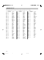
LANGUAGE CODE LIST ............................................. 22
LISTENING TO VIDEO SOURCES.............................. 23
LISTENING TO THE RADIO ........................................ 23
Automatic/Manual tuning .................................................. 23
To preset stations ............................................................. 23
Listening to preset stations............................................... 23
To receive FM stereo broadcasts ..................................... 23
TIMER OPERATION .................................................... 24
Using the timer ................................................................. 24
Using the sleep timer ........................................................ 24
TROUBLESHOOTING GUIDE ..................................... 25
SPECIFICATIONS........................................................ 26
CONTENTS
A3-60U-E (02.7.26)a 02.8.8, 3:38 PM2

E-3
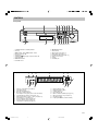
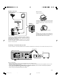
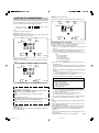
1. STANDBY/ON button, Standby indicator
2. Disc tray
3. f/TUNING – button, e/TUNING + button
4. Open/Close button (q)
5. Play button (
)
6. FM MODE button [see page 23.]/Pause button (k)
7. Stop button (n)
8. d/PRESET button
9. VOLUME control
C
T
DOLBY DIGITAL
DOLBY
PL DTS
ST MONO
kHz
PROG. ALL 1
MHz
REP.
SLEEP
ON OFF
1 2 5 6
8
9
151618 10
111417
1213
7
3 4
CONTROLS
Display
11. Kilohertz indicator (kHz)
12. Megahertz indicator (MHz)
13. Chapter indicator (C)
14. Pause indicator (k)
15. FM mono indicator (MONO) [see page 23.]
16. FM stereo indicator (ST) [see page 23.]
17. Play indicator ( )
18. Dolby Digital indicator (DOLBY DIGITAL)
1. Dolby Pro Logic indicator (DOLBY PL)
2. DTS indicator (DTS)
3. Title and Track indicator (T)
4. Message or number indicators
(Title, chapter, track, playing time or other information)
5. Program indicator (PROG.) [see page 19, 23.]
6. Repeat mode indicators (ALL, 1, REP.) [see page 19.]
7. Timer indicator (0) [see page 24.]
8. Timer off indicator (OFF) [see page 24.]
9. Timer on indicator (ON) [see page 24.]
10. Sleep indicator (SLEEP) [see page 24.]
10. c/MEMORY button
11. INPUT button
12. MUSIC button [see page 12.]
13. BASS button [see page 12.]
14. SURROUND button [see page 13.]
15. Remote control sensor
16. Display
17. PHONES jack
PHONES
STANDBY/ON
FM MODE
TUNING
SURROUND BASS MUSIC INPUT
PRESET MEMORY
VOLUME
1 2 384 5 6 7 9
1011121314151617
Front panel
A3-60U-E (02.7.26)a 02.8.8, 3:38 PM3

E-4
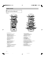
REMOTE CONTROL
6. Open/Close (q) button
7. SET/CLEAR button [see page 24.]/
CANCEL button [see page 18, 19.]
8. LEVEL button [see page 13.]
9. MENU button [see page 18.]
10. ENTER button
11. RETURN button [see page 18.]
12. Play button (
)
13. Stop button (n)
14. SKIP f/ e buttons
15. AUDIO button [see page 20.]
16. SUBTITLE button [see page 20.]
17. REPEAT button [see page 19.]
18. Last memory button (LAST MEMO) [see page 15.]
19. PROGRAM button [see page 19.]
20. SEARCH MODE button [see page 18.]
21. SLOW
/ buttons [see page 18.]
22. SEARCH d/ c buttons
23. Pause button (k)
24. ON SCREEN button [see page 20.]
25. 4, a, 5, b buttons
26. TITLE button [see page 18.]
27. SET UP button [see page 16.]
1 2 3 4
5 6 7 8
9 0
10
CANCEL
SET UP
ANGLE REPLAY ZOOM
SLEEP TIMER ADJUST
CLOCK
FM MODE
BASS TEST LEVEL TUNER
MUTE
SURROUND
MUSIC
VOLUME
TITLE
ON SCREEN
SEARCH
SEARCH MODE PROGRAM LAST MEMO REPEAT
SLOW AUDIO
SUBTITLE
SKIP
RETURN
ENTER
MENU
INPUT
TUNING PRESET
SET/CLEAR
SHIFT
POWER
5
4
1
2
3
1 2 3 4
5 6 7 8
9 0
10
CANCEL
SET UP
ANGLE REPLAY ZOOM
SLEEP TIMER ADJUST
CLOCK
FM MODE
BASS TEST LEVEL TUNER
MUTE
SURROUND
MUSIC
VOLUME
TITLE
ON SCREEN
SEARCH
SEARCH MODE PROGRAM LAST MEMO REPEAT
SLOW AUDIO
SUBTITLE
SKIP
RETURN
ENTER
MENU
INPUT
TUNING PRESET
SET/CLEAR
SHIFT
POWER
27
26
25
6
7
8
9
24
23
20
22
11
13
15
14
16
17
18
10
12
21
19
Note:
In this instruction manual, any operation of pressing a button while
pressing the SHIFT button is described as follows.
Example: “Press SHIFT + 2 ANGLE buttons.”
Controls
1. POWER button (z/I)
2. Number and other function buttons
Number buttons (1–9, 0,
≥10)
ANGLE button [see page 19.]
ANGLE–REPLAY button [see page 19.]
ZOOM button [see page 19.]
SLEEP button [see page 24.]
TIMER button [see page 24.]
ADJUST button [see page 12.]
CLOCK button [see page 12.]
3. Amplifier controls
INPUT button
TEST tone [see page 13.]
SURROUND button [see page 13.]
BASS button [see page 12.]
MUSIC button [see page 12.]
MUTE button [see page 12.]
VOLUME –/+ buttons
4. Tuner controls
TUNER button (Tuner/Band select button)
PRESET button (Preset tuning button)
[see page 23.]
TUNING –/+ buttons [see page 23.]
FM MODE button [see page 23.]
5. SHIFT button
A3-60U-E (02.7.26)a 02.8.8, 3:38 PM4

E-5
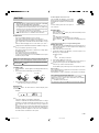
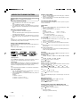
Using the remote control
Handling the remote control
• Do not spill water or other liquids on the remote control.
• Do not drop the remote control.
• Do not leave or store the remote control in the following types of
conditions:
– high humidity or temperature such as near a heater, stove or bath;
– dusty places; or
– in places subject to extremely low temperatures.
Installing batteries in the remote control
Insert the batteries in the correct direction by aligning the + and – marks
on the batteries with the polarity markings (+ and –) inside the battery
compartment.
1. Press the tab on the battery compartment cover in the direction of the
arrow and remove the cover.
2. Insert the two batteries (AA, R06, UM-3 type) with + and – oriented
properly.
3. Attach the cover so that it snaps into place.
Notes on batteries
• Change all of the batteries if you notice a decrease in the operating
range of the remote control.
• Do not use old batteries together with new ones.
• Do not use different types of batteries (such as alkaline and
manganese batteries) together. Read the packaging carefully as
these different types of batteries may have the same shape and
color.
• If the batteries have leaked, dispose of them immediately. Avoid
touching the leaked material or letting it come into contact with
clothing, etc. Clean the battery compartment thoroughly before
installing new batteries.
1
3
2
PHONES
STANDBY/ON
FM MODE
TUNING
SURROUND BASS MUSIC INPUT
PRESET MEMORY
VOLUME
Approximately 6 m (20 feet)
30⬚
30⬚
Press the tab.
A3-60U-E (02.7.26)a 02.8.8, 3:38 PM5

E-6
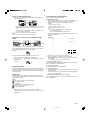
SPEAKER PLACEMENT
Before making connections, place all speakers in their respective positions. The positioning of the speakers is important because it controls the whole
sound quality of this system.
Place the speakers depending on your listening position by following the instructions below.
Note:
- In this speaker package, the same speakers (NX-S60S) are used for the front and surround speakers.
- Although the speaker system in this system is magnetically shielded, it may still affect the color on the television monitor when using this system
near the television. Adjust the relative positions of this system and the television if this happens.
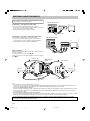
Placing the speakers
Front speakers: On both sides of and at approximately
the same height as the TV set.
Surround speakers:
Behind your listening position, facing
slightly inward. About 1.8 m (approx.
6 feet) from the floor.
Center speaker: Precisely between the front speakers.
Subwoofer: The position of the subwoofer is not
so critical because low bass tones are
not highly directional.
QD-Bass Technology
QD-Bass (Quatre Dispersion Bass) technology uses
square, pyramid-shaped reflective plates to radiate the
sound in four horizontal directions.
Caution for carrying the subwoofer
Do not insert your hands
into the openings at the
lower part of the subwoofer
when carrying it.
If you touch the inside
speaker unit, it may be
damaged.
Remove the warning label
put by the factory setting
when using the subwoofer.
Surround right speaker
Surround left speaker
Subwoofer
Front right speaker
Front left
speaker
Center speaker
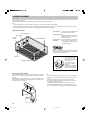
Placing the center speaker
You can place the speaker on top of the TV if the top is flat, on the floor
under the TV, or inside the TV rack . Be sure to place the speaker in a stable
position.
When placing the speaker on top of the TV, to prevent the speaker from
falling, attach the provided fasteners at two points on the bottom of the
speaker and on the top of the TV.
Note:
- Do not place the speaker on top of a TV whose area is smaller than
the bottom of the speaker. If placed, the speaker may fall and cause
injury.
- Do not place the speaker on top of a TV if the top is inclined.
- Do not touch the adhesive surface after peeling off the seal as this
will weaken its adhesive strength.
- Thoroughly wipe clean the surface where the fastener is to be
applied. Note that adhesive strength is weakened if the surface is
dirty, oily or wet and that this may cause the center speaker to drop.
Peel off
the seal
Fastener
A3-60U-E (02.7.26)a 02.8.8, 3:38 PM6

E-7
Mounting the front and surround speakers
Mount the speakers on a shelf, rack or directly on the floor, or hang them
on the wall.
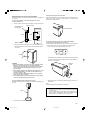
To mount the speakers on a wall by using the holes on the
speakers’ back panels
1. Fasten screws into a firm wall or wall support as shown in the figure.
2. Hang the speaker by mounting the holes on the protruding screws.
* Make sure that the screws are securely caught by the narrow parts
of the holes.
WARNING
● Each speaker weighs 0.9 kg (2 lbs.). Do not mount them on thin
plywood or a wall composed of a soft surface material. If
mounted, the screws may pull out of the flimsy surface and the
speakers may fall. This may damage the speakers or cause
personal injury.
● Do not affix the speakers to a wall using nails, adhesives, or any
other unstable hardware. Long-term use and vibrations may
cause the speakers to fall.
● To avoid accidents resulting from tripping over loose speaker
cables, fix the cables to the wall.
● Select an appropriate position on the wall to mount the speaker
so that no one will injure his/her head or face.
Using the Yamaha Speaker Stand SPS-80 (option)
By using the Yamaha Speaker Stand SPS-80, speakers can be placed on
the floor.
* The SPS-80 is not available in some areas.
Wall/ wall support
Min.
20 mm
Diam. 3.5–4 mm
10 mm
70 mm
70 mm
70 mm
Round head screw
(not supplied)
SPS-80
Placing the the front/surround speakers
When placing the speakers on a flat surface, attach the included nonskid
pads to the corners on the bottom of the speakers. This prevents the
speakers from sliding around.
If you want to mount a speaker on a commercially available
speaker stand for the front/surround speakers
The provided mounting bracket with 1 pair of screw holes (at an interval
of 60 mm) can be used to mount the speaker on a speaker stand.
* Those screw holes can be used with M4 screws only.
1. Attach the bracket to the bottom of the speaker by using the provided
screw so that the convex part of the bracket fits in the grooved part on
the bottom of the speaker.
2. Mount the speaker on the speaker stand by using the screw holes on
the bracket.
Note:
The mounting bracket is provided for each speaker.
Note:
- Be careful not to let the speaker system fall, it might cause damage
or serious injuries.
- If you use another speaker system, please change the settings of
“Speaker” under “SETTINGS ON THE SET UP MENU” to the
proper settings for the speaker system. (See Page 17.)
Mounting
bracket
Screw
Nonskid pads
60 mm
A3-60U-E (02.7.26)a 02.8.8, 3:38 PM7

E-8
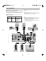
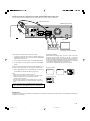
Speaker connections
Be sure all connections are made correctly, that is to say, L (left) to L, R
(right) to R, “+” to “+” and “–” to “–”.
Label of the Color tube Use
speaker cable
FRONT R Red Front right speaker
FRONT L White Front left speaker
CENTER Green Center speaker
REAR R Gray Surround right speaker
REAR L Blue Surround left speaker
SUBWOOFER Purple Subwoofer
BASIC CONNECTIONS
Selecting TV system (for General model only)
Before connecting, set the TV SYSTEM switch (rear of the unit) to the
position of your local TV system (PAL or NTSC).
After all connections have been made, connect the power cable to
an AC outlet.
Note:
- Do not connect the power cable to an AC outlet until all connections
have been made.
- The system is not completely disconnected from the AC outlet when
the STANDBY/ON button is set to the standby mode.
VIDEO
S-VIDEO
(
DVD ONLY
)
MONITOR OUT
LR LR
SPEAKERS
8
Ω
CENTERFRONT
SUB
WOOFER
REAR
SURROUND
VIDEO 1 VIDEO 2
VIDEO
AUDIO
IN OUT
IN
IN
INOUT
L
R
L
R
VIDEO OUT SELECT
(
DVD ONLY
)
VIDEO OUT
SCAN SELECT
S-VIDEOCOMPONENT
COMPONENT
VIDEO OUT
480
p
/480i
(
DVD ONLY
)
Y
P
B
PR
SELECTABLE INTERLACE
480
p
/480i 480i
(
DVD ONLY
)
FRONT R
FRONT L
CENTER
REAR R
REAR L SUBWOOFER
Front right speaker
Front left speaker
Center speaker
Surround right speaker Surround left speaker Subwoofer
White
Green
Gray
Purple
DVR-S60 (U.S.A. model)
Red
Black Red
Blue
Black Red
Black Red
Black Red Black Red
Note:
• The label of the speaker is attached to each speaker cable. Connect
the speakers in accordance with the labels.
• Connect the color tube of the speaker cable to the plus (+) side of
each speaker. If the polarity of the speaker connections is incorrect,
the sound will be unnatural and lack bass.
• A cover is attached to the end of the speaker cable. Connect the
speakers after removing the cover.
Red White
Green
Gray
Blue
Purple
Black Red
A3-60U-E (02.7.26)a 02.8.8, 3:38 PM8

E-9
Antenna connections
In areas close to a transmitter the simple indoor antenna is sufficient to
receive broadcasts. Extend the antenna wire as straight as possible and,
while listening to the sound from the system, secure it in a position which
yields minimal distortion and noise.
In fringe areas or where reception is distorted or noisy, an external
antenna (not supplied) should be connected instead of the simple indoor
antenna. Consult your dealer.
DVR-S60
TUNER
FM
ANT
AM
ANT
VIDEO 1
VIDEO
AUDIO
IN OUT
IN OUT
L
R
75
Ω
GND
FM
ANT
AM
ANT
75
Ω
GND
Indoor FM antenna
Outdoor FM antenna
(not supplied)
AM loop antenna
AM loop antenna
Set up the loop antenna.
Unwind the antenna wires, then connect them to the AM
ANT terminals. Place the loop antenna in a position which
yields the best AM reception, or attach it to a wall or other
surface.
Note:
To minimize noise, the speakers, power cable and any
other cable should not come close to the indoor or
external antenna cable and AM loop antenna . Do not
place the antenna cables close to the system.
Connecting to a TV with the video pin cable
Connect the included or commercially available video pin cable between the MONITOR OUT VIDEO jack of the unit and the video input jack of the TV.
Notes on connections
- Please refer to the instruction manuals for the components that you are connecting (TV, etc.).
- When you connect the unit to your TV and other equipment, be sure to turn off the power and disconnect all of the equipments from the AC outlet
until all the connections have been made.
- Do not connect the MONITOR OUT (S VIDEO/VIDEO) and COMPONENT VIDEO OUT jacks of the unit to a VCR directly. The playback
picture will be distorted because DVD discs are copy protected.
- Please consult your local audio/video dealer for more details.
1
2
1
2
3
Screws (not supplied)
VIDEO
S-VIDEO
(
DVD ONLY
)
MONITOR OUT
LR LR
SPEAKERS
8
Ω
CENTERFRONT
SUB
WOOFER
SURROUND
TUNER
FM
ANT
AM
ANT
VIDEO 1 VIDEO 2
VIDEO
AUDIO
IN OUT
IN
IN
INOUT
L
R
L
R
75
Ω
GND
VIDEO OUT SELECT
(
DVD ONLY
)
VIDEO OUT
SCAN SELECT
S-VIDEOCOMPONENT
COMPONENT
VIDEO OUT
480
p
/480i
(
DVD ONLY
)
Y
P
B
P
R
SELECTABLE INTERLACE
U.C
(
US.CA
)
MADE IN CHINA
R-AUDIO-L VIDEO
AUDIO
VIDEO
INPUT
1
480
p
/480i 480i
(
DVD ONLY
)
DVR-S60 (U.S.A. model)
TV
Video pin cable
DVR-S60
(U.S.A. model)
A3-60U-E (02.7.26)a 02.8.8, 3:38 PM9

E-10
ADDITIONAL CONNECTION EXAMPLES
For connections, use the included or commercially available connection
cables suitable for respective connections.
Connecting to a TV with an S video cable
Please follow the steps below before turning on the power.
1. If your TV has an S video input jack, connect the unit as shown in the
figure. You can enjoy clearer picture playback.
2. Set the VIDEO OUT SELECT switch to S VIDEO.
Connecting to a TV with a component video cable
Please follow the steps below before turning on the power.
1. If your TV has component video input jacks, connect the unit as
shown in the figure. You can enjoy high quality picture playback.
2. Set the VIDEO OUT SELECT switch to COMPONENT.
VCR connections
With this connection, it is possible to watch and listen to videocassettes or
other video equipment.
Connect the 1st VCR as shown in figure 1–4.
If using the 2nd VCR or other video equipment, connect it as shown in
figure 5–6.
VIDEO
S-VIDEO
(
DVD ONLY
)
MONITOR OUT
LR LR
SPEAKERS
8
Ω
CENTERFRONT
SUB
WOOFER
SURROUND
L
R
VIDEO OUT
SCAN SELECT
S-VIDEOCOMPONENT
COMPONENT
VIDEO OUT
480
p
/480i
(
DVD ONLY
)
Y
P
B
PR
SELECTABLE INTERLACE
U
MAD
COMPONENT VIDEO INPUT
YCBCR
480
p
/480i 480i
(
DVD ONLY
)
VIDEO OUT SELECT
(
DVD ONLY
)
2
1
DVR-S60 (U.S.A. model)
DVR-S60 (U.S.A. model)
TV
VIDEO
S-VIDEO
(
DVD ONLY
)
MONITOR OUT
LR LR
SPEAKERS
8
Ω
CENTERFRONT
SUB
WOOFER
SURROUND
VIDEO OUT
SCAN SELECT
SELECTABLE INTERLACE
U.C
(
U
MADE IN
S-VIDEO
IN 1
480
p
/480i 480i
(
DVD ONLY
)
S-VIDEOCOMPONENT
VIDEO OUT SELECT
(
DVD ONLY
)
1
2
S Video cable
Component video cable
TV
VIDEO
S-VIDEO
(
DVD ONLY
)
MONITOR OUT
LR LR
SPEAKERS
8
Ω
CENTERFRONT
SUB
WOOFER
SURROUND
TUNER
FM
ANT
AM
ANT
VIDEO 1 VIDEO 2
VIDEO
AUDIO
IN OUT
IN
IN
INOUT
L
R
L
R
75Ω
GND
VIDEO OUT SELECT
(
DVD ONLY
)
VIDEO OUT
SCAN SELECT
S-VIDEOCOMPONENT
COMPONENT
VIDEO OUT
480
p
480i
(
DVD ONLY
)
Y
P
B
PR
SELECTABLE INTERLACE
VHF/UHF
FROM ANT.
IN
OUT
TO TV
IN OUT
34
LINE1(AUX1)
VIDEO
CH.
L
R
L
R
AUDIO
VHF/UHF
FROM ANT.
IN
OUT
TO TV
IN OUT
34
LINE1(AUX1)
VIDEO
CH.
L
R
L
R
AUDIO
1
2
3
4
5
6
VCR (1st)
VCR (2nd)
DVR-S60 (U.S.A.
model)
Video pin cable
Audio pin
cable
Note:
- The picture from the VCR may be distorted in some cases.
- If you use the VCR, you must connect the video pin cable between the MONITOR OUT VIDEO jack of the unit and the video input jack of the TV.
There are no VCR video signals from the MONITOR OUT S VIDEO and COMPONENT VIDEO OUT jacks of the unit.
-
<For U.S.A., Canada and Korean models>
Be sure to check and/or change the settings of the VIDEO OUT SELECT and VIDEO OUT SCAN SELECT switches before turning on this system.
If the setting of either or both switches is changed during play, picture may be disturbed or disappear from the monitor. In such a case, turn this
system off and then on again.
<For U.K., Europe, Australia, China and General models>
Be sure to check and/or change the setting of the VIDEO OUT SELECT switch before turning on this system. If the setting of this switch is changed
during play, picture may be disturbed or disappear from the monitor. In such a case, turn this system off and then on again.
Do not connect this system to a TV through a VCR. If you do so, the picture may not be played back properly due to the copyright
protection technology incorporated in this system.
Video pin cable
Audio pin
cable
Video pin
cable
Audio pin
cable
A3-60U-E (02.7.26)a 02.8.8, 3:38 PM10

E-11
VIDEO
S-VIDEO
(
DVD ONLY
)
MONITOR OUT
LR LR
SPEAKERS
8
Ω
CENTERFRONT
SUB
WOOFER
TUNER
FM
ANT
AM
ANT
VIDEO 1 VIDEO 2
VIDEO
AUDIO
IN OUT
IN
IN
INOUT
L
R
L
R
75Ω
GND
S-VIDEOCOMPONENT
COMPONENT
VIDEO OUT
480
p
/480i
(
DVD ONLY
)
Y
P
B
PR
U.C
(
US.CA
)
MADE IN CHINA
COMPONENT VIDEO INPUT
YC
B
/P
B
C
R
/P
R
REAR
SURROUND
VIDEO OUT SELECT
(
DVD ONLY
)
VIDEO OUT
SCAN SELECT
SELECTABLE INTERLACE
480
p
/480i 480i
(
DVD ONLY
)
2
3
1
+
Please follow the steps below before turning on the power.
1. Connect the component video cable (not supplied) between the
COMPONENT VIDEO OUT jacks of the unit and the COMPONENT
VIDEO INPUT jacks of the TV.
2. Set the VIDEO OUT SELECT switch to the COMPONENT position.
3. Set the VIDEO OUT SCAN SELECT switch to the SELECTABLE
position.
After all connections and settings on the rear panel are completed, turn on
the power of this system and the TV, then make the following setting.
4. Select “COMPONENT OUTPUT: PROGRESSIVE” in “Display” on
the SETTINGS ON THE SET UP MENU. (See page 16.)
Notes:
• Please refer to the instruction manual of your TV.
• When you connect the unit to your TV, be sure to turn off the power
and disconnect both units from the wall outlet until all the
connections have been made.
• After the above connections have been made, there are no video
signals from the MONITOR OUT VIDEO and VIDEO 1 VIDEO OUT
jacks.
Do not connect the unit to a VCR directly. The playback picture
will be distorted because DVD video discs are copy protected.
Component video cable
Green
Red
Blue
TV with progressive-scan capability
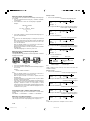
Progressive-scan TV connections (for U.S.A., Canada and Korean models only)
To AC outlet
Your TV must be capable of handling progressive scanning and have component video input capability.
Progressive Scanning
While interlaced scanning produces one frame of video in two fields,
progressive scanning creates one frame in one field. Conventional
interlaced scanning constitutes one second with 30 frames (60 fields), but
progressive scanning constitutes it with 60 frames from scratch. Progressive
scanning can reproduce sharper picture with high resolution for still image
or other picture containing long texts or horizontal lines.
This model has compliance with 480p (progressive) system.
Interlaced scanning
Progressive scanning
Green
Red
Blue
Headphones
Connect stereo headphones (not supplied) to the PHONES jack for monitoring or for private listening. The speakers are automatically disconnected when
headphones are connected.
DVR-S60 (U.S.A. model)
A3-60U-E (02.7.26)a 02.8.8, 3:38 PM11

E-12
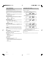
BASIC OPERATION
Turning the power on and off
Press the STANDBY/ON button. The STANDBY indicator goes out. (After
connecting the power cable, when you press the STANDBY/ON button for
the first time, the volume-reset feature automatically sets the initial volume
level.)
To turn the power off, press the STANDBY/ON button again. The STANDBY
indicator lights up.
- When the power cable is connected to the AC outlet, the unit can be
controlled from the remote control.
Direct start function
If the following buttons are pressed when the unit is in the standby mode,
the unit turns on automatically and the selected source is activated.
Main unit
, q
Remote control
, TUNER, q
Selecting the source
Press the INPUT button to select the desired source. Each time the button
is pressed, the display changes as follows:
DVD
v
VIDEO 1
v
VIDEO 2
v
FM
v
AM
v
. . .
- When the source selection is changed, disc play is automatically
stopped.
Adjusting the volume
Turn the VOLUME control (or press the + or – VOLUME button on the
remote control). The volume level appears on the display (VOL 0 – VOL
39, MAX).
To reduce the volume temporarily (using the remote
control)
Press the MUTE button. The “MUTE” indicator flashes on the front panel
display. To restore the previous volume setting, press the MUTE button
again.
Bass extension
Press the BASS button to select the desired bass boost effect.
BASS OFF
v
BASS ON1
v
BASS ON2
v
BASS OFF . . .
Selecting the sound mode
Press the MUSIC button to select the sound mode matching the source to
be listened to.
POP: Pops, etc.
CLASSIC: Classical music, etc.
ROCK: Rock music, etc.
JAZZ: Jazz, etc.
What to do if...
If the operation of the unit or display is not normal,
1. Disconnect the power cable.
2. While pressing both BASS and MUSIC buttons on the main unit at the
same time, connect the power cable. “RESET” briefly appears on the
display.
3. Resume operation.
ADJUSTING THE CLOCK
(Using the remote control)
Example: To set “PM 6:30”
1. Press the STANDBY/ON button to turn the power on.
2. Press the SHIFT + 0 CLOCK buttons. “AM 12:00” flashes.
3. Press the SHIFT + 8 ADJUST buttons.
The hour display flashes.
4. Press the TUNING – or + button to set the “hours”.
5. Press the SHIFT + 8 ADJUST buttons.
The minute display flashes.
6. Press the TUNING – or + button to set the “minutes”.
7. Press the SHIFT + 8 ADJUST buttons. The clock starts.
- The time can be set accurately by pressing the SHIFT + 8
ADJUST buttons when a time signal is heard.
To display the clock during operation
Press the SHIFT + 0 CLOCK buttons. Press both buttons again to return
to the original display.
Note:
When the display flashes because of a power failure, reset the time.
A3-60U-E (02.7.26)a 02.8.8, 3:38 PM12

E-13
SELECTING THE SURROUND MODE
Press the SURROUND button to select the surround mode. Each time the
button is pressed, the surround mode changes as follows:
DOLBY PL
v
DOLBY 3
v
DOLBY D
v
DTS
v
THEATER
v
HALL
v
SURR OFF
v
DOLBY PL . . .
Note:
Some discs may restrict the selection.
DOLBY PL: Dolby Pro Logic mode
When playing a program source encoded with Dolby Surround sound
(video tape, laser disc, DVD, etc.) (Fig. A)
DOLBY 3: 3 channel mode
Using only the Front left, Center, Front right and Subwoofer speakers
(Fig. B)
DOLBY D:
Dolby Digital 5.1 Channel mode
When DVD disc encoded with Dolby Digital 5.1 Channel is played
back, you can select “DOLBY D”. (Fig. A)
Note:
Center or Surround speakers do not sound with some discs.
DTS:
DTS Digital Surround mode
When DVD disc encoded with DTS Digital Surround System
(5.1ch) is played back, you can select “DTS”. (Fig. A)
Note:
Center or Surround speakers do not sound with some discs.
THEATER: “Theater” effect
HALL: “Hall” effect
When playing a program source which is not encoded with Dolby Surround
or DTS sound (Fig. A)
SURR OFF: Normal stereo sound
Using only the Front left, Front right and Subwoofer speakers (Fig. C)
Selecting Dolby Pro Logic mode
If you play a program source encoded with Dolby Surround or DTS sound
(video tape, laser disc, DVD etc.), follow the steps below.
Please use the remote control at the listening position.
1. Press the + or – VOLUME button to adjust the sound level from the
speakers.
2. Press the SURROUND button repeatedly until “DOLBY PL” appears.
3. Press the TEST button. “TTONE” appears and “FL” flashes.
The test tone will be heard from each speaker sequentially as follows:
TTONE
FL (Front left speaker)
C (Center speaker)
FR (Front right speaker)
RS (Surround right speaker)
LS (Surround left speaker)
4. Press the + or – VOLUME button until the test tone turns into a
comfortable level.
If the test tone level is not the same from each speaker, you may need
fine adjustment of the volume level. Please follow the steps as below.
Note:
If you make no operation, the original display returns after approximately
a minute.
1) Press the TEST button to turn the test tone off.
2)
Press the SURROUND button to select the desired surround mode.
3) Press the LEVEL button. “FNTL 0” appears.
4) Press the ENTER button repeatedly to select the speaker.
Display (Speaker)
FNTL (Front left speaker)
CENT (Center speaker)
FNTR (Front right speaker)
SURR (Surround right speaker)
SURL (Surround left speaker)
SUBW (Subwoofer)
5) Press the a or b button to adjust the volume level. (FNTL/FNTR:
“0” to “–10”, CENT/SURR/SURL/SUBW: “+10” to “–10”.)
6) Press the ENTER button.
7) Repeat step 4) to 6) for another speaker, if necessary.
8) Press the LEVEL button again to turn it off.
5. Press the TEST button to turn the test tone off. “TTONE” disappears.
6. Press the + or – VOLUME button to adjust the volume.
Notes:
- There is no Dolby Surround effect when monaural program material
is used.
- When receiving weak FM broadcasts, switch the Dolby Pro Logic off.
The sound quality may improve.
- When headphones are connected while any of the surround modes
are selected, the surround mode is switched off automatically. The
SURROUND button does not function while headphones are
connected.
- For other surround mode, please refer to “Selecting Dolby Pro Logic
mode” as above.
- This adjustment can be set at each source individually.
Surround
right
speaker
Surround
left
speaker
Subwoofer
Front
right
speaker
Front
left
speaker
Center
speaker
Fig. A
Fig. B
Surround
right
speaker
Surround
left
speaker
Subwoofer
Front
right
speaker
Front
left
speaker
Center
speaker
Surround
right
speaker
Surround
left
speaker
Subwoofer
Front
right
speaker
Front
left
speaker
Center
speaker
Fig. C
A3-60U-E (02.7.26)a 02.8.8, 3:38 PM13

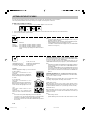
E-14
Region number
Region number (Regional restriction code) is built-in to the DVD player
and DVD discs.
There is a region number on the rear of the unit.
The same region number or region number “ALL” of DVD discs can be
used on this unit.
DVD disc
There are marks on some DVD disc package.
Examples:
Multiple Languages
Multi-language subtitles
Multi-Angle
Multi-Aspect
Region number
PLAYABLE DISCS
The following types of discs can be played on this unit.
3
2
3
LB16:9
2
Disc type and logo mark
DVD Video
Video CD
Music CD
Recorded
content
Disc size
Audio
+
Video
Audio
12 cm
8 cm
Maximum playing time
74 minutes
20 minutes
Approx. 4 hours (Single sided disc)
Approx. 8 hours (Double sided disc)
Approx. 80 minutes (Single sided disc)
Approx. 160 minutes (Double sided disc)
(Version 2.0)
12 cm
8 cm
Audio
+
Video
74 minutes
20 minutes
12 cm
8 cm
DVD discs are divided into titles, and the titles are sub-divided into
chapters.
Video CD/Music CD disc
Video CD and Music CD discs are divided into tracks.
Note:
- Only the above types of discs can be played on this unit.
DVD-Audio, DVD-ROM, DVD-RAM, CD-ROM, CDV, CD-G, DVD+RW,
DVD-RW, SVCD, CVD, SACD, Divx Video Discs, Photo CD, etc.
cannot be played. (Some DVD-R, DVD-RW and DVD+RW discs may
be played.)
- This unit can play back CD-R/RW discs that have music data or MP3
files as well. However, some CD-R/RWs can not be played back
depending on the recording conditions.
- A CD-R/RW that has no music data or non-MP3 files can not be played
back.
- This unit is to be used exclusively with the PAL or NTSC color system.
SECAM system discs cannot be used with this unit.
Notes on handling discs
- Do not expose the disc to direct sunlight, high humidity or high
temperature for extended periods of time.
- Discs should be returned to their cases after use.
- Do not apply paper or write anything on the disc surface.
- Handle a disc by its edge. Do not touch the recorded surface (glossy
side).
- Fingerprints and dust should be carefully wiped off the recorded
surface of the disc with a soft cloth.
Wipe in a straight motion from the center to the outside of the disc.
- Never use chemicals such as record cleaning sprays, antistatic
sprays or fluids, benzene or thinner to clean discs.
- Do not use a disc printed on its surface by a commercially available
label printer.
Title 1
Chapter 1 Chapter 2
Title 2
Chapter 1 Chapter 2 Chapter 3
Track 1 Track 2 Track 3 Track 4 Track 5
Model
U.S.A. and Canada
models
U.K. and Europe
models
Australia model
General and Korean
models
China model
Region
number of
this unit
Discs can be played
“
1
”, “
ALL
” or a mark which
includes the region number
“
1
”.
“
2
”, “
ALL
” or a mark which
includes the region number
“
2
”.
“
4
”, “
ALL
” or a mark which
includes the region number
“
4
”.
“
3
”, “
ALL
” or a mark which
includes the region number
“
3
”.
“
6
”, “
ALL
” or a mark which
includes the region number
“
6
”.
1
2
4
3
6
A3-60U-E (02.7.26)a 02.8.8, 3:38 PM14

E-15
DISC PLAY
Important note:
- This “DISC PLAY” explains the basic instruction of the DVD
player section using the remote control unit.
- Some DVD or Video CD discs have different functions that may not
be explained in this instruction manual. You may need extra
instructions. In this case, please follow the instructions displayed
on the TV screen or the jacket or case of the disc.
- “
” may appear on the TV screen during operation. This icon
means that the function is not available on the current disc.
Preparations
- Press the STANDBY/ON button to turn on this unit.
- Turn on the TV and select the channel for the DVD player.
Select the playback picture size suitable for the aspect ratio of the TV.
(See “Display” under “SETTINGS ON THE SET UP MENU” on Page
16.)
- Select the desired language for the screen menus. (See “OSD” –
“Language” under “SETTINGS ON THE SET UP MENU” on Page 16.)
Note:
- Do not touch the disc tray while it is moving.
- Never place anything except a disc on the disc tray. Foreign objects
can damage the unit.
- Do not apply excessive force to the disc tray.
- Only one disc can be placed on the disc tray.
- To open or close the disc tray, be sure to use the q button. Do not press
the disc tray with your hand.
When an operation button is pressed, that operation is displayed
on the TV screen. The display turns off after several seconds.
If a disc is loaded, you can turn the unit on and begin play immediately
by pressing the
button.
Loading a disc
1. Press the q button. “OPEN” appears on the display and the disc tray
opens.
2. Place the disc with the label facing up on the disc tray.
3. Press the q button again to close the disc tray.
- Some discs may start play automatically.
Starting play
Press the button. The DVD function is selected and play starts
automatically.
Example:
Note:
- If “NO DISC” appears on the display, load the disc.
If the disc is loaded with the label side downward (and it is a single
sided disc), or if a badly scratched disc is loaded, “NO DISC” (or “NO
PLAY”) appears. If this occurs, load the disc correctly or replace the
disc.
- The producing method of commercially available discs may differ with
each disc. Though there may be a case that the sound becomes
intermittent just after the playback of a disc starts, this is dependent
on the disc and not a malfunction of this system.
If a menu appears on the TV screen...
Press the 4, a, 5 or b button (or the number
buttons), then press the ENTER button to select
the desired menu. Playback of the selected menu
will start.
Note:
For more details, please refer to the jacket or
case of the disc.
Stopping play
- Press the n button once.
When you press the
button, play starts automatically from the
point where you stopped.
Note:
Some discs may not resume play.
- Press the n button twice. The player stops completely.
When you press the
button, play starts from the beginning of the
disc.
Continuing play from where you stopped watching (LAST
MEMORY PLAY) [DVD]
1. During play, press the LAST MEMO button at the point from which you
want to resume play later. “L.M.-STOP” appears on the display. Play
stops automatically.
2. Remove the disc or turn off the power.
3. Load the disc (and press the
button), or turn on the power. “Last
Memory Play?” screen appears.
Last Memory Play?
Yes
No
Clear … The memory is released.
4. Press the 4 or 5 button to select “Yes”.
5. Press the ENTER button. Play resumes from the point where you
stopped. (If desired, press the LAST MEMO button again.)
Note:
- Points on up to 5 discs can be memorized.
- The Last Memory Play mode may not work correctly with some discs.
What is “PBC”?
“PBC” is an abbreviation for “Playback Control” that refers to control codes
prerecorded on Video CDs.
During playback of a Video CD with PBC, “PBC” appears on the display.
To lock the disc tray (Using the main unit)
You can lock the disc tray to prevent misuse of young children.
While the disc tray is opened, press the q button until “LOCKED”
appears on the TV screen.
- The q button will not function.
To release this mode, press the q button until “UNLOCKED” appears.
C
ENTER
Remote control
12 cm disc 8 cm disc
A3-60U-E (02.7.26)a 02.8.8, 3:38 PM15

E-16
SETTINGS ON THE SET UP MENU
Once the following settings have been completed, the unit can always be operated under the same conditions.
The settings will be retained in the memory until they are changed, even if the power is turned off.
Common procedures of settings
1. Press the SET UP button in the stop mode. “SET UP MENU” appears on the TV screen.
2. Press the 4, a, 5 or b button, then press the ENTER button to select the menu. Please refer to the on-screen instructions.
3. Press the SET UP button to quit this menu.
OSD: ENGLISH
AUDIO: DISC, ENGLISH, SPANISH, FRENCH, OTHERS
SUBTITLE: DISC, ENGLISH, SPANISH, FRENCH, OTHERS
DVD MENU: DISC, ENGLISH, SPANISH, FRENCH, OTHERS
(DISC: The first priority language recorded on the disc is
used.)
Note:
- You cannot switch audio sound track languages if there is only one
language recorded on the disc.
- When you play a DVD disc, the player automatically displays the pre-
selected subtitle language if it is included on the disc.
- If “OTHERS” is selected, enter the language code. (See “LANGUAGE
CODE LIST” on Page 22.)
Language
TV TYPE: 4:3 LB, 4:3 PS, 16:9
COMPONENT OUTPUT
*
: INTERLACE, PROGRESSIVE
PROGRESSIVE MODE
*
: AUTO, VIDEO, FILM
*: For U.S.A., Canada and Korean models only
TV TYPE:
Select the appropriate setting for your TV screen size.
4:3 LB (Letterbox):
Select when a conventional TV set is
connected.
When the wide screen disc is played back,
the black bands appear at the top and bottom
of screen.
4:3 PS (Panscan):
Select when a conventional TV set is
connected.
When the wide screen disc is played back, it
displays pictures cropped to fill to your TV
screen. The left and right edges are cut off.
16:9:
Select when a wide screen TV set is
connected.
Played in “FULL” size. (Setting the wide
screen TV to “FULL” mode is also necessary.)
Note:
- The screen size may differ depending on the DVD video discs.
- If you select 16:9 to get rid of the black bands on screen when wide
screen disc is played back, picture may be slightly distorted.
- In some discs, even if 4:3 PS is selected, the black bands may remain
on the screen.
Display
COMPONENT OUTPUT (U.S.A., Canada and Korean models only):
If you use a conventional TV and connect it to the COMPONENT VIDEO
OUT jacks (see page 10), select “INTERLACE”.
If you use a TV with progressive-scan capability and connect it to the
COMPONENT VIDEO OUT jacks (see page 11), select “PROGRESSIVE”.
Note:
- If the VIDEO OUT SELECT and VIDEO OUT SCAN SELECT switches
are not correct position, you cannot select “COMPONENT OUTPUT:
PROGRESSIVE”.
- If you select “COMPONENT OUTPUT: PROGRESSIVE” when using
a conventional TV, the TV screen is disturbed. In this case, turn off the
power, and then set the VIDEO OUT SCAN switch to the INTERLACE
position.
PROGRESSIVE MODE (U.S.A., Canada and Korean models only):
When “COMPONENT OUTPUT: PROGRESSIVE” is selected as above,
select “AUTO”, “VIDEO” or “FILM”.
AUTO:
It automatically selects the VIDEO (Video source) or FILM (Film source)
according to the played disc. Normally, select this mode.
VIDEO (Video source):
Major DVD-Video sources consist of video sources and film sources.
Select when playing a DVD video disc recorded with a video source or TV
program like drama, animation, etc. (30 frames per second, 60 fields).
FILM (Film source):
Major DVD-Video sources consist of video sources and film sources.
Select when playing a DVD video disc recorded with a movie film (24
frames per second).
Note:
- Initial setting is “AUTO”.
- If picture flickering occurs at “AUTO” mode, select “VIDEO” or “FILM”.
Language
Display
Speaker Parental
Cut off
Example:
A3-60U-E (02.7.26)a 02.8.8, 3:38 PM16
Sidan laddas...
Sidan laddas...
Sidan laddas...
Sidan laddas...
Sidan laddas...
Sidan laddas...
Sidan laddas...
Sidan laddas...
Sidan laddas...
Sidan laddas...
Sidan laddas...
-
 1
1
-
 2
2
-
 3
3
-
 4
4
-
 5
5
-
 6
6
-
 7
7
-
 8
8
-
 9
9
-
 10
10
-
 11
11
-
 12
12
-
 13
13
-
 14
14
-
 15
15
-
 16
16
-
 17
17
-
 18
18
-
 19
19
-
 20
20
-
 21
21
-
 22
22
-
 23
23
-
 24
24
-
 25
25
-
 26
26
-
 27
27
-
 28
28
-
 29
29
-
 30
30
-
 31
31


Yamaha DVX-S60 Användarmanual
- Kategori
- AV-mottagare
- Typ
- Användarmanual
- Denna manual är också lämplig för
på andra språk
- italiano: Yamaha DVX-S60 Manuale utente
- čeština: Yamaha DVX-S60 Uživatelský manuál
- español: Yamaha DVX-S60 Manual de usuario
- Deutsch: Yamaha DVX-S60 Benutzerhandbuch
- polski: Yamaha DVX-S60 Instrukcja obsługi
- português: Yamaha DVX-S60 Manual do usuário
- français: Yamaha DVX-S60 Manuel utilisateur
- Türkçe: Yamaha DVX-S60 Kullanım kılavuzu
- English: Yamaha DVX-S60 User manual
- dansk: Yamaha DVX-S60 Brugermanual
- русский: Yamaha DVX-S60 Руководство пользователя
- suomi: Yamaha DVX-S60 Ohjekirja
- Nederlands: Yamaha DVX-S60 Handleiding
- română: Yamaha DVX-S60 Manual de utilizare
Relaterade papper
-
Yamaha CDV1000 Bruksanvisning
-
-
-
Yamaha RX-V757 Användarmanual
-
-
-
-
-
Yamaha HTR-5590 Bruksanvisning
-