


Vexve AM40 Instruction Manual
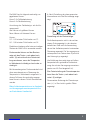
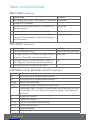
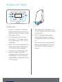
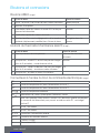
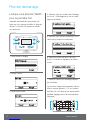
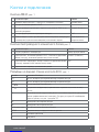
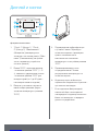
Accessories:
Wireless Room Unit and transmitter, motor package for second heating circuit, additional
Room Unit for second circuit. Adapters for various type of valves.
Vexve AM40 Heating
Controller delivery includes:
AM40 ECU, motor unit, connection
adapters for Vexve AM & Termomix type
valves. Power Supply 230 VAC/18 VAC.
External temperature sensor (NTC) with 15
meter wire and wall mount box.
Supply water temperature sensor (KTY) with
3 meter wire & pipe attachment ties.
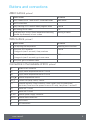
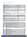
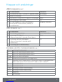
Pack A, wireless room unit and transmitter part
Product no. 1140041 // EAN 6415843670558
· Wireless room unit
· Alkaline AA batteries 3 pcs included (lifetime over two years)
· antenna unit for the central unit AM40 with 1.5-m cable
Pack B, heating circuit 2 motor package
Product no. 1140042 // EAN 6415843670565
· valve motor 24 VAC with 1.5-metre cable and quick connector
· return water sensor with 3-metre cable and quick connector
· connection equipment for Vexve AMV and Automix type valves
Pack C, additional room unit
Product no. 1140043 // EAN 6415843670572
· wireless room unit for second circuit
· Alkaline AA batteries 3 pcs included
2
3
www.vexve.fi.
www.vexve.fi.


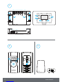
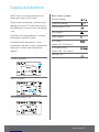
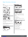
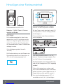
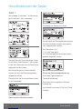
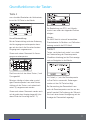
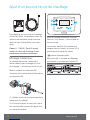
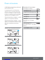
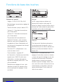
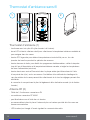
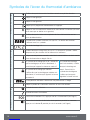
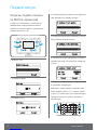
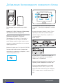
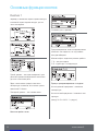
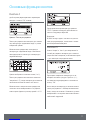
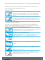
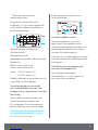
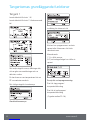
AM40 buttons, picture 1
Basic screen In menus
1 basic screen circuit 1 and circuit 2, measured values main menu
2 fast Eco functions
3 easy checking ECO mode & Week program values Cancel
4 fast editing Circuit values OK
5 Up&Down keys for fast Room temperature finetuning
(parallel displacement) in basic screen
moving in menus
WRU buttons, picture 2
Basic screen In menus
A For adjusting the temperature selecting menu functions
B One push: ECO mode on
A long push (over 3 seconds): Away mode on
Cancel
C One push: accept selection
A long push (over 3 seconds): go to user menu
OK
D One push: go to installation menu
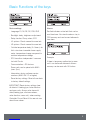
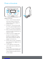
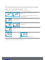
Connectors in the backside of ECU, picture 1
RF antenna unit connector
IN1 supply water temperature sensor 1-circuit
IN2 supply water temperature sensor 2-circuit
IN3 external temperature sensor
IN4 contact info (away switch) /sensor
R1 potential free relay 2Amp inductive, screw contact (only for professional
electrician) Cover must be opened to acces R1 relay, see picture 1 section C
M1 motor unit 1-circuit
M2 motor unit 2-circuit
18 VAC external power supply connector
EXTI/O external data connection
AWall mounts
BDIN connectors
Buttons and connections
5
www.vexve.fi.

A
B
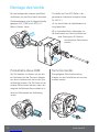
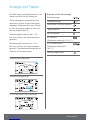
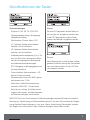
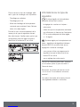
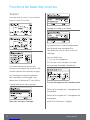
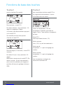
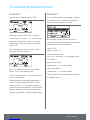
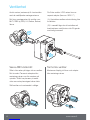
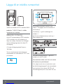
Vexve AMV range:
The pin is already in the right-hand side of
the valve. Only the Termomix adapter from
the installation kit should be installed on the
stem. The pin side may be changed if the
engine position requires it.
Place valve and motor unit in zero position.
Termomix valves:
A suitable pin screw and adapter from the
installation kit should be installed.
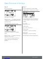
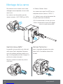
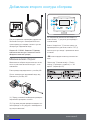
Valve assembly
Connect motor(s) to mixing valve with
included connection adapters.
Motor units are suitable for valves like:
MUT, ESBE (not VRG), LK, Belimo, Barberi,
Vexve.
Esbe VRG serie valves has separate
adapter part available (Vexve nr.1920117)
( A ) Check the valve operational direction
before installation.
( B ) In manual mode check that valve/
motor combination turn 90-degrees with
reasonable torque!
6
7www.vexve.fi.

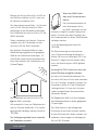
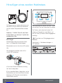
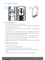
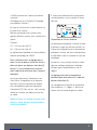
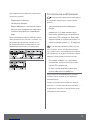
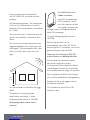
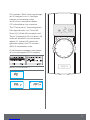
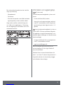
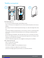
If AM40 consist also
Wireless Room unit:
Connect RF-antenna unit to
RF-connector in AM40, place
antenna as high as possible.
Antenna can be lenghtened
for better RF-reception with ready wire.
(10 meter extension cord Vexve nro.
1920096)
Relay control is used for example pump
control, in that case 230 VAC wire must
be connected to go thru R1 connector by
opening the cover of AM40.
Notice 230 VAC connection needs
professional electrician!!
Contact info connector IN4 connector can
be a normal on/o switch. (Away switch as
default set). It is also usable for future temp.
sensor use.
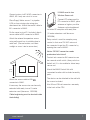
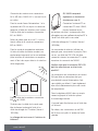
Attach the AM40 Control Unit with
convenient location with included assembly
parts.
The device can be attached to the wall with
the screws included.
Also 35 mm DIN-rail connectors are ready
in the back of the CPU.
Connect motors to M1 & M2 connectors in
AM40, M1 if only one circuit is in use.
Place Supply Water sensor 1 to pipeline
5-25 cm from mixing valve using pipe
attachment ties. Attach the sensor cable to
IN1 connector in AM40.
Do the same in circuit 2 if included, attach
sensor cable to IN2 connector in AM40.
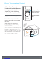
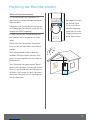
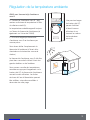
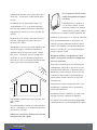
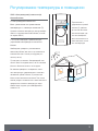
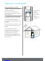
Attach the external temperature sensor
using wall mount box to suitable place in
outer wall. (Secure location, not direct
sunlight or snow / rain to sensor box).
min.
2 m
Attach the sensor cable to IN3
connector in AM40.
If necessary the sensor wire can be easily
extended with ready to use 10 meter
extension cord (Vexve nro. 1920096).
Cable lenghtening must be located inside
the building!
6
7
www.vexve.fi.
www.vexve.fi.

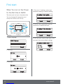
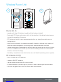
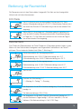
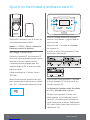
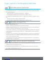
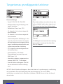
First start
When You turn on the Power
for the first time to AM40
The device ask for basic information that
You can change with arrow keys and
accept the choices witk OK key.
1. Select language
2. Set time
3. Set date
4. Set circuit 1 heating system type,
underfloor heating or radiator heating
5. Set the valve operational direction,
clockwise or counterclockwise
6. Set Your own supply water temp. limits
or accept the factory default settings
8
9www.vexve.fi.

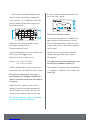
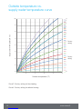
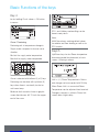
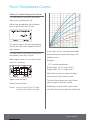
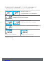
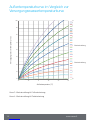
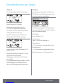
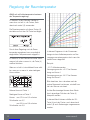
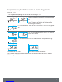
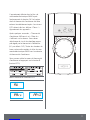
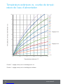
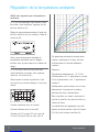
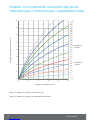
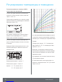
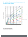
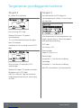
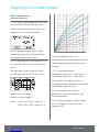
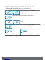
7. Set Outdoor-controlled heating curve.
The Left-hand side buttons change the
curve (buttons 1-2), Up&down buttons (5)
are for parallel displacement (finetune of
inner temperature)
AM40 has the following default curves:
Underfloor heating Curve 2
Radiator heating Curve 4
Type of building aect to curve selection as:
Old houses with bigger curves
New houses with smaller curves
Curves: 0.2 - 5.0 in 0.2 steps
5.0 - 9.5 in 0.5 steps
Parallel displacement is not adviced to be
used when You start AM40 for the first time.
For end user finetuning is very easy in
basic display with up&down buttons (5) if
there is constantly too high or low temp in
living area.
When You use a wireless room unit it is
natural to control living area temperature
with RF-Room unit. In that case You can
accept factory default curves in this step.
See outside temp vs. supply water temp.
curve at the end of this manual!
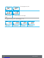
8. After setting up above information You
are in the basic display
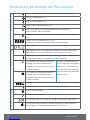
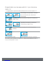
Situation in the basic screen:
The outside temperature is displayed top
right corner and the line below it shows
that outside temperature control is in use,
supply water temp is seen next to heating
type symbol.
(above You can see outside controlled
radiator heating where supply water is
45-degrees)
Fine adjustment to room temperature can
be done with up&down buttons (5).
The expected change in room temperature,
(+/-) degrees is showed on the screen with
large digits
8
9

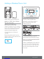
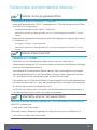
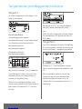
Adding a Wireless Room Unit
Wireless Room Unit for the AM40 ECU:
product nr. 1140041: Pack A, Wireless
room Unit & Transmitter
Mechanical assembly:
Connect RF-antenna unit to RF-connector
in ECU, place antenna as high as possible.
Antenna can be extended for better RF-
reception with ready coupled wire.
(10 meter extension cord Vexve nro.
1920096)
Remove the protective plastic from the
batteries in Room Unit and check that “RU”
appears on the screen
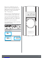
After mechanical assembly press button 1
two times to reach the Main menu.
Main menu >> go to Device settings >>
go to Communication menu using
up&down buttons (5)
In Communication menu >> go to RF-
devices where You find RF-devices section
Room unit must be powered and word RU
must be on the screen!
(If there is something else on the screen You
must press the commissioning button D on
the room unit with tip of a pen. Select DE
fa
from the commissioning menu and select
Yes for that.
10
11www.vexve.fi.

Pairing starts in AM40 ECU when OK
button is pushed. Immediatelly after that
Right button in room unit must be pressed
too. Now LCD-screens show the texts
”Pair” / “Device pair-up”
After few seconds “Found AM Room Unit”
& “Pair ok” appears on the screens. Now
You must choose the right heating circuit
which room unit controls (H1 default / H2)
and after that all basic data is copied from
AM40 ECU to room unit memory..
You can leave Room Unit menu by pressing
button B (ECO-button)
Room unit menus >>
10
11

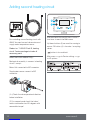
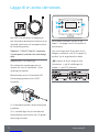
Adding second heating circuit
For controlling second heating circuit with
AM40 You need second valve motor and
supply water temperature sensor
Product nr. 1140042: Pack B, heating
circuit 2 motor package includes all
necessary parts
Mechanical assembly:
Mechanical assembly is same as in heating
circuit 1 except:
Motor Unit connected to M2 connector.
Supplywater sensor connect to IN2
connector.
A
B
( A ) Check the valve operational direction
before installation.
( B ) In manual mode check that valve/
motor combination turn 90-degrees with
reasonable torque!
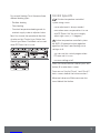
After mechanical assembly press button 1
two times to reach the Main menu
Up/down buttons (5) are used for moving in
menus OK button (4) is for enter / accepting
values.
button is for undo/exit.
Main menu >> go to Device settings >> go
to H2 options
12
13www.vexve.fi.

For second Heating Circuit there are three
dierent heating types:
· Radiator heating
· Floor heating
· Constant temperature heating mode to
maintain supply water in adjusted value.
Next You choose the operational direction
of valve and last Control type. Notice that
Control type Room Controlled can be used
when RF Room Unit is in use.
Control type info
Outdoor temperature controlled
system using curves
· curve adjustment is always needed
· even when room compensation is in use
with RF-Room Unit You must roughly
adjust right curve (+/- 5 degrees)
Indoor temperature controlled system
àla AM20-W patented indoor regulation
algorithm that don’t need heating curve
settings at all.
· you can use this control program when
RF-room unit is in use
· no curve settings at all
When You have made the choises press exit
button (3) to enter basic screen.
From now on You find Circuit 1 and Circuit 2
basic screens behind the button number 1.
Measured values and Main menu are also
found behind that button.
12
13


AM40 buttons, picture 1
Basic screen In menus
1 basic screen circuit 1 and circuit 2, measured values main menu
2 fast Eco functions
3 easy checking ECO mode & Week program values Cancel
4 fast editing Circuit values OK
5 Up&Down keys for fast Room temperature finetuning
(parallel displacement) in basic screen
moving in menus
WRU buttons, picture 2
Basic screen In menus
A For adjusting the temperature selecting menu functions
B One push: ECO mode on
A long push (over 3 seconds): Away mode on
Cancel
C One push: accept selection
A long push (over 3 seconds): go to user menu
OK
D One push: go to installation menu
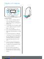
Connectors in the backside of ECU, picture 1
RF antenna unit connector
IN1 supply water temperature sensor 1-circuit
IN2 supply water temperature sensor 2-circuit
IN3 external temperature sensor
IN4 contact info (away switch) /sensor
R1 potential free relay 2Amp inductive, screw contact (only for professional
electrician) Cover must be opened to acces R1 relay, see picture 1 section C
M1 motor unit 1-circuit
M2 motor unit 2-circuit
18 VAC external power supply connector
EXTI/O external data connection
AWall mounts
BDIN connectors
Buttons and connections
4
5
www.vexve.fi.
www.vexve.fi.

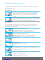
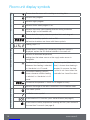
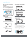
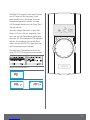
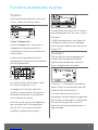
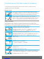
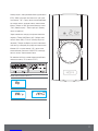
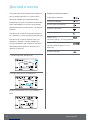
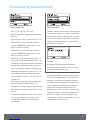
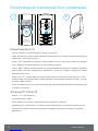
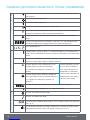
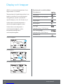
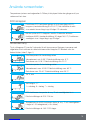
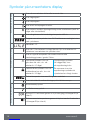
Display and buttons
AM40 shows outside temperature in the
upper right corner of the screen.
Supply water temperature is shown beside
heating type symbol. Curved lines on top of
the heating type symbol shows that heating
is on.
Underlined outside temperature = outdoor
temperature-controlled system
Underlined room temperature = room
temperature controlled system, temperature
adjustment in direct room temperature
degrees
Outdoor controlled
Room Controlled
Eco holiday mode in use
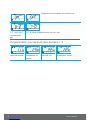
Basic screen symbols:
Radiator heating
Underfloor heating
Week program in use
Day program
Night program
Eco mode
(default 8h, 20.5 Celsius)
Eco holiday mode
(default 30d, 18.5 Celsius)
Heating is on
6
7www.vexve.fi.
Sidan laddas...
Sidan laddas...
Sidan laddas...
Sidan laddas...
Sidan laddas...
Sidan laddas...
Sidan laddas...
Sidan laddas...
Sidan laddas...
Sidan laddas...
Sidan laddas...
Sidan laddas...
Sidan laddas...
Sidan laddas...
Sidan laddas...
Sidan laddas...
Sidan laddas...
Sidan laddas...
Sidan laddas...
Sidan laddas...
Sidan laddas...
Sidan laddas...
Sidan laddas...
Sidan laddas...
Sidan laddas...
Sidan laddas...
Sidan laddas...
Sidan laddas...
Sidan laddas...
Sidan laddas...
Sidan laddas...
Sidan laddas...
Sidan laddas...
Sidan laddas...
Sidan laddas...
Sidan laddas...
Sidan laddas...
Sidan laddas...
Sidan laddas...
Sidan laddas...
Sidan laddas...
Sidan laddas...
Sidan laddas...
Sidan laddas...
Sidan laddas...
Sidan laddas...
Sidan laddas...
Sidan laddas...
Sidan laddas...
Sidan laddas...
Sidan laddas...
Sidan laddas...
Sidan laddas...
Sidan laddas...
Sidan laddas...
Sidan laddas...
Sidan laddas...
Sidan laddas...
Sidan laddas...
Sidan laddas...
Sidan laddas...
Sidan laddas...
Sidan laddas...
Sidan laddas...
Sidan laddas...
Sidan laddas...
Sidan laddas...
Sidan laddas...
Sidan laddas...
Sidan laddas...
Sidan laddas...
Sidan laddas...
Sidan laddas...
Sidan laddas...
Sidan laddas...
Sidan laddas...
Sidan laddas...
Sidan laddas...
Sidan laddas...
Sidan laddas...
Sidan laddas...
Sidan laddas...
Sidan laddas...
Sidan laddas...
Sidan laddas...
Sidan laddas...
Sidan laddas...
Sidan laddas...
Sidan laddas...
Sidan laddas...
Sidan laddas...
Sidan laddas...
Sidan laddas...
Sidan laddas...
Sidan laddas...
Sidan laddas...
Sidan laddas...
Sidan laddas...
Sidan laddas...
Sidan laddas...
Sidan laddas...
Sidan laddas...
Sidan laddas...
Sidan laddas...
Sidan laddas...
Sidan laddas...
Sidan laddas...
Sidan laddas...
Sidan laddas...
Sidan laddas...
Sidan laddas...
Sidan laddas...
Sidan laddas...
Sidan laddas...
Sidan laddas...
Sidan laddas...
Sidan laddas...
Sidan laddas...
Sidan laddas...
Sidan laddas...
Sidan laddas...
Sidan laddas...
Sidan laddas...
Sidan laddas...
Sidan laddas...
Sidan laddas...
Sidan laddas...
Sidan laddas...
Sidan laddas...
Sidan laddas...
Sidan laddas...
Sidan laddas...
Sidan laddas...
Sidan laddas...
Sidan laddas...
Sidan laddas...
-
 1
1
-
 2
2
-
 3
3
-
 4
4
-
 5
5
-
 6
6
-
 7
7
-
 8
8
-
 9
9
-
 10
10
-
 11
11
-
 12
12
-
 13
13
-
 14
14
-
 15
15
-
 16
16
-
 17
17
-
 18
18
-
 19
19
-
 20
20
-
 21
21
-
 22
22
-
 23
23
-
 24
24
-
 25
25
-
 26
26
-
 27
27
-
 28
28
-
 29
29
-
 30
30
-
 31
31
-
 32
32
-
 33
33
-
 34
34
-
 35
35
-
 36
36
-
 37
37
-
 38
38
-
 39
39
-
 40
40
-
 41
41
-
 42
42
-
 43
43
-
 44
44
-
 45
45
-
 46
46
-
 47
47
-
 48
48
-
 49
49
-
 50
50
-
 51
51
-
 52
52
-
 53
53
-
 54
54
-
 55
55
-
 56
56
-
 57
57
-
 58
58
-
 59
59
-
 60
60
-
 61
61
-
 62
62
-
 63
63
-
 64
64
-
 65
65
-
 66
66
-
 67
67
-
 68
68
-
 69
69
-
 70
70
-
 71
71
-
 72
72
-
 73
73
-
 74
74
-
 75
75
-
 76
76
-
 77
77
-
 78
78
-
 79
79
-
 80
80
-
 81
81
-
 82
82
-
 83
83
-
 84
84
-
 85
85
-
 86
86
-
 87
87
-
 88
88
-
 89
89
-
 90
90
-
 91
91
-
 92
92
-
 93
93
-
 94
94
-
 95
95
-
 96
96
-
 97
97
-
 98
98
-
 99
99
-
 100
100
-
 101
101
-
 102
102
-
 103
103
-
 104
104
-
 105
105
-
 106
106
-
 107
107
-
 108
108
-
 109
109
-
 110
110
-
 111
111
-
 112
112
-
 113
113
-
 114
114
-
 115
115
-
 116
116
-
 117
117
-
 118
118
-
 119
119
-
 120
120
-
 121
121
-
 122
122
-
 123
123
-
 124
124
-
 125
125
-
 126
126
-
 127
127
-
 128
128
-
 129
129
-
 130
130
-
 131
131
-
 132
132
-
 133
133
-
 134
134
-
 135
135
-
 136
136
-
 137
137
-
 138
138
-
 139
139
-
 140
140
-
 141
141
-
 142
142
-
 143
143
-
 144
144
-
 145
145
-
 146
146
-
 147
147
-
 148
148
-
 149
149
-
 150
150
-
 151
151
-
 152
152
-
 153
153
-
 154
154
-
 155
155
-
 156
156


på andra språk
- Deutsch: Vexve AM40
- français: Vexve AM40
Andra dokument
-
 Purmo Alaid RF Installationsguide
-
 Purmo Ulow E2 Installationsguide
-
Regin OPTIGO OP10 Bruksanvisningar
-
 MESCOLI LK100 Användarmanual
-
Nibe RMU S40 Room Unit Användarmanual
-
Yamaha DPX-530 Bruksanvisning
-
-
-
 Westerbergs Arum Installation Instructions And User Manual
-
LK Armatur SmartComfort LK 130 Användarmanual


