Yamaha DPX-530 Bruksanvisning
- Kategori
- Projektorer
- Typ
- Bruksanvisning

YAMAHA ELECTRONICS CORPORATION, USA
6660 ORANGETHORPE AVE., BUENA PARK, CALIF. 90620, U.S.A.
YAMAHA CANADA MUSIC LTD.
135 MILNER AVE., SCARBOROUGH, ONTARIO M1S 3R1, CANADA
YAMAHA ELECTRONIK EUROPA G.m.b.H.
SIEMENSSTR. 22-34, 25462 RELLINGEN BEI HAMBURG, GERMANY
YAMAHA ELECTRONIQUE FRANCE S.A.
RUE AMBROISE CROIZAT BP70 CROISSY-BEAUBOURG 77312 MARNE-LA-VALLEE CEDEX02, FRANCE
YAMAHA ELECTRONICS (UK) LTD.
YAMAHA HOUSE, 200 RICKMANSWORTH ROAD WATFORD, HERTS WD18 7GQ, ENGLAND
YAMAHA SCANDINAVIA A.B.
J A WETTERGRENS GATA 1, BOX 30053, 400 43 VÄSTRA FRÖLUNDA, SWEDEN
YAMAHA MUSIC AUSTRALIA PTY, LTD.
17-33 MARKET ST., SOUTH MELBOURNE, 3205 VIC., AUSTRALIA
©
2005 All rights reserved.
DPX-530
Printed in Japan 871D460B10
EB
OWNER
’
S MANUAL
DPX-530
Digital Cinema Projector
Projecteur Cineme Numerique
MODE D’EMPLOI
BEDIENUNGSANLEITUNG
MANUALE DI ISTRUZIONI
MANUAL DE INSTRUCCIONES
BRUKSANVISNING
GEBRUIKSAANWIJZING
01EN_DPX-530_EX-cv.fm Page 1 Friday, May 20, 2005 5:51 PM

i
IMPORTANT SAFETY INSTRUCTIONS
• Explanation of Graphical Symbols
The lightning flash with arrowhead symbol,
within an equilateral triangle, is intended to alert
you to the presence of uninsulated “dangerous
voltage” within the product’s enclosure that may
be of sufficient magnitude to constitute a risk of
electric shock to persons.
The exclamation point within an equilateral
triangle is intended to alert you to the presence of
important operating and maintenance (servicing)
instructions in the literature accompanying the
appliance.
Please read all these instructions regarding your projector and retain
them for future reference. Follow all warnings and instructions
marked on the projector.
1 Read instructions: All the safety and operating instructions
should be read before the appliance is operated.
2 Retain instructions: The safety and operating instructions
should be retained for future reference.
3 Warnings: All warnings on the appliance and in the operating
instructions should be adhered to.
4 Instructions: All operating instructions must be followed.
5 Cleaning: Unplug this projector from the wall outlet before
cleaning it. Do not use liquid aerosol cleaners.
6 Attachments and equipment: Never add any attachments
and/or equipment without the approval of the manufacturer as
such additions may result in the risk of fire, electric shock or
other personal injury.
7 Water and moisture: Do not use this projector near water or
in contact with water.
8 Accessories: Do not place this projector on
an unstable cart, stand, tripod, bracket or
table. Use only with a cart, stand, tripod
bracket, or table recommended by the
manufacturer or sold with the projector. Any
mounting of the appliance should follow the
manufacturer's instructions and should use a
mounting accessory recommended by the manufacturer.
An appliance and cart combination should be moved with care.
Quick stops, excessive force and uneven surfaces may cause the
appliance and cart combination to overturn.
9 Ventilation: Slots and openings in the cabinet are provided for
ventilation, ensuring reliable operation of the projector and to
protect it from overheating. Do not block these openings or
allow them to be blocked by placing the projector on a bed,
sofa, rug, or bookcase. Ensure that there is adequate ventilation
and that the manufacturer's instructions have been adhered to.
10 Power sources: This projector should be operated only from
the type of power source indicated on the marking label. If you
are not sure of the type of power, please consult your appliance
dealer or local power company.
11 Power-cable protection: Power-supply cables should be
routed so that they are not likely to be walked on or pinched by
items placed upon or against them. Pay particular attention to
cords at plugs, convenience receptacles, and points where they
exit from the appliance.
12 Overloading: Do not overload wall outlets and extension
cords as this can result in a fire or electric shock.
13 Objects and liquids: Never push objects of any kind through
openings of this projector as they may touch dangerous voltage
points or short-out parts that could result in a fire or electric
shock. Never spill liquid of any kind on the projector.
14 Servicing: Do not attempt to service this projector yourself.
Refer all servicing to qualified service personnel.
15 Damage requiring service: Unplug this projector from the
wall outlet and refer servicing to qualified service personnel
under the following conditions:
(a) If the power-supply cable or plug is damaged.
(b)If liquid has been spilled, or objects have fallen into the
projector.
(c) If the projector does not operate normally after you follow
the operating instructions. Adjust only those controls that are
covered by the operating instructions. An improper
adjustment of other controls may result in damage and may
often require extensive work by a qualified technician to
restore the projector to its normal operation.
(d)If the projector has been exposed to rain or water.
(e) If the projector has been dropped or the cabinet has been
damaged.
(f) If the projector exhibits a distinct change in performance -
this indicates a need for service.
16 Replacement parts: When replacement parts are required,
be sure that the service technician has used replacement parts
specified by the manufacturer or parts having the same
characteristics as the original part. Unauthorized substitutions
may result in fire, electric shock or other hazards.
17 Safety check: Upon completion of any service or repair to
this projector, ask the service technician to perform safety
checks determining that the projector is in a safe operating
condition.
18 Connection cable: Use the supplied RS-232C and RGB
cables with this equipment to keep interference within the limits
of an FCC/EN55022 Class B device.
CAUTION: TO REDUCE THE RISK OF
ELECTRIC SHOCK, DO NOT REMOVE
COVER (OR BACK). NO USER-SERVICEABLE
PARTS INSIDE. REFER SERVICING TO QUALIFIED
SERVICE PERSONNEL.
WARNING
TO REDUCE THE RISK OF FIRE OR ELECTRIC SHOCK,
DO NOT EXPOSE THIS UNIT TO RAIN OR MOISTURE.
For Canadian customers
To prevent electric shock, match wide blade of plug to
wide slot and fully insert.
This Class B digital apparatus complies with Canadian ICES-
003.
IMPORTANT!
Please record the serial number of this unit in the space below.
Model:
Serial No.:
The serial number is located on the bottom of the unit.
Retain this Owner’s Manual in a safe place for future reference.
CAUTION
RISK OF ELECTRIC SHOCK
DO NOT OPEN

ii
COMPLIANCE INFORMATION STATEMENT
(DECLARATION OF CONFORMITY PROCEDURE)
Responsible Party: Yamaha Electronics Corporation
Address: 6660 Orangethorpe Avenue
Buena Park, CA90620
Telephone: 714-522-9105
Fax: 714-670-0108
Type of Equipment: Projector
Model Name: DPX-530
This device complies with Part 15 of the FCC Rules.
Operation is subject to the following conditions:
1) this device may not cause harmful interference, and
2) this device must accept any interference received including interference that may cause undesired operation.
See the owner’s manual instructions if interference to radio reception is suspected.
FCC INFORMATION (for US customers only)
1. IMPORTANT NOTICE: DO NOT MODIFY THIS
UNIT!
This product, when installed as indicated in the instructions
contained in this manual, meets FCC requirements.
Modifications not expressly approved by Yamaha may void
your authority, granted by the FCC, to use the product.
2. IMPORTANT: When connecting this product to accessories
and/or another product use only high quality shielded cables.
Cable/s supplied with this product MUST be used. Follow
all installation instructions. Failure to follow instructions
could void your FCC authorization to use this product in the
USA.
3. NOTE: This product has been tested and found to comply
with the requirements listed in FCC Regulations, Part 15 for
Class “B” digital devices. Compliance with these
requirements provides a reasonable level of assurance that
your use of this product in a residential environment will not
result in harmful interference with other electronic devices.
This equipment generates/uses radio frequencies and, if not
installed and used according to the instructions found in the
users manual, may cause interference harmful to the operation of
other electronic devices.
Compliance with FCC regulations does not guarantee that
interference will not occur in all installations. If this product is
found to be the source of interference, which can be determined
by turning the unit “OFF” and “ON”, please try to eliminate the
problem by using one of the following measures:
Relocate either this product or the device that is being affected
by the interference.
Utilize power outlets that are on different branch (circuit breaker
or fuse) circuits or install AC line filter/s.
In the case of radio or TV interference, relocate/reorient the
antenna. If the antenna lead-in is 300 ohm ribbon lead, change
the lead-in to coaxial type cable.
If these corrective measures do not produce satisfactory results,
please contact the local retailer authorized to distribute this type
of product. If you can not locate the appropriate retailer, please
contact Yamaha Electronics Corp., U.S.A. 6660 Orangethorpe
Ave, Buena Park, CA 90620.
The above statements apply ONLY to those products distributed
by Yamaha Corporation of America or its subsidiaries.

iii
Caution: Read this before operating this unit.
Warning
• This unit must be grounded
• Do not use this projector in a computer room
This projector is not for use in a computer room, as defined in
the Standard for the Protection of Electronic Computer/Data
Processing Equipment, ANSI/NFPA 75.
• Unplug immediately if there is something wrong with
your projector
Do not operate if smoke, strange noise or odor comes out of
the projector. It might cause fire or electric shock. If this
happens, unplug immediately and contact your dealer.
• Never remove the cabinet
This projector contains high voltage circuitry. An inadvertent
contact may result in an electric shock. Except as specifically
explained in the owner's manual, do not attempt to service
this product yourself. Contact your dealer when you want to
fix, adjust or inspect the projector.
• Do not modify this projector
It can lead to fire or electric shock.
• Do not continue using this projector if you drop or
break it
Unplug the projector and contact your dealer for inspection.
It may lead to fire if you continue using it.
• Do not face the projector lens towards the sun
It can lead to fire.
• Use correct voltage
If you use incorrect voltage, it can lead to fire.
• Do not place the projector on uneven or unstable
surfaces
Place the projector on a leveled and stable surface only.
• Do not look into the lens when it is operating
It may cause serious eye injury.
• Do not turn off the main power abruptly or unplug the
projector during operation
It can lead to lamp breakage, fire, electric shock or other
trouble. Always wait for the fan to turn off before turning the
main power off.
• Avoid all contact with the air exhaust vents and
bottom plate
The air exhaust vents and bottom plate heat up during
operation and may cause personal injury or damage to other
equipment. Do not touch them, place other equipment in front
of the air exhaust vents, or set the projector on a desk which is
easily affected by heat.
• Do not look into the air exhaust vent when the
projector is operating
Heat, dust, etc. may blow out of it and cause injury to your
eyes.
• Do not block the air intake and exhaust vents
If they are blocked, heat may be generated inside the
projector, causing deterioration in the projector quality and/or
fire.
Place of installation
For safety reasons, refrain from setting the projector at any place
subjected to high temperature and high humidity. Maintain an
operating temperature, humidity and setting as specified below:
• Operating temperature: between 41°F (5°C) and 95°F (35°C).
• Operating humidity: between 30 and 90%
• Never put any heat-producing device under the projector. The
projector may overheat.
• Do not install the projector near any equipment that produces a
strong magnetic field. Also refrain from installing near the
projector any cable carrying a large current.
• Do not install the projector in a place that is unstable or subject
to vibration; otherwise, it may fall and cause serious injury
and/or damage to the unit.
• Do not stand the projector on its side; otherwise, it may fall and
cause serious injury and/or damage to the unit.
• Slanting the projector more than 10° right/left or 15°
forward/backward may cause serious problems, such as the
lamp to explode.
• Do not place the projector near an air conditioning unit or heater
to avoid hot air to the vents of the projector.
European compliance notice
This video projector complies with the requirements of the EC
Directive 89/336/EEC “EMC Directive” as amended by Directive
92/31/EEC and 93/68/EEC, and 73/23/EEC “Low Voltage
Directive” as amended by Directive 93/68/EEC.
This unit is not disconnected from the AC power source as long
as it is connected to the wall outlet, even if this unit itself is
turned off. This state is called the standby mode. In this state,
this unit is designed to consume a very small quantity of power.
For U.K. customers
If the socket outlets in the home are not suitable for the plug
supplied with this appliance, it should be cut off and an
appropriate 3-pin plug fitted. For details, refer to the instructions
described below.
Note
• The plug severed from the mains lead must be destroyed, as a plug
with a bared flexible cord is hazardous if engaged in a live socket
outlet.
IMPORTANT
THE WIRES IN THIS MAINS LEAD ARE COLOURED IN
ACCORDANCE WITH THE FOLLOWING CODE:
GREEN-AND-YELLOW: EARTH
BLUE: NEUTRAL
BROWN: LIVE
As the colours of the wires in the mains lead of this apparatus
may not correspond with the coloured markings identifying the
terminals in your plug, proceed as follows:
The wire which is coloured GREEN-AND-YELLOW must be
connected to the terminal in the plug which is marked by the
letter “E” or the safety earth symbol or coloured GREEN or
GREEN-AND-YELLOW.
The wire which is coloured BLUE must be connected to the
terminal marked with the letter “N” or coloured BLACK.
The wire which is coloured BROWN must be connected to the
terminal marked with the letter “L” or coloured RED.

1
Table of contents
1 Preparation 2
Inappropriate places for installation .....................2
Accessory check ..................................................3
Inserting the batteries into the remote control......4
2 Controls and functions 5
Projector overview ...............................................5
Remote control overview .....................................6
Using the picture quality adjusting buttons .....6
3 Using the remote control 7
Operational range ................................................7
Reception angle ...................................................7
4 Setting up the projector 8
Setting up your projector......................................8
Basic projector setup ...........................................8
Adjusting the projection angle..............................8
Screen size and projection distance ....................9
5 Connections 10
Basic home theater system connection .............10
Connecting to a video player, etc.......................11
Connecting to a DVD player ..............................11
DVI-D connections .............................................12
D-SUB connections............................................12
Connecting the projector to a computer.............13
Plugging in the power cable...............................13
6 Projection 14
Viewing video images ........................................14
To stop projecting: ........................................15
KEYSTONE adjustment................................15
IRIS button ....................................................15
Setting the aspect ratio .................................16
Changing the settings ...................................16
Viewing computer images..................................17
AUTO / AUTO SYNC buttons .......................18
When connected to a notebook computer: ...18
To stop projecting: ........................................18
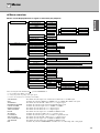
7Menu 19
Menu overview...................................................19
How to set the menus ...................................20
Menu settings.....................................................21
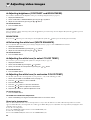
8 Adjusting video images 24
Adjusting brightness
(CONTRAST and BRIGHTNESS) .....................24
CONTRAST ..................................................24
BRIGHTNESS...............................................24
Enhancing the white level
(WHITE ENHANCE) ..........................................24
Adjusting the white tone
(to select COLOR TEMP.) .................................24
Adjusting the white tone
(to customize COLOR TEMP.)...........................24
About color temperature ...............................24
Adjusting color (SATURATION and HUE) .........25
SATURATION...............................................25
HUE ..............................................................25
Sharpening or softening images
(SHARPNESS).................................................. 25
LPF (Progressive filter) ..................................... 25
9 MEMORY function 26
MEMORY function ............................................ 26
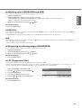
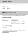
10 Adjusting computer images 26
Adjusting computer images............................... 26
Simple method to adjust the image
position......................................................... 26
11 Ceiling installation 27
Viewing ceiling mounted projector images........ 27
Dimension Drawings (unit: mm) ........................ 27
12 Replacing the lamp 28
Interval of lamp replacement............................. 28
Replacing the lamp ........................................... 29
Maintenance...................................................... 29
13 Attaching a lens filter and cap 30
Attaching a commercially available lens filter.... 30
Attaching the lens cap....................................... 30
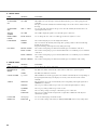
14 Troubleshooting 31
Troubleshooting ................................................ 31
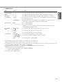
15 Indicators 34
Normal conditions ............................................. 34
Abnormal condition ........................................... 34
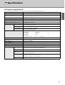
16 Specifications 35
Projector specifications ..................................... 35
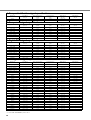
Composite / S-video signal specifications......... 36
Component signal specifications....................... 36
Digital RGB signal specifications ...................... 36
Analog RGB signal specifications ..................... 36

2
◆ Inappropriate places for installation
If this unit is not correctly installed in an appropriate place, it may cause fire or failure, or damage the unit itself. Carefully choose the place to
install this unit by avoiding the places listed below.
1. Places where the temperature and humidity vary greatly
• Do not install this unit in a place where the temperature and humidity become extremely high or the temperature becomes extremely
low.
• This unit must be used within a temperature range of 41°F (5°C) to 95°F (35°C).
• This unit must be used within a humidity range of 30 to 90%
2. Places without adequate ventilation
• Install this unit with at least 30 cm (1 feet) of ventilation space on the top, right and left, and back.
• Do not cover the ventilation slots of this unit. Covering the slots will obstruct heat dissipation.
• Install this unit on the firm surface.
• Do not cover this unit with a tablecloth, etc.
• Make sure there is nothing to get sucked into the ventilation slots so that the temperature of this unit does not become too high.
• If you are going to install the unit in a rack, be sure to leave space for ventilation to prevent exhaust overheating the unit.
3. Places where it gets dusty
• If the filter is blocked with dust, the temperature of this unit may become too high.
4. Places with too much vibration or impact
• Vibration and impact can damage parts of this unit.
5. Places where this unit gets exposed to water or high humidity
• If this unit is exposed to water of high humidity, it may cause a fire or electrical shock.
6. Unstable places
• If this unit is installed on an unstable or an inclined tabletop, it may fall and cause damage to the unit or personal injury.
7. In close proximity to a radio or stereo
• The unit may interfere with reception if placed in close proximity to a radio or television receiver.
8. Uneven surfaces
• Slanting the projector more than 10° right and left or 15° front and rear may cause problems (such as the lamp exploding).
Warning
• To ensure vivid, high contrast images, make sure that no light other than the projector light falls directly on the screen.
Preparation1

3
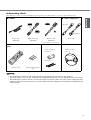
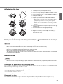
◆ Accessory check
The following accessories are provided with this projector. Check to be sure that all of the accessories are packed in the package.
Important
• The supplied power cables are to be used exclusively for this product. Never use them for other products.
• The power cables for use in the U.S. and Europe are included with this projector. Use the appropriate one for your country.
• The provided power cable for the U.S. is rated at 120 V. Never connect this cable to any outlet or power supply using other
voltages or frequencies than rated. If you use a power supply using other voltage than rated, prepare an appropriate power
cable separately.
■ Cables ■ Power supply parts
S-video cable
(WF76950)
RGB cable for PC
(WF76940)
RS-232C cable
(WF76930)
Power cable
• Used for adjustment by service person.
■ Remote control
parts
■ Ferrite core set ■ Others
• Instruction guide
• Ferrite core
• Band (two)
• Owner’s manual
• Lens cap
Remote control R03 (Size-AAA) battery
(two)
mini D-SUB
15-pin
mini D-SUB
15-pin
D-SUB 9-pin
8-pin
(For Europe)
(For US)

4
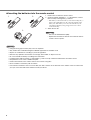
◆ Inserting the batteries into the remote control
1. Remove the rear lid of the remote control.
2. Check the polarity markings (+, –) of the batteries, and set
them correctly, inserting their (–) side first.
• If the battery is inserted from the (+) side first, inserting the (–)
side becomes difficult because the coil spring end hits on the
battery side. If the battery is forced to insert in this way, the
outer label of the battery may get ripped and cause a short-
circuit and heating.
3. Attach the rear lid.
Important
• Use two size-AAA batteries (R03).
• Replace the two batteries with new ones when the remote
control is slow to operate.
Caution
• Using the wrong type of battery may cause an explosion.
• Only Carbon-Zinc or Alkaline-Manganese Dioxide type batteries should be used.
• Dispose of used batteries according to your local regulations.
• Batteries may explode if misused. Do not recharge, disassemble, or dispose of in fire.
• Be sure to handle the battery according to the instructions.
• Load the battery with its positive (+) and negative (–) sides correctly oriented as indicated on the remote control.
• Keep batteries out of reach of children and pets.
• Remove the batteries, if the remote control is not used for a long time.
• Do not combine a new battery with an old one.
• If the solution of batteries comes in contact with your skin or clothes, rinse with water. If the solution comes in contact with
your eyes, rinse them with water and then consult your doctor.
1
2
3

5
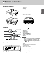
◆ Projector overview
1. FOCUS ring
2. ZOOM ring
3. Control panel
4. Air intake vent
5. Remote control sensor (Front)
6. Air exhaust vent
7. Air intake vent
8. Terminal board
9. Remote control sensor (Rear)
10. Air exhaust vent
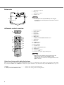
Control area
1. STANDBY / ON, button
2. AUTO SYNC, button
3. D-SUB / DVI, button
4. MENU button
5. STATUS indicator
6. POWER indicator
7. KEYSTONE, ENTER button
8. VIDEO / S / COMP., button
9. button
Important
• While the menu is on the screen, the KEYSTONE button
functions as the ENTER button and the D-SUB / DVI,
VIDEO / S / COMP., and AUTO SYNC buttons function as
the , , and buttons respectively.
Rear panel
1. AC IN
2. DVI input terminal (DVI-D 24-pin with HDCP)
3. D-SUB input terminal
4. Remote control sensor (Rear)
5. COMPONENT input terminals
6. Foot adjustment buttons (Left/Right)
7. Air exhaust vent
8. SERIAL terminal (8-pin)
• Used for adjustment by service person.
9. S-VIDEO input terminal
10. VIDEO input terminal
321
5
4
8
10
9
7
6
2
1
3
4
8
5
6
7
9
AC IN
DVI
D-SUB
SERIAL
S-VIDEO
VIDEO
COMPONENT
YP
B/CB PR/CR
23145
8766910
Controls and functions2

6
Bottom side
1. Adjustment foot (Front)
2. Lamp cover
3. Adjustment feet (Rear)
4. Air intake vent
Caution
• Do not replace the lamp immediately after using the
projector because the lamp will be extremely hot and may
cause burns.
◆ Remote control overview
1. IR signal transmitter
2. ON ( I ) button
3. DVI button
4. D-SUB button
5. ENTER button
6. MENU button
7. C.TEMP (COLOR TEMPERATURE) button*
8. AUTO button
9. IRIS button
10. GAMMA button*
11. ASPECT button
12. Direction buttons
13. S-VIDEO button
14. COMP. (COMPONENT) button
15. VIDEO button
16. STANDBY ( ) button
* See the below for the picture quality adjusting buttons.
Important
• When you press a button on the remote control, the
buttons on the remote control will light up. Wait
approximately 6 seconds after releasing the button for the
lights to turn off.
Using the picture quality adjusting buttons
When you press either of the picture quality adjusting buttons, the message for adjusting the picture quality appears. Adjust the picture quality
by pressing the GAMMA and C. TEMP buttons. The picture quality adjustment can be made alternatively in the IMAGE menu (see page 21).
GAMMA...............................................................Selects one of the preset gamma modes.
C. TEMP (COLOR TEMPERATURE) ................Selects one of the preset color temperatures.
3
2
1
4
1
2
3
4
5
6
7
8
9
16
15
14
13
12
11
10

7
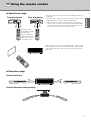
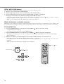
◆ Operational range
• Keep the remote control sensor out of direct sunlight or fluorescent
lamp light.
• Keep the remote control sensor at least 2 m away from fluorescent
lamps. Otherwise, the remote control may malfunction.
• If there is an inverter-operated fluorescent lamp near the remote
control, the remote control operation may become unstable. On this
occasion, stick a commercially available protection sticker on one
of the sensors that is closer to the fluorescent lamp.
When operating the remote control, keep the distance from the remote
control to the projector via the screen within about 5 m. The operable
range of the remote control, however, depends on the characteristics
of the screen.
◆ Reception angle
Vertical directions
Vertical directions (ceiling mount)
30˚30˚
30˚30˚
AC IN
Front of projector Rear of projector
Operate the remote
control within a distance
of 10 m from the
projector, pointing the
light beam at the remote
control sensor (front or
rear) of the projector.
20˚
10˚
20˚
10˚
20
20
˚
20
20
˚
Using the remote control3

8
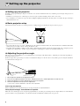
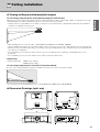
◆ Setting up your projector
Install the screen perpendicularly to the projector. If the screen can not be installed in such a way, adjust the projection angle of the projector as
shown below.
• Install the screen and projector so that the projector’s lens is placed at the horizontal position of the screen center.
• Do not install the screen where it is exposed to direct sunlight or lighting. Light directly reflecting on the screen makes the projected images
whitish and hard to view.
◆ Basic projector setup
Determine the distance from the screen to the projector according to the size of the images to be projected (see page 9).
• Do not place this projector on a carpet or blanket because the exhaust vent and the intake vent on the bottom surface will be blocked and the
inside of the projector will overheat, causing a breakdown or fire.
• Depending on the installation conditions, warm air that is emitted from the exhaust vents may flow into the intake vent, causing the projector
to display “Over Temperature” and then stop projecting images. If this happens, clear the area around the exhaust vent.
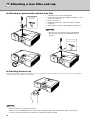
◆ Adjusting the projection angle
This projector is provided with three feet for adjusting the projection angle on the bottom surface. Adjust the projection angle depending on
the position of the projector.
For the best projection, project images on a flat screen installed at 90 degrees to the floor. If necessary, tilt the projector using the adjustment
feet on the bottom of the projector.
1. Tilt the projector upwards to the appropriate angle.
2. Press the foot adjustment buttons next to the adjustment feet (rear), and the adjustment feet will come out.
3. Release the buttons to lock the adjustment feet (rear) to that position.
4. Rotate the adjustment feet (rear) for fine adjustment.
• If necessary, rotate the adjustment feet (front) for fine adjustment.
After using the projector
Put the adjustment feet (rear) back into the projector by pressing the foot adjustment buttons.
When projected images are distorted to a trapezoid
When the screen and the projector are not placed perpendicularly to each other, projected images become trapezoidal. If you cannot make the
projector and the screen perpendicular to each other by mechanical adjustments, adjust keystone (see page 15).
W
A
A=B
B
STANDBY/ON
POWER STATUS
AUTO SYNC
ENTER
MENU
DIGITAL CINEMA PROJECTOR DPX-530
Screen
Adjustment feet (rear)
Setting up the projector4

9
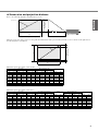
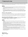
◆ Screen size and projection distance
Refer to the following diagram to determine the screen size.
When the aspect ratio of the screen is 4:3, the positional relation between the projected image and the screen is as shown on the right. Refer to
the following table for installation.
When the aspect ratio of the screen is 16:9
• The above figures are approximate and may be slightly different from the actual measurements.
When the aspect ratio of the screen is 4:3
• The above figures are approximate and may be slightly different from the actual measurements.
Screen size Projected distance (L)
Hd
16:9 Diagonal Height A Width B Min. Max.
inch cm inch cm inch cm inch m inch m inch cm
40 102 20 50 35 89 55 1.4 67 1.7 6.4 16.2
60 152 29 75 52 133 84 2.1 102 2.6 9.6 24.3
80 203 39 100 70 177 113 2.9 137 3.5 12.7 32.4
100 254 49 125 87 221 142 3.6 171 4.4 15.9 40.5
150 381 74 187 131 332 213 5.4 258 6.6 23.9 60.7
200 508 98 249 174 443 285 7.2 345 8.8 31.9 80.9
250 635 123 311 218 553 357 9.1 – – 39.8 101.1
275 699 135 342 240 609 393 10.0 – – 43.8 111.3
Screen size Size of the projected image
Blank
space (D)
Project distance (L)
Hd
4:3 Diagonal Height C Width B Height A Width B Min. Max.
inch cm inch cm inch cm inch cm inch cm inch cm inch m inch m inch cm
40 102 24 61 32 81 18 46 32 81 3.0 8 51 1.3 62 1.6 5.8 14.9
60 152 36 91 48 122 27 69 48 122 4.5 11 77 2.0 94 2.4 8.8 22.3
80 203 48 122 64 163 36 91 64 163 6.0 15 103 2.6 125 3.2 11.7 29.7
100 254 60 152 80 203 45 114 80 203 7.5 19 130 3.3 157 4.0 14.6 37.1
150 381 90 229 120 305 67.5 171 120 305 11.3 29 196 5.0 237 6.0 21.9 55.7
200 508 120 305 160 406 90 229 160 406 15.0 38 262 6.6 316 8.0 29.2 74.3
250 635 150 381 200 508 112.5 286 200 508 188 48 327 8.3 – – 36.6 92.8
300 762 180 457 240 610 135 343 240 610 22.5 57 393 10.0 – – 43.9 111.4
B
A
Hd
Screen size
(Width of the projected image)
(Height of the
projected image)
Center of the lens
Projected distance (L)
C
A
DD
B
(Height of the
projected image)
Screen size
(Height of the screen)

10
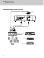
Preparations:
• Make sure that the power of the projector and that of the video equipment are turned off.
◆ Basic home theater system connection
Video player
DVD player
Set-top box or digital tuner
P
B
/C
B
(Blue)
P
R
/C
R
(Red)
Y (Green)
Connections5

11
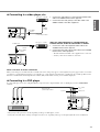
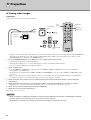
◆ Connecting to a video player, etc.
1. Connect one end (yellow) of a commercially available video
cable to the VIDEO terminal of this projector.
2. Connect the other end (yellow) of the video cable to the
VIDEO terminal of the video equipment.
When the video equipment is equipped with the
S-video terminal, make the connection as follows.
1. Connect one end of the supplied S-video cable to the
S-VIDEO terminal of this projector.
2. Connect the other end of the S-video cable to the S-VIDEO
terminal of the video equipment.
• Read the instruction manual of the equipment to be connected.
• Contact your dealer for details of connection.
When a TV tuner or VCR is connected:
When you use this projector with a TV tuner or VCR connected, no image may appear or a No Signal message may appear on the screen when
you change to a channel that is not being received. In this case, set the channels of the TV tuner or VCR again. To avoid this problem, use the
TV tuner or VCR with its channel skip function enabled. (Only channels that are being received will be displayed.)
◆ Connecting to a DVD player
To connect this projector to video equipment that has component video output terminals, such as a DVD player, use the COMPONENT
terminals.
• Images may not be projected correctly depending on the type of DVD player you use.
• It may take some time before an image is displayed on the screen, depending on the type of the input signal; this is not a malfunction.
1
2
Video player, or the like
To
VIDEO
terminal
Video cable
(commercially available)
To VIDEO
terminal
1
2
Video player, or the like
S-VIDEO cable
To S-VIDEO
terminal
To S-VIDEO
terminal
Component cable
(commercially available)
DVD player
P
R
/C
R
(Red)
P
B
/C
B
(Blue)
Y
(Green)
P
B
/C
B
(Blue)
P
R
/C
R
(Red)
Y (Green)

12
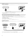
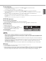
◆ DVI-D connections
You can project high-quality images by connecting the DVI terminal of this projector to video equipment having a DVI-D output terminal.
• For connection to the DVI terminal, use a commercially available DVI-D cable.
• Select DVI as the input source.
• Only RGB signals are supported. Component video signals are not supported.
When you connect this projector and a DVI-Digital device (such as a DVD player) via the DVI terminal, black
color may appear light and pale, depending on the type of the connected device.
• This depends on the black level setting of the connected device. There are two kinds of methods to digitally transfer image data, in which
different black level settings are employed respectively. Therefore, the specifications of the signals output from DVD players differ,
depending on the type of the digital data transfer method they use.
• Some DVD players are provided with a function to switch the methods to output DVI-Digital signals. When your DVD player is provided
with such function, set it as follows:
NORMAL ➜ EXPAND or ENHANCED
• Refer to the users guide of your DVD player for details.
• When your DVD player does not have such function, set BRIGHTNESS of this projector to -16.
◆ D-SUB connections
You can project high-quality images by connecting the D-SUB terminal of this projector to video equipment having a D-SUB output or BNC
terminal.
• For a connection from to the D-SUB terminal of this projector, use the supplied RGB cable.
• For video equipment with a BNC terminal, use a commercially available BNC to D-SUB cable to connect to this projector.
Equipment having a DVI-D terminal
To DVI-D terminal
DVI-D cable (commercially available)
To DVI terminal
Equipment having a D-SUB terminalEquipment having a BNC terminal
To D-SUB terminalTo BNC terminal
RGB cable
BNC to D-SUB cable (commercially available)
To D-SUB terminal

13
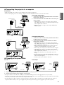
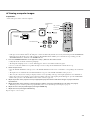
◆ Connecting the projector to a computer
Preparation:
• Make sure that the power of the projector and that of the computer are turned off.
• When connecting the projector to a desktop computer, disconnect the RGB cable that is connected to the monitor.
For analog connections:
1. Connect one end of the supplied RGB cable to the D-SUB
terminal of this projector.
2. Connect the other end of the RGB cable to the monitor port
of the computer.
• Additional devices, such as a conversion connector and an
analog RGB output adapter, are required depending on the type
of the computer to be connected.
• This projector does not support 3-line signals (SYNC-ON-
GREEN signals).
For digital connections:
1. Connect one end of a commercially available DVI-D cable to
the DVI terminal of this projector.
2. Connect the other end of the DVI-D cable to the DVI-D
terminal of the computer.
• Additional devices, such as a conversion connector and an
analog RGB output adapter, are required depending on the type
of the computer to be connected.
• When viewing images being input from a digital-connected
computer, press the DVI button on the remote control.
• Turn on the power of the projector before that of the computer.
• Additional devices, such as a conversion connector and an
analog RGB output adapter, are required depending on the type
of the computer to be connected.
• Using a long cable may decrease the quality of projected
images.
• Read the instruction manual of the equipment to be connected.
• Images may not be projected correctly, depending on the type
of the connected computer.
• Contact your dealer for details of connection.
◆ Plugging in the power cable
For US For Europe
1. Plug the supplied power cable into the power cable inlet of this projector.
2. Plug the other end of the power cable into a power outlet.
• The power cables for use in the U.S. and Europe are included with this projector. Use the appropriate one for your country.
• This projector uses the power plug of three-pin grounding type. Do not take away the grounding pin from the power plug. If the power plug
doesn’t fit your wall outlet, ask an electrician to change the wall outlet.
• The provided power cable for the U.S. is rated at 120 V. Never connect this cable to any outlet or power supply using other voltages or
frequencies than rated. If you use a power supply using other voltage than rated, prepare an appropriate power cable separately.
2
1
To D-SUB terminal
To monitor port
RGB cable
2
1
To DVI-D
terminal
DVI-D cable
(commercially
available)
To DVI terminal
2
1
Earthing
terminal
Power cable
1
2
Power cable
Earthing
terminal

14
◆ Viewing video images
Preparation:
• Turn on the power of the connected video equipment.
1. Confirm the POWER indicator lights up red.
• If the projector was turned off before the lamp was cooled down sufficiently last time, the fan may start rotating and the STANDBY/ON
button may not work after the power cable is plugged. (The STATUS indicator blinks green.) After the fan stops rotating, press the
STANDBY/ON button to turn back on the POWER indicator.
2. Press the STANDBY/ON button on the projector or ON ( I ) button on the remote control.
• It may take about one minute for the lamp to light up.
• The lamp fails to light up on rare occasions. If this happens, wait for a few minutes and then try again.
• Do not cover the lens with the lens cap while the lamp is on.
3. Select an input source.
• Press the VIDEO / S / COMP. button on the projector or the VIDEO, S-VIDEO or COMP. button on the remote control that is
corresponding to the terminal in use.
• The input source is switched between VIDEO, S-VIDEO and COMPONENT at every press of the VIDEO / S / COMP. button on the
projector.
• There may be a delay before an image is displayed on the screen, depending on the type of the input signal; this is not a malfunction.
• Some images become easier to view when the setting of aspect ratio is changed (see page 16).
4. Adjust the position of the projector to keep an appropriate projection distance with which images are projected in their
specified sizes.
5. Adjust the position of the projector so that the projector and the screen are perpendicular to each other (see page 8).
• When the projector cannot be positioned perpendicularly to the screen, adjust the projection angle (see page 8).
6. Adjust the size of the projected image by turning the ZOOM ring.
7. Adjust the focus by turning the FOCUS ring.
Repeat steps 4 to 7, if necessary.
Important
• When a 4:3 image is continuously displayed for a long time before displaying a 16:9 image, the afterimages of the black
bars may appear on the 16:9 image screen. Consult your dealer in this case.
• Do not display a still picture for a long time because the afterimages may persist on the screen.
STANDBY/ON
button
VIDEO/S/COMP.
button
FOCUS ring
ON (
I )
button
ZOOM ring
COMP. button
VIDEO button
S-VIDEO button
Projection6

15
To stop projecting:
1. Press the STANDBY/ON button on the projector or the STANDBY ( ) button on the remote control.
• A confirmation message is displayed.
• To cancel the procedure, wait a while or press the MENU button.
2. Press the STANDBY/ON button on the projector or the STANDBY ( ) button on the remote control again.
• The lamp goes out and the projector goes into a cooling period. In this condition, the POWER indicator turns red and the STATUS
indicator blinks green.
3. Wait about one minute for the STATUS indicator to be off and the POWER indicator to be steadily lit in red.
• During this one minute period, the intake fan and exhaust fan rotate to cool the lamp.
• Do not unplug the power cable while the STATUS indicator is blinking. Unplugging the power cable immediately after use may cause a
breakdown.
• The fan may make loud sounds during cooling; this is not a malfunction.
KEYSTONE adjustment
With the control area of the projector:
1. Press the KEYSTONE (ENTER) button on the control area of the projector.
2. Equalize the widths at the top and bottom of the screen by pressing the or button, viewing the screen.
With the SETUP menu:
(See page 19 for menu setting.)
1. Display the SETUP menu.
2. Select KEYSTONE by pressing the or button.
3. Equalize the widths at the top and bottom of the screen by
pressing the or button, viewing the screen.
To cancel the menu:
4. Press the MENU button several times.
Important
• When the keystone adjustment is applied, the correct aspect ratio may not be obtained.
• When the keystone adjustment is applied, the resolution lowers. In addition, vertical stripes appear and straight lines bend
in images with complicated patterns. To prevent such symptoms, keep the screen and the projector perpendicular to each
other as much as possible.
• Though the projected image may be distorted momentarily when you change the setting value of the keystone adjustment,
such symptom is not a malfunction.
• Though the projected image may be distorted depending on the setting value of the keystone adjustment and the type of the
input signal, such symptom is not a malfunction. In such a case, adjust the setting value within the range where the
projected image is not distorted.
• The setting value displayed at the time of the keystone adjustment may vary depending on the type of the input signal.
IRIS button
Use to adjust the brightness and contrast of the image depending on the brightness level in the room.
1. Press the IRIS button on the remote control.
2. Adjusts the brightness and contrast of the image by pressing the or button, viewing the screen. Every time the button
is pressed, the image becomes brighter and more defined, suitable for TV viewing in a well-lit room. Every time the button
is pressed, the image becomes darker and the contrast is increased, suitable for watching movies in dim lighting.
SETUP
0
KEYSTONE
TV60

16
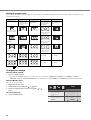
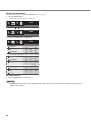
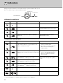
Setting the aspect ratio
You can change the aspect ratio of the input video signal (or the ratio of width to height of the image). Change the setting according to the type
of the input video signal.
Bold frames are recommended modes.
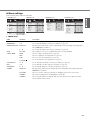
Changing the settings
With the remote control:
1. Press the ASPECT button.
• Every time the ASPECT button is pressed, the aspect mode changes from DEFAULT to NORMAL, to SQUEEZE, to ZOOM, to
THROUGH, and back to DEFAULT. DEFAULT is automatically set to either NORMAL or SQUEEZE depending on the input signal.
With the INITIAL menu:
(See page 19 for menu setting.)
1. Display the INITIAL menu.
2. Select ASPECT by pressing the or button.
3. Select your desired aspect ratio by pressing the or
button.
To cancel the menu:
4. Press the MENU button.
NORMAL SQUEEZE ZOOM THROUGH
Original image size Projects images with
an aspect ratio of 4:3
when the input signal
is 4:3 image.
Projects images with
an aspect ratio of
16:9.
Projects images in the
CinemaScope size or
Vista size together
with subtitles.
Projects images in
their original size as
input.
4:3 image (480i, 576i,
480p, 576p, and PC)
Available only when
the input signal is 480i,
576i, 480p or 576p.
4:3 CinemaScope and
Vista image
Available only when
the input signal is 480i,
576i, 480p or 576p.
Squeezed 4:3 (480i,
576i, 480p, 576p)
Available only when
the input signal is 480i,
576i, 480p or 576p.
16:9 image (1080i)
Not available. Not available.
16:9 image (720p)
Not available. Not available.
INITIAL
UPPER LEFT
AUTO
AUTO
DEFAULT
MENU POSITION
PROGRESSIVE
MODE
COLOR SYSTEM
ASPECT
TV60
Sidan laddas ...
Sidan laddas ...
Sidan laddas ...
Sidan laddas ...
Sidan laddas ...
Sidan laddas ...
Sidan laddas ...
Sidan laddas ...
Sidan laddas ...
Sidan laddas ...
Sidan laddas ...
Sidan laddas ...
Sidan laddas ...
Sidan laddas ...
Sidan laddas ...
Sidan laddas ...
Sidan laddas ...
Sidan laddas ...
Sidan laddas ...
Sidan laddas ...
Sidan laddas ...
Sidan laddas ...
-
 1
1
-
 2
2
-
 3
3
-
 4
4
-
 5
5
-
 6
6
-
 7
7
-
 8
8
-
 9
9
-
 10
10
-
 11
11
-
 12
12
-
 13
13
-
 14
14
-
 15
15
-
 16
16
-
 17
17
-
 18
18
-
 19
19
-
 20
20
-
 21
21
-
 22
22
-
 23
23
-
 24
24
-
 25
25
-
 26
26
-
 27
27
-
 28
28
-
 29
29
-
 30
30
-
 31
31
-
 32
32
-
 33
33
-
 34
34
-
 35
35
-
 36
36
-
 37
37
-
 38
38
-
 39
39
-
 40
40
-
 41
41
-
 42
42


Yamaha DPX-530 Bruksanvisning
- Kategori
- Projektorer
- Typ
- Bruksanvisning
på andra språk
- italiano: Yamaha DPX-530 Manuale del proprietario
- čeština: Yamaha DPX-530 Návod k obsluze
- español: Yamaha DPX-530 El manual del propietario
- Deutsch: Yamaha DPX-530 Bedienungsanleitung
- polski: Yamaha DPX-530 Instrukcja obsługi
- português: Yamaha DPX-530 Manual do proprietário
- français: Yamaha DPX-530 Le manuel du propriétaire
- Türkçe: Yamaha DPX-530 El kitabı
- English: Yamaha DPX-530 Owner's manual
- dansk: Yamaha DPX-530 Brugervejledning
- русский: Yamaha DPX-530 Инструкция по применению
- suomi: Yamaha DPX-530 Omistajan opas
- Nederlands: Yamaha DPX-530 de handleiding
- română: Yamaha DPX-530 Manualul proprietarului
Relaterade papper
Andra dokument
-
Samsung SP-LSP9TFA Användarmanual
-
-
Sharp ANSV100T Bruksanvisningar
-
Silvercrest SKT 2300 A1 - IAN 54346 Bruksanvisning
-
Christie LW41 Användarmanual
-
Silvercrest 113364 Operating Instructions Manual
-
König ANT-UHF70-KN Användarmanual
-
 Vexve AM40 Instructions & User's Manual
-
Sony VPL-GTZ380 Användarmanual
-
3M 78-9236-6824-4 - Digital Projector X80 XGA LCD Safety Manual
