Emerson R412013605-BAL-001-AD Användarmanual
- Typ
- Användarmanual

Betriebsanleitung | Operating instructions | Notice d’instruction
Istruzioni per l'uso | Instrucciones de servicio | Bruksanvisning
R412013605-BAL-001-AD
2022-02; Replaces: 2017-06
DE/EN/FR/IT/ES/SV
AVENTICS™ PROFINET
Buskoppler mit Linkstruktur DDL
Bus coupler with link structure DDL
Coupleur de bus avec structure de liens DDL
Accoppiatore bus con sistema di collegamentoDDL
Acoplador de bus con estructura de enlace DDL
Fältbussnod med länkstruktur DDL

AVENTICS™ PROFINET | R412013605-BAL-001-AD | Deutsch 2
Inhaltsverzeichnis
1 Zu dieser Dokumentation.................................................................................................................................................................................................. 3
1.1 Gültigkeit der Dokumentation .......................................................................................................................................................................................... 3
1.2 Erforderliche und ergänzende Dokumentationen ............................................................................................................................................................. 3
1.3 Darstellung von Informationen ......................................................................................................................................................................................... 3
1.3.1 Warnhinweise .................................................................................................................................................................................................... 3
1.3.2 Symbole............................................................................................................................................................................................................. 3
1.4 Abkürzungen .................................................................................................................................................................................................................... 3
2 Sicherheitshinweise........................................................................................................................................................................................................... 3
2.1 Zu diesem Kapitel ............................................................................................................................................................................................................. 3
2.2 Bestimmungsgemäße Verwendung.................................................................................................................................................................................. 3
2.3 Nicht bestimmungsgemäße Verwendung ........................................................................................................................................................................ 3
2.4 Qualifikation des Personals ............................................................................................................................................................................................... 3
2.5 Allgemeine Sicherheitshinweise........................................................................................................................................................................................ 3
2.6 Störung des Steuerungsnetzwerks.................................................................................................................................................................................... 4
2.7 Produkt- und technologieabhängige Sicherheitshinweise................................................................................................................................................. 4
3 Lieferumfang..................................................................................................................................................................................................................... 4
4 Zu diesem Produkt ............................................................................................................................................................................................................ 4
4.1 Leistungsbeschreibung ..................................................................................................................................................................................................... 4
4.2 Produktbeschreibung ....................................................................................................................................................................................................... 5
4.3 Identifikation des Produkts ............................................................................................................................................................................................... 5
5 Montage............................................................................................................................................................................................................................ 5
5.1 Produkt montieren............................................................................................................................................................................................................ 5
5.1.1 Abmessungen .................................................................................................................................................................................................... 5
5.2 Produkt elektrisch anschließen ......................................................................................................................................................................................... 5
5.2.1 DDL und Buskoppler anschließen ....................................................................................................................................................................... 5
5.2.2 Versorgungsspannung anschließen.................................................................................................................................................................... 5
6 Inbetriebnahme................................................................................................................................................................................................................. 6
6.1 Erstmalige Inbetriebnahme............................................................................................................................................................................................... 6
6.1.1 Voreinstellungen vornehmen............................................................................................................................................................................. 6
6.2 PROFINET-Schnittstelle starten ......................................................................................................................................................................................... 6
6.3 VS mit Buskoppler in Betrieb nehmen ............................................................................................................................................................................... 7
6.3.1 Hochlaufverhalten.............................................................................................................................................................................................. 7
7 Im Betrieb.......................................................................................................................................................................................................................... 7
7.1 Diagnose........................................................................................................................................................................................................................... 7
7.1.1 LED-Diagnose..................................................................................................................................................................................................... 7
7.1.2 Software-Diagnose............................................................................................................................................................................................. 7
8 Demontage und Austausch................................................................................................................................................................................................ 8
8.1 Buskoppler demontieren .................................................................................................................................................................................................. 8
9 Entsorgung........................................................................................................................................................................................................................ 8
10 Instandhaltung und Instandsetzung .................................................................................................................................................................................. 8
10.1 Reinigung und Pflege........................................................................................................................................................................................................ 8
10.2 Wartung ........................................................................................................................................................................................................................... 8
11 Fehlersuche und Fehlerbehebung...................................................................................................................................................................................... 8
12 Technische Daten .............................................................................................................................................................................................................. 8
13 Anhang.............................................................................................................................................................................................................................. 8
13.1 PROFINET-Konfiguration................................................................................................................................................................................................... 8
13.2 DDL-Teilnehmer – Parameter............................................................................................................................................................................................ 9
13.3 PROFINET Diagnose Alarme .............................................................................................................................................................................................. 9
13.4 Datenleitung DDL ............................................................................................................................................................................................................. 9
13.5 PROFINET – Unterstützte Funktionen................................................................................................................................................................................ 9

1 Zu dieser Dokumentation
1.1 Gültigkeit der Dokumentation
Diese Dokumentation enthält wichtige Informationen, um das Produkt sicher
und sachgerecht zu montieren, zu bedienen, zu warten und einfache Störungen
selbst zu beseitigen.
uLesen Sie beide Anleitungen vollständig und insbesondere das Kapitel g2.Si-
cherheitshinweise, bevor Sie mit dem Produkt arbeiten.
1.2 Erforderliche und ergänzende Dokumentationen
uNehmen Sie das Produkt erst in Betrieb, wenn Ihnen folgende Dokumentatio-
nen vorliegen und Sie diese verstanden und beachtet haben.
Erforderliche und ergänzende Dokumentationen
Titel Dokumentnummer Dokumentart
DDL-Systembeschreibung R499050030 Betriebsanleitung
Anlagendokumentation
Weitere Angaben zu Komponenten entnehmen Sie dem Online-Katalog.
1.3 Darstellung von Informationen
1.3.1 Warnhinweise
In dieser Dokumentation stehen Warnhinweise vor einer Handlungsabfolge, bei
der die Gefahr von Personen- oder Sachschäden besteht. Die beschriebenen
Maßnahmen zur Gefahrenabwehr müssen eingehalten werden.
Aufbau von Warnhinweisen
SIGNALWORT
Art und Quelle der Gefahr
Folgen bei Nichtbeachtung
uMaßnahmen zur Gefahrenabwehr
Bedeutung der Signalwörter
GEFAHR
Unmittelbar drohende Gefahr für das Leben und die Gesundheit von Personen.
Das Nichtbeachten dieser Hinweise hat schwere gesundheitliche Auswirkun-
gen zur Folge, bis hin zum Tod.
WARNUNG
Möglicherweise drohende Gefahr für das Leben und die Gesundheit von Perso-
nen.
Das Nichtbeachten dieser Hinweise kann schwere gesundheitliche Auswirkun-
gen zur Folge haben, bis hin zum Tod.
VORSICHT
Möglicherweise gefährliche Situation.
Das Nichtbeachten dieser Hinweise kann leichte Verletzungen zur Folge haben
oder zu Sachbeschädigungen führen.
ACHTUNG
Möglichkeit von Sachbeschädigungen oder Funktionsstörungen.
Das Nichtbeachten dieser Hinweise kann Sachbeschädigungen oder Funktions-
störungen zur Folge haben, jedoch keine Personenschäden.
1.3.2 Symbole
Empfehlung für den optimalen Einsatz unserer Produkte.
Beachten Sie diese Informationen, um einen möglichst reibungslosen
Betriebsablauf zu gewährleisten.
1.4 Abkürzungen
In dieser Dokumentation werden folgende Abkürzungen verwendet:
Tab.1: Abkürzungen
Abkürzung Bedeutung
VS Ventilsystem
DDL Drive & Diagnostic Link
FE Funktionserde (Functional Earth)
2 Sicherheitshinweise
2.1 Zu diesem Kapitel
Das Produkt wurde gemäß den allgemein anerkannten Regeln der Technik her-
gestellt. Trotzdem besteht die Gefahr von Personen- und Sachschäden, wenn Sie
dieses Kapitel und die Sicherheitshinweise in dieser Dokumentation nicht beach-
ten.
1. Lesen Sie diese Dokumentation gründlich und vollständig, bevor Sie mit dem
Produkt arbeiten.
2. Bewahren Sie die Dokumentation so auf, dass sie jederzeit für alle Benutzer
zugänglich ist.
3. Geben Sie das Produkt an Dritte stets zusammen mit der erforderlichen Doku-
mentation weiter.
2.2 Bestimmungsgemäße Verwendung
Bei dem Produkt handelt es sich um eine elektrische Anlagenkomponente.
Sie dürfen das Produkt wie folgt einsetzen:
1. ausschließlich im industriellen Bereich.
2. unter Einhaltung der in den technischen Daten genannten Leistungsgrenzen.
Das Produkt ist für den professionellen Gebrauch und nicht für die private Ver-
wendung bestimmt.
Die bestimmungsgemäße Verwendung schließt auch ein, dass Sie diese Anlei-
tung, insbesondere das Kapitel g2.Sicherheitshinweise, und die Anleitung DDL-
Systembeschreibung R499050030 gelesen und verstanden haben.
2.3 Nicht bestimmungsgemäße Verwendung
Jeder andere Gebrauch als in der bestimmungsgemäßen Verwendung beschrie-
ben ist nicht bestimmungsgemäß und deshalb unzulässig.
Wenn ungeeignete Produkte in sicherheitsrelevanten Anwendungen eingebaut
oder verwendet werden, können unbeabsichtigte Betriebszustände in der An-
wendung auftreten, die Personen- und/oder Sachschäden verursachen können.
Setzen Sie daher ein Produkt nur dann in sicherheitsrelevanten Anwendungen
ein, wenn diese Verwendung ausdrücklich in der Dokumentation des Produkts
spezifiziert und erlaubt ist. Beispielsweise in Ex-Schutz Bereichen oder in sicher-
heitsbezogenen Teilen einer Steuerung (funktionale Sicherheit).
Für Schäden bei nicht bestimmungsgemäßer Verwendung übernimmt die
AVENTICS GmbH keine Haftung. Die Risiken bei nicht bestimmungsgemäßer
Verwendung liegen allein beim Benutzer.
Zur nicht bestimmungsgemäßen Verwendung des Produkts gehört:
• außerhalb der Anwendungsgebiete verwenden, die in dieser Anleitung ge-
nannt werden.
• unter Betriebsbedingungen verwenden, die von den in dieser Anleitung oder
in der DDL-Systembeschreibung (R499050030) beschriebenen abweichen.
2.4 Qualifikation des Personals
Die in dieser Dokumentation beschriebenen Tätigkeiten erfordern grundlegende
Kenntnisse der Elektrik und Pneumatik sowie Kenntnisse der zugehörigen Fach-
begriffe. Um die sichere Verwendung zu gewährleisten, dürfen diese Tätigkeiten
daher nur von einer entsprechenden Fachkraft oder einer unterwiesenen Person
unter Leitung einer Fachkraft durchgeführt werden.
Eine Fachkraft ist, wer aufgrund seiner fachlichen Ausbildung, seiner Kenntnisse
und Erfahrungen sowie seiner Kenntnisse der einschlägigen Bestimmungen die
ihm übertragenen Arbeiten beurteilen, mögliche Gefahren erkennen und geeig-
nete Sicherheitsmaßnahmen treffen kann. Eine Fachkraft muss die einschlägigen
fachspezifischen Regeln einhalten.
2.5 Allgemeine Sicherheitshinweise
Allgemeine Hinweise
• Beachten Sie die gültigen Vorschriften zur Unfallverhütung und zum Umwelt-
schutz.
AVENTICS™ PROFINET | R412013605-BAL-001-AD | Deutsch 3

• Beachten Sie die Sicherheitsvorschriften und -bestimmungen des Landes, in
dem das Produkt eingesetzt/angewendet wird.
• Verwenden Sie AVENTICS-Produkte nur in technisch einwandfreiem Zustand.
• Beachten Sie alle Hinweise auf dem Produkt.
• Personen, die AVENTICS-Produkte montieren, bedienen, demontieren oder
warten dürfen nicht unter dem Einfluss von Alkohol, sonstigen Drogen oder
Medikamenten, die die Reaktionsfähigkeit beeinflussen, stehen.
• Verwenden Sie nur vom Hersteller zugelassene Zubehör- und Ersatzteile, um
Personengefährdungen wegen nicht geeigneter Ersatzteile auszuschließen.
• Halten Sie die in der Produktdokumentation angegebenen technischen Daten
und Umgebungsbedingungen ein.
• Wenn in sicherheitsrelevanten Anwendungen ungeeignete Produkte einge-
baut oder verwendet werden, können unbeabsichtigte Betriebszustände in
der Anwendung auftreten, die Personen- und/oder Sachschäden verursachen
können. Setzen Sie daher ein Produkt nur dann in sicherheitsrelevante Anwen-
dungen ein, wenn diese Verwendung ausdrücklich in der Dokumentation des
Produkts spezifiziert und erlaubt ist.
• Sie dürfen das Produkt erst dann in Betrieb nehmen, wenn festgestellt wurde,
dass das Endprodukt (beispielsweise eine Maschine oder Anlage), in das die
AVENTICS-Produkte eingebaut sind, den länderspezifischen Bestimmungen,
Sicherheitsvorschriften und Normen der Anwendung entspricht.
• Sie dürfen das Gerät grundsätzlich nicht verändern oder umbauen.
• Verwenden Sie das Gerät ausschließlich im Leistungsbereich, der in den tech-
nischen Daten angegeben ist.
• Belasten Sie das Gerät unter keinen Umständen mechanisch. Stellen Sie keine
Gegenstände darauf ab.
• Die Gewährleistung gilt nur bei bestimmungsgemäßer Verwendung.
• Beachten Sie weiterführende Sicherheitshinweise in der Betriebsanleitung.
Transport und Lagerung
• Der einwandfreie und sichere Betrieb der Geräte setzt einen sachgemäßen
Transport, fachgerechte Lagerung, Aufstellung und Montage voraus.
Bei der Reinigung
• Reinigen Sie das Gerät ausschließlich mit einem leicht feuchten Tuch. Ver-
wenden Sie dazu ausschließlich Wasser und ggf. ein mildes Reinigungsmittel.
2.6 Störung des Steuerungsnetzwerks
Produkte mit Ethernet-Anschluss sind für den Einsatz in speziellen industriellen
Steuerungsnetzwerken ausgelegt. Folgende Sicherheitsmaßnahmen einhalten:
• Immer bewährte branchenübliche Vorgehensweisen zur Netzwerksegmentie-
rung befolgen.
• Direkte Anbindung von Produkten mit Ethernet-Anschluss an das Internet ver-
hindern.
• Sicherstellen, dass Gefährdungen durch das Internet und das Unternehmens-
netzwerk für alle Steuerungssystemgeräte und/oder Steuerungssysteme mi-
nimiert werden.
• Sicherstellen, dass Produkte, Steuerungssystemgeräte und/oder Steuerungs-
systeme nicht über das Internet zugänglich sind.
• Steuerungsnetzwerke und Remotegeräte hinter Firewalls verlegen und vom
Unternehmensnetzwerk isolieren.
• Wenn ein Remotezugriff erforderlich ist, ausschließlich sichere Methoden wie
virtuelle private Netzwerke (VPNs) verwenden.
ACHTUNG! VPNs, Firewalls und andere softwarebasierte Produkte können Si-
cherheitslücken aufweisen. Die Sicherheit der VPN-Nutzung kann nur so hoch
sein wie die Sicherheit der angeschlossenen Geräte. Daher immer die aktuelle
Version des VPNs, der Firewall und anderer softwarebasierter Produkte ver-
wenden.
• Sicherstellen, dass die neueste freigegebene Software- und Firmware-Version
auf allen mit dem Netz verbundenen Produkten installiert sind.
2.7 Produkt- und technologieabhängige Sicherheitshinweise
Vor der Montage
• Der Buskoppler (elektrostatisch gefährdete Bauelemente) darf nur durch ge-
schultes Personal geöffnet werden.
• Schalten Sie immer den relevanten Anlagenteil drucklos und spannungsfrei,
bevor Sie das Gerät montieren bzw. Stecker anschließen oder ziehen. Sichern
Sie die Anlage gegen Wiedereinschalten.
• Die Versorgungsspannung muss aus einem Netzteil mit sicherer Trennung
nach DINEN60742, Klassifikation VDE0551 erfolgen. Achten Sie bei den Ge-
räten auf eine der Beschreibung gemäße externe Absicherung.
• Die Gewährleistung erlischt bei fehlerhafter Montage.
Bei der Montage
• Montieren Sie den Buskoppler immer auf eine Montageplatte oder in einem
Schaltschrank.
• Beachten Sie die Einbaulage laut der Betriebsanleitung.
• Verlegen Sie die Leitungen so, dass niemand darüber stolpern kann.
• Wenn das Gerät nicht ordnungsgemäß befestigt ist, können andere Anlagen-
teile durch unkontrollierte Bewegungen des Geräts beschädigt werden. Stel-
len Sie sicher, dass das Gerät sicher befestigt ist.
• Erden Sie die Geräte je nach Landesvorschrift.
• Verwenden Sie nur Leitungen, die in den Betriebsanleitungen oder Angebots-
zeichnungen angegeben sind.
Inbetriebnahme
• Die Installation/Montage und Inbetriebnahme des Gerätes darf nur im span-
nungsfreien und drucklosen Zustand und nur durch geschultes und entspre-
chend qualifiziertes Fachpersonal erfolgen.
• Nehmen Sie das Gerät nur in Betrieb, wenn es komplett montiert, korrekt ver-
drahtet und getestet wurde.
• Schalten Sie die Betriebsspannung aus, bevor Sie Stecker verbinden oder tren-
nen, um Schäden an der Elektrik zu vermeiden.
Im Betrieb
• Beachten Sie weiterführende Sicherheitshinweise in der Betriebsanleitung.
3 Lieferumfang
• 1x Buskoppler PROFINET DDL
• 1x Betriebsanleitung
4 Zu diesem Produkt
4.1 Leistungsbeschreibung
Der Buskoppler dient zur Anbindung des DDL-Systems an den Feldbus PROFINET.
Der Buskoppler kommuniziert mit dem Feldbussystem und kontrolliert den DDL
(Drive & Diagnostic Link).
Der Buskoppler ist ausschließlich für den Betrieb als Device an einem Bussystem
PROFINET bestimmt.
Der Buskoppler ist ein modulares EA-Gerät („Modular IO Device“) entsprechend
der PROFINET-Spezifikation.
Der Buskoppler verbindet die lokalen EA-Geräte mit dem PROFINET-Netzwerk. Im
Datenmodell sind diese EA-Geräte modular an den Buskoppler angeschlossen.
Dabei funktioniert der Buskoppler wie eine Schnittstelle zwischen dem PROFI-
NET-Netzwerk und den lokalen DDL-Teilnehmern.
AVENTICS™ PROFINET | R412013605-BAL-001-AD | Deutsch 4

4.2 Produktbeschreibung
X7E1
X7E2
XPD
X1S
SF
BF
DDL PROFINET
1
2
3
4
5
6
Abb.1: Produktübersicht
1 PROFINET-LEDs 2 X7E2: PROFINET IN
3 X7E1: PROFINET OUT 4 XPD: DDL-Verbindung
5 X1S: M12 -Spannungsversorgung
(Einbaustecker X1S Power Supply)
6 S1/S2
4.3 Identifikation des Produkts
Beachten Sie die Produktangaben auf dem Produkt und der Verpackung.
5 Montage
VORSICHT
Verletzungsgefahr durch Montage unter Druck oder Spannung!
Die Montage unter Druck oder anliegender elektrischer Spannung kann zu Ver-
letzungen führen und das Produkt oder Anlagenteile beschädigen.
1. Schalten Sie den relevanten Anlagenteil drucklos und spannungsfrei, bevor
Sie das Produkt montieren.
2. Sichern Sie die Anlage gegen Wiedereinschalten.
5.1 Produkt montieren
VORSICHT
Verletzungsgefahr durch fehlerhafte Montage!
Fehlerhafte Montage kann zu unkontrollierten Bewegungen des Produkts oder
der Anlage führen.
1. Stellen Sie sicher, dass der Buskoppler korrekt befestigt ist.
2. Stellen Sie sicher, dass das Gerät sicher und mit den richtigen Anzugsmo-
menten befestigt ist.
1. Lassen Sie den Buskoppler vor dem Einbau einige Stunden akklimatisieren, da
sich sonst im Gehäuse Kondenswasser niederschlagen kann.
2. Schalten Sie den relevanten Anlagenteil spannungsfrei und drucklos.
3. Entfernen Sie die vier Befestigungsschrauben.
4. Setzen Sie den Buskoppler an der gewünschten Stelle auf die Montageplatte
(beliebig)/Schaltschrank (seitlich) auf.
5. Ziehen Sie die vier Befestigungsschrauben M5 an (Anzugsmoment:6Nm).
5.1.1 Abmessungen
10
21,4 30
34,5
1515
5,5
6060
3,5
120
40,6
60,3
79,8
84,5
106,5
49,5
140
120,5
13
45
50
1) 4)3)2)
Abb.2: Buskoppler, Abmessungen
5.2 Produkt elektrisch anschließen
5.2.1 DDL und Buskoppler anschließen
Die elektrischen Anschlüsse des Buskopplers werden über verschraubte Rund-
steckverbinder M12x1 hergestellt.
uVerbinden Sie die Anschlüsse mit dem Buskoppler.
ACHTUNG
Sachschaden durch eindringende Flüssigkeiten und Fremdkörper!
Flüssigkeiten und Fremdkörper können durch fehlende Dichtungen und Ver-
schlüsse in die Steckverbindungen eindringen und das Produkt oder Anlagen-
teile beschädigen.
1. Verwenden Sie Rundsteckverbindungen der Schutzklasse IP65 oder besser.
2. Stellen Sie sicher, dass die Dichtungen im Stecker vorhanden sind und nicht
beschädigt sind.
3. Verschließen Sie alle nicht benutzten Steckverbinder mit Verschlusskappen
(Blindsteckern).
4. Stellen Sie vor der Inbetriebnahme sicher, dass alle Stecker richtig ange-
schlossen sind.
Eine Funktionserde wird über den Anschluss X1S angeschlossen. Siehe
gTab.2.
5.2.2 Versorgungsspannung anschließen
X7E1
X7E2
XPD
X1S
4
1
2
3
Abb.3: Anschlüsse und Stecker
1 X7E2, PROFINET 2 X7E1, PROFINET
3 XPD 4 Einbaustecker X1S POWER SUPPLY
Über den Einbaustecker X1S POWER SUPPLY (4) werden die Ventilspulen mit
Spannung versorgt.
AVENTICS™ PROFINET | R412013605-BAL-001-AD | Deutsch 5

1
2
3 4
Abb.4: POWER X1S
Tab.2: Pinbelegung X1S
Kontakt Pinbelegung
Pin 1 24V Elektronik
Pin 2 24V Ventile
Pin 3 0V (max. 4A)
Pin 4 FE
Über X1S, Pin 1 werden die Elektronik des Buskopplers und die Elektronik aller
über das DDL angeschlossenen I/O-Module und Initiatoren versorgt (bei Modulen
ohne externe Spannungseinspeisung).
Über X1S, Pin 2 muss bei Verwendung von Modulen ohne externe Spannungsver-
sorgung die Schaltspannung für die angeschlossenen Ventile eingespeist wer-
den.
Durch die getrennte Einspeisung der Versorgungsspannungen über
Pin 1 und Pin 2 ist es in einer NOT-AUS-Situation möglich, nur die Ven-
tile abzuschalten, während die SPS, die seriellen Schnittstellen und die
Initiatoren in Betrieb bleiben. Ein Abschalten der Versorgungsspan-
nung für die serielle Schnittstelle kann bei der SPS den Zustand STOP
bewirken.
ACHTUNG
Sachschaden durch Montage oder Demontage unter anliegender Span-
nung/Last!
Unkontrolliertes Trennen und Verbinden unter Spannung/Last kann das Pro-
dukt oder Anlagenteile beschädigen.
uSchalten Sie vor dem Verbinden oder Trennen der Steckverbinder die rele-
vanten Anlagenteile spannungsfrei.
• Verwenden Sie nur 4-polige M12-Anschlussbuchsen, bei denen Pin5 ver-
schlossen ist, um eine Vertauschung mit anderen Anschlüssen auszuschlie-
ßen.
• Achten Sie darauf, dass der Anschlussquerschnitt größtmöglich gewählt wird,
aber mindestens 0,55mm² betragt.
• Sichern Sie beide Versorgungsspannungen mit externen 3-A-T-Sicherungen.
Die anliegende Versorgungsspannung wird durch eine grüne LED (5V)
angezeigt: Die LED leuchtet grün, sobald die Elektronikspannung
>18V ist. Siehe gTab.5.
Der maximal zugelassene Strom in der 0-V-Leitung ist auf 4A durch
den Steckverbinder beschränkt.
Die 24-V-Versorgungen müssen aus einem gemeinsamen Netzteil
bzw. mit gemeinsamer 0-V-Verbindung erfolgen. Es muss sich um ein
Netzteil mit sicherer Trennung nach DINEN60742, Klassifikation
VDE0551 handeln.
6 Inbetriebnahme
Der Buskoppler darf nur in Verbindung mit der Gesamtanlage, in die er eingebaut
ist, in Betrieb genommen werden.
uWenden Sie sich an den Anlagenhersteller, wenn Sie den Buskoppler in Be-
trieb nehmen wollen.
6.1 Erstmalige Inbetriebnahme
ACHTUNG
Sachschäden durch unkontrollierte Bewegungen des Geräts!
Durch unkontrollierte Bewegungen kann der Buskoppler und andere Anlagen-
teile beschädigt werden.
uFühren Sie die Inbetriebnahme des Buskopplers nur im drucklosen Zustand
durch.
6.1.1 Voreinstellungen vornehmen
Folgende Voraussetzungen müssen erfüllt sein:
• Die Übertragungsrate muss eingestellt sein (an allen DDL-Modulen gleich).
• Die Adressierungsbedingungen des DDL (Drive & Diagnostic Link) müssen er-
füllt sein.
• Die DDL-Konfiguration muss eingestellt und geprüft sein.
• Der Abschlusswiderstand hinter dem letzten DDL-Teilnehmer muss ange-
schlossen sein.
DDL-Adresse einstellen
Am Buskoppler muss keine DDL-Adresse eingestellt werden.
Zur korrekten Funktion des DDL (Drive & Diagnostic Link) müssen folgende
Adressierungsbedingungen erfüllt sein:
• DDL-Adresse zwischen 1-14, bei 1 beginnend, ohne Lücken, Adresse nicht
doppelt vergeben
DDL-Adresse0: siehe DDL-Systembeschreibung (R499050030).
Übertragungsrate (DDL-Modus) einstellen
Die Übertragungsrate des DDL wird mit dem 5-poligen Dip-Schalter S2 auf der
Vorderseite festgelegt. Alle DDL-Teilnehmer müssen auf die gleiche Übertra-
gungsrate eingestellt werden.
1
ON ONAPEMs APEMs
234 12345
S2.1-S2.5
S1.1-S1.4
S1
S2
Abb.5: DIP-Schalter S2
Tab.3: DDL-Baudrate
Schalter Bit Open On
S2 (5bit) 5 DDL 125 kBaud DDL 250kBaud (default)
Die Übertragungsrate kann wie folgt eingestellt werden:
1. Öffnen Sie die Abdeckung des Dip-Schalters S2.
2. Bringen Sie den Dip-Schalter S2.5 in die gewünschte Position. Siehe gAbb.5.
3. Schließen Sie die Abdeckung des Dip-Schalters S2.
Buskoppler konfigurieren
Siehe Kapitel g13.2.DDL-Teilnehmer – Parameter.
6.2 PROFINET-Schnittstelle starten
Der Anschluss an das Bussystem wird über die DatensteckerM12, 5-polig, D-co-
diert ausgeführt. Die physikalische Reihenfolge der Geräte in einem PROFINET-
System kann beliebig gewählt werden. Die Anschlüsse X7E1, PROFINET (2) und
X7E2, PROFINET (1), sind daher vertauschbar und können nur außerhalb des Be-
triebs konfiguriert werden. Siehe gAbb.3.
2
1
43
43
52
15
BUS IN
X7E1
Abb.6: X7E1-BUS IN
43
2
15
X7E2
BUS OUT
Abb.7: X7ES-BUS OUT
Tab.4: Pinbelegung, Datenstecker M12, D-codiert
Kontakt Pinbelegung
Pin 1 TD +
Pin 2 RD +
AVENTICS™ PROFINET | R412013605-BAL-001-AD | Deutsch 6

Kontakt Pinbelegung
Pin 3 TD -
Pin 4 RD -
Pin 5 nicht belegt
6.3 VS mit Buskoppler in Betrieb nehmen
Bevor Sie das System in Betrieb nehmen, müssen Sie folgende Arbeiten durchge-
führt und abgeschlossen haben:
• Sie haben das Ventilsystem und den Buskoppler montiert.
• Sie haben den Buskoppler angeschlossen.
Siehe Kapitel g5.2.Produkt elektrisch anschließen.
• Sie haben die Voreinstellungen und die Konfiguration durchgeführt.
Siehe Kapitel g6.1.1.Voreinstellungen vornehmen.
• Sie haben den Busmaster so konfiguriert, dass die Ventile richtig angesteuert
werden.
Die Inbetriebnahme und Bedienung darf nur von einer Elektro- oder
Pneumatikfachkraft oder von einer unterwiesenen Person unter der
Leitung und Aufsicht einer Fachkraft erfolgen. Siehe Kapitel
g2.4.Qualifikation des Personals.
VORSICHT
Unkontrollierte Bewegungen der Aktoren beim Einschalten der Pneumatik!
Es besteht Verletzungsgefahr, wenn sich das System in einem undefinierten
Zustand befindet.
1. Bringen Sie das System in einen definierten Zustand, bevor Sie es einschal-
ten!
2. Stellen Sie sicher, dass sich keine Person innerhalb des Gefahrenbereichs
befindet, wenn Sie die Druckluftversorgung einschalten.
3. Beachten Sie auch die entsprechenden Anweisungen und Warnhinweise
der Betriebsanleitung Ihres VS.
1. Schalten Sie die Betriebsspannung ein.
2. Überprüfen Sie die LED-Anzeigen an allen Modulen.
3. Schalten Sie die Druckluftversorgung ein.
6.3.1 Hochlaufverhalten
Das Hochlaufverfahren läuft wie folgt ab:
1. Der Buskoppler startet automatisch die Kommunikation mit den DDL-Modu-
len und stellt fest, welche Module vorhanden sind. Gleichzeitig teilt der PROFI-
NET Controller dem Buskoppler die in der Steuerung hinterlegte Konfigurati-
on mit.
2. Der Buskoppler überprüft die Konfiguration und gibt ggf. folgende Fehler zu-
rück:
– DDL Adresslücke
– kein DDL Modul angeschlossen
– weniger DDL Module angeschlossen als konfiguriert
– mehr DDL Module angeschlossen als konfiguriert
3. Wenn ein Fehler erkannt wird, wartet der Buskoppler 5Sekunden und startet
die DDL-Kommunikation erneut. Der Anwender kann währenddessen den
Adressfehler beheben. Siehe auch Kapitel g6.1.1.Voreinstellungen vorneh-
men. Die DDL LED bleibt im Fehlerfall rot. Ohne Fehler geht die LED aus. Siehe
Kapitel g13.2.DDL-Teilnehmer – Parameter. Der Buskoppler benutzt die ers-
te gültige Konfiguration. Nachfolgende Änderungen werden erst nach einem
Neustart übernommen.
4. Mit diesen Informationen werden die Slots und Subslots für PROFINET erstellt.
Danach wartet der Buskoppler auf die Parameter vom PROFINET Controller.
5. Anschließend starten der Buskoppler und PROFINET-Controller den zyklischen
Datenaustausch.
6. Im Falle eines Abbruchs auf PROFINET-Seite läuft der Buskoppler anschließend
wieder an, solange sich die Parameter nicht geändert haben, da der DDL Stack
nur einmal mit Parameterübertragung gestartet wird. Im Falle der Änderung
der Parametrierung ist der Buskoppler also auf jeden Fall neu zu starten.
7 Im Betrieb
Beachten Sie folgende Punkte für den Betrieb:
• Ändern Sie Schalter und Konfiguration nicht im laufenden Betrieb. Geänderte
Einstellungen werden erst gültig, wenn die Geräte erneut eingeschaltet wer-
den.
• Beachten Sie, dass über den Schirm keine durch Potentialunterschiede be-
dingten Ausgleichsströme fließen dürfen.
7.1 Diagnose
7.1.1 LED-Diagnose
BFSF
Auf der Gehäuseoberseite zeigen Leuchtdioden (LED) den Zustand der PROFI-
NET-Schnittstelle und der Spannungsversorgung an. Siehe auch Kapitel
g5.2.2.Versorgungsspannung anschließen.
Tab.5: Übersicht der PROFINET-LED-Anzeigen
Label links Label rechts Bedeutung
5V grün DDL rot 5V: leuchtet, wenn Versorgungsspannung >18V
DDL:
• Leuchtet bei Konfigurationsfehler (Adresse, Bau-
drate, Abschlusswiderstand)
• Leuchtet bei Initialisierung und blinkt nach erfolg-
reicher Initialisierung
• Aus bei DDL-Kommunikation
SF rot BF rot SF: System Failure (Fehler System)
BF: Bus Failure (Fehler Buskoppler)
LINK0 grün LINK0/ACT0: leuchtet, wenn ein Link besteht, blinkt
beim Senden und Empfangen von Daten
LINK1 grün LINK0/ACT1: leuchtet, wenn ein Link besteht, blinkt
beim Senden und Empfangen von Daten
Die Spannungsversorgung für Ventile wird am Buskoppler nicht über-
wacht.
7.1.2 Software-Diagnose
Der Buskoppler stellt Diagnosedaten zur Verfügung:
Detaillierte Informationen zum Diagnoseaufbau der einzelnen DDL-Teilnehmer
kann der Beschreibung der jeweiligen DDL-Teilnehmer entnommen werden.
Das Weiterleiten der Diagnose an die SPS kann mit dem Dip-Schalter S1.1 unter-
bunden werden.
S1.1 auf 0 Die Diagnosedaten werden nicht an die SPS gesendet (default).
S1.1 auf 1 Die Diagnosedaten werden an die SPS gesendet.
Warnungen werden selbstständig gelöscht, sobald die Ursache behoben ist. Es
kann immer nur eine Meldung dargestellt werden.
Bei Änderungen am DDL wird empfohlen, immer einen Spannungsre-
set durchzuführen.
AVENTICS™ PROFINET | R412013605-BAL-001-AD | Deutsch 7

8 Demontage und Austausch
8.1 Buskoppler demontieren
ACHTUNG
Sachschaden bei anliegender Spannung!
Unkontrolliertes Trennen von der Spannung kann das Produkt oder Anlagen-
teile beschädigen.
uSchalten Sie den relevanten Anlagenteil spannungsfrei, bevor Sie das Gerät
demontieren bzw. Stecker abziehen.
1. Schalten Sie die 24-V-DC-Elektronik- und Ventilversorgung ab.
2. Entfernen Sie die angeschlossenen Stecker.
3. Lösen Sie den Buskoppler von der Arbeitsfläche.
4. Entfernen Sie den Buskoppler.
9 Entsorgung
Entsorgen Sie das Produkt nach den Bestimmungen Ihres Landes.
10 Instandhaltung und Instandsetzung
10.1 Reinigung und Pflege
ACHTUNG
Beschädigung der Oberfläche durch Lösemittel und aggressive Reinigungs-
mittel!
Die Oberflächen und Dichtungen können durch Lösemittel oder aggressive
Reinigungsmittel beschädigt werden.
1. Verwenden Sie niemals Lösemittel oder aggressive Reinigungsmittel.
2. Reinigen Sie das Gerät ausschließlich mit einem leicht feuchten Tuch. Ver-
wenden Sie dazu nur Wasser und ggf. ein mildes Reinigungsmittel.
uÜberprüfen Sie, ob alle Dichtungen und Verschlüsse der Steckverbindungen
festsitzen, damit bei der Reinigung keine Feuchtigkeit in den Buskoppler ein-
dringen kann.
10.2 Wartung
Der Buskoppler ist wartungsfrei. Unter aggressiven Umgebungsbedingungen
können jedoch die Dichtungen des Buskopplers schneller altern. Defekte Dich-
tungen führen zu pneumatischen Leckagen und zum Verlust der Schutzklasse
IP65.
1. Überprüfen Sie regelmäßig, ob die Dichtungen am Buskoppler einwandfrei
sind. Legen Sie die Wartungsintervalle je nach Ihren Umgebungs-bedingun-
gen fest und tragen Sie diese in den anlagenspezifischen Wartungsplan ein.
2. Beachten Sie die anlagenspezifischen Wartungsintervalle.
11 Fehlersuche und Fehlerbehebung
Störung mögliche Ursache Abhilfe
LED 5V leuchtet nicht Keine Spannung vorhanden Spannungsversorgung am
Buskoppler prüfen.
Buskoppler defekt Buskoppler austauschen.
Falsch konfektioniertes oder
defektes Kabel
Geprüfte Kabel verwenden.
LED L1/A1 bzw. L2/A2 leuch-
tet nicht
Es besteht keine physische
Verbindung zwischen PROFI-
NET Controller und Buskopp-
ler.
Ethernetkabel und PROFINET-
Anschlüsse überprüfen.
LED DDL leuchtet dauerhaft Fehlerhafte DDL Konfigurati-
on
Kontrolle der Baudrate,
lückenlose Adressierung 1-x,
Abschlusswiderstand vorhan-
den.
LED SF leuchtet Diagnose ist eingeschaltet
und es liegt eine Diagnose an.
Diagnose an den Teilnehmern
kontrollieren.
Störung mögliche Ursache Abhilfe
LED BF leuchtet Konfiguration stimmt nicht
mit der angeschlossenen
Hardware überein.
Konfiguration der Hardware
angleichen.
Wenn Sie den Fehler nicht beheben können, wenden Sie sich an unsere Kontakt-
adresse (Kontaktdaten: siehe Rückseite).
12 Technische Daten
Allgemeine Daten
Abmessungen (Breite x Höhe x Tiefe) 50mm x 120,5mm x 106,5mm
Gewicht ca. 425g
Lagerbedingung <80% RH
relative Luftfeuchtigkeit 0…95%
Schutzart nach EN60529/IEC529 IP65 (nur in montiertem Zustand und mit al-
len montierten Steckern/mit verschlossenen
Leitungsdosen)
Versorgungsspannung Sensorspannung 24VDC ±20%)
Ventilspannung 24VDC (±10%)
Die Versorgungsspannung muss aus einem
Netzteil mit sicherer Trennung erfolgen.
Zulässige Oberwelligkeit 5%
Einbaulage beliebig
Absicherung der Spannung Ventile extern 3A T
Absicherung der Spannung Elektronik extern 3A T
Achtung: Maximaler Strom in der 0-V-Leitung max. 4A
Spannungsabfall intern 0,8V
Strombedarf Elektronik 90mA
Stromversorgung für Initiatoren max. 3A pro DDL-Strang
Stromversorgung für Ventile max. 3A pro DDL-Strang
Hochlaufzeit nach Einschalten der Versor-
gungsspannung
2s
Thermischer Anwendungsbereich +5°C…+50°C
Lagertemperatur -20°C…+70°C
Berücksichtigte Normen und Richtlinien 2004/108/EG „Elektromagnetische Verträg-
lichkeit“ (EMV-Richtlinie)
DIN EN 61000-6-2 „Elektromagnetische Ver-
träglichkeit“ (Störfestigkeit Industriebereich)
DIN EN 61000-6-4 „Elektromagnetische Ver-
träglichkeit“ (Störaussendung Industriebe-
reich)
DIN EN 60204-1 „Sicherheit von Maschinen -
Elektrische Ausrüstung von Maschinen - Teil
1: Allgemeine Anforderungen“
13 Anhang
13.1 PROFINET-Konfiguration
Für die SPS-Konfigurations-Software, z.B. S7Simatic Manager, sind ggf. die
GSDML-Dateien für den Buskoppler sowie jedes verwendete DDL-Modul notwen-
dig.
Das Datenmodell für den PROFINET DDL Buskoppler ist durch verschiedene Mo-
dule beschrieben. Jedes Modul (Nr. 1 bis max. 14) repräsentiert ein DDL-Modul
und enthält je ein Submodul für Input (Nr.1), Output (Nr.2) und Diagnose
(Nr.3). Diagnose-Alarme und Parameter sind dabei jeweils dem Diagnose-Sub-
modul zugeordnet.
Zusätzlich enthält Modul 0 die PROFINET-spezifischen Submodule für DAP, Devi-
ce und beide Ports. Submodul 1 (Device) enthält 4Byte Buskoppler-Diagnoseda-
ten (Lifesign, Fehlerbits und Anwesenheitsliste).
Da es mit einigen PROFINET-CPUs Kompatibilitäts-probleme gibt, lassen sich die
4 Byte Buskoppler-Diagnosedaten auch über einen 15. Teilnehmer (DDL Master
Diagnosis) abrufen. Dieser Teilnehmer lässt sich nur in Slot 15 positionieren.
AVENTICS™ PROFINET | R412013605-BAL-001-AD | Deutsch 8

Vor der eigentlichen Inbetriebnahme muss dem Buskoppler über
Ethernet (DCP) ein Gerätename zugewiesen werden, damit der PROFI-
NET-Controller eine Verbindung öffnen kann. Dieser Gerätename wird
im Flash-Speicher gespeichert. Im Auslieferungszustand ist dieser Ge-
rätename leer, wie es vom PROFINET-Standard vorgesehen ist.
Damit der Name vergeben werden kann, muss am Buskoppler eine
korrekte DDL-Konfiguration angeschlossen sein, so dass die DDL-LED
blinkt.
13.2 DDL-Teilnehmer – Parameter
Die Parameterbeschreibungen der einzelnen DDL-Teilnehmer sind den entspre-
chenden Betriebsanleitung zu entnehmen.
13.3 PROFINET Diagnose Alarme
Der Buskoppler ermöglicht es, Störungen an den PROFINET Controller zu melden.
Es wird „Extended Channel Diagnosis“ benutzt.
Alarme vom Buskoppler werden auf Slot0, Subslot1 ausgegeben. Diese können
sein:
• DDL Adresslücke
• kein DDL Modul angeschlossen
• weniger DDL Module angeschlossen als konfiguriert
• mehr DDL Module angeschlossen als konfiguriert
Außer bei der Meldung „keine DDL Module“ wird jeweils die Anwesenheitsliste
als zusätzlicher Parameter mit übertragen.
Zusätzlich wird das StdDiag-Byte von jedem angeschlossenen DDL-Modul über-
wacht und ggf. die Meldung:
• DDL Modul- StdDiag mit dem StdDiag-Byte als Parameter übertragen. Alle
diese Fehlermeldungen können gleichzeitig anliegen und werden jeweils ge-
löscht, wenn der Fehler behoben ist.
13.4 Datenleitung DDL
Der Ausgang des DDL ist auf allen Leitungen kurzschlussfest. Jedoch können DDL-
Teilnehmer beschädigt werden, wenn 24V an den Signalleitungen DDL H und
DDL L anliegen.
Aus diesem Grund wird empfohlen, vorkonfektionierte Kabel zu verwenden. Die
Belegung der DDL-Anschlüsse ist in der DDL-Systembeschreibung (R499050030)
beschrieben.
Der DDL-Abschlussstecker wird benötigt, falls das Modul der letzte bzw. einzige
Teilnehmer eines DDL-Strangs ist. Damit ist ein definierter Leitungsabschluss ge-
währleistet und das Modul erfüllt die Schutzart IP65.
13.5 PROFINET – Unterstützte Funktionen
Tab.6: Unterstützte und eingeschränkte PROFINET-Funktionen
Unterstützte Protokolle RTC – Real time Cyclic Protocol, Class 1
RTA – Real time Acyclic Protocol
DCP – Discovery and Configuration Protocol
CL-RPC – Connectionless Remote Procedure
Call
LLDP – Link Layer Discovery Protocol
SNMP – Simple Network Management Proto-
col
Maximale Datenmenge der zyklischen Ein-
gangsdaten
16 bytes
Maximale Datenmenge der zyklischen Aus-
gangsdaten
16 bytes
Maximale Zeichenanzahl der Slot-Adresse 255
Maximale Zeichenanzahl der Subslot-Adresse 10
Alarmtypen Process Alarm, Diagnostic Alarm, Return of
SubModule, Plug Alarm, Pull Alarm
Verwendete Protokolle (Teilmenge) UDP, IP, ARP, ICMP (Ping)
Topologie-Erkennung LLDP, SNMP V1, MIB2, Physical Device
VLAN- und Datenpriorisierung
Minimale Zykluszeit 1 ms
Konformität Class A
Baudrate 100 Mbit/s
Netzwerkprotokoll Ethernet II, IEEE 802.3
Nicht unterstützt RT over UDP
IRT “flex” (synchronized RT Class 2)
Fast Start Up
Media redundancy
Supervisor AR
Shared Device not supported
Multicast communication
DHCP
AVENTICS™ PROFINET | R412013605-BAL-001-AD | Deutsch 9

AVENTICS™ PROFINET | R412013605-BAL-001-AD | English 10
Contents
1 About this documentation................................................................................................................................................................................................. 11
1.1 Documentation validity .................................................................................................................................................................................................... 11
1.2 Required and supplementary documentation................................................................................................................................................................... 11
1.3 Presentation of information .............................................................................................................................................................................................. 11
1.3.1 Warnings............................................................................................................................................................................................................ 11
1.3.2 Symbols ............................................................................................................................................................................................................. 11
1.4 Abbreviations.................................................................................................................................................................................................................... 11
2 Notes on safety.................................................................................................................................................................................................................. 11
2.1 About this chapter ............................................................................................................................................................................................................ 11
2.2 Intended use..................................................................................................................................................................................................................... 11
2.3 Improper use .................................................................................................................................................................................................................... 11
2.4 Personnel qualifications .................................................................................................................................................................................................... 11
2.5 General safety instructions................................................................................................................................................................................................ 11
2.6 Control network malfunction............................................................................................................................................................................................ 12
2.7 Safety instructions related to the product and technology................................................................................................................................................ 12
3 Scope of delivery ............................................................................................................................................................................................................... 12
4 About This Product ............................................................................................................................................................................................................ 12
4.1 Performance specifications............................................................................................................................................................................................... 12
4.2 Product description........................................................................................................................................................................................................... 12
4.3 Product identification ....................................................................................................................................................................................................... 12
5 Assembly........................................................................................................................................................................................................................... 13
5.1 Assembling the product.................................................................................................................................................................................................... 13
5.1.1 Dimensions ........................................................................................................................................................................................................ 13
5.2 Electrically connecting the product................................................................................................................................................................................... 13
5.2.1 Connecting the DDL and bus coupler ................................................................................................................................................................. 13
5.2.2 Connecting the supply voltage........................................................................................................................................................................... 13
6 Commissioning ................................................................................................................................................................................................................. 14
6.1 First-time commissioning ................................................................................................................................................................................................. 14
6.1.1 Making settings.................................................................................................................................................................................................. 14
6.2 Starting the PROFINET interface........................................................................................................................................................................................ 14
6.3 Commissioning the VS with bus coupler ........................................................................................................................................................................... 14
6.3.1 Start-up procedure............................................................................................................................................................................................. 14
7 In operation....................................................................................................................................................................................................................... 15
7.1 Diagnosis .......................................................................................................................................................................................................................... 15
7.1.1 LED diagnosis ..................................................................................................................................................................................................... 15
7.1.2 Software diagnosis............................................................................................................................................................................................. 15
8 Disassembly and exchange ................................................................................................................................................................................................ 15
8.1 Disassembling the bus coupler.......................................................................................................................................................................................... 15
9 Disposal............................................................................................................................................................................................................................. 15
10 Maintenance and repairs ................................................................................................................................................................................................... 15
10.1 Cleaning and servicing ...................................................................................................................................................................................................... 15
10.2 Maintenance..................................................................................................................................................................................................................... 15
11 Troubleshooting................................................................................................................................................................................................................ 15
12 Technical data ................................................................................................................................................................................................................... 16
13 Appendix........................................................................................................................................................................................................................... 16
13.1 PROFINET configuration.................................................................................................................................................................................................... 16
13.2 DDL participant parameters.............................................................................................................................................................................................. 16
13.3 PROFINET diagnosis alarms............................................................................................................................................................................................... 16
13.4 DDL data line..................................................................................................................................................................................................................... 16
13.5 PROFINET supported functions ......................................................................................................................................................................................... 16

1 About this documentation
1.1 Documentation validity
This documentation contains important information on the safe and appropriate
assembly, operation, and maintenance of the product and how to remedy simple
malfunctions yourself.
uRead this documentation completely, especially chapter g2.Notes on safety,
before working with the product.
1.2 Required and supplementary documentation
uOnly commission the product once you have obtained the following docu-
mentation and understood and complied with its contents.
Required and supplementary documentation
Title Document number Document type
DDL system description R499050030 Operating instructions
System documentation
Further information on the components can be found in our online catalog.
1.3 Presentation of information
1.3.1 Warnings
In this documentation, there are warning notes before the steps whenever there
is a risk of personal injury or damage to equipment. The measures described to
avoid these hazards must be followed.
Structure of warnings
SIGNAL WORD
Hazard type and source
Consequences of non-observance
uPrecautions
Meaning of the signal words
DANGER
Immediate danger to the life and health of persons.
Failure to observe these notices will result in serious health consequences, in-
cluding death.
WARNING
Possible danger to the life and health of persons.
Failure to observe these notices can result in serious health consequences, in-
cluding death.
CAUTION
Possible dangerous situation.
Failure to observe these notices may result in minor injuries or damage to
property.
NOTICE
Possibility of damage to property or malfunction.
Failure to observe these notices may result in damage to property or malfunc-
tions, but not in personal injury.
1.3.2 Symbols
Recommendation for the optimum use of our products.
Observe this information to ensure the smoothest possible operation.
1.4 Abbreviations
This documentation uses the following abbreviations:
Table1: Abbreviations
Abbreviation Meaning
VS Valve system
Abbreviation Meaning
DDL Drive & Diagnostic Link
FE Functional Earth
2 Notes on safety
2.1 About this chapter
The product has been manufactured according to the accepted rules of current
technology. Even so, there is danger of injury and damage to equipment if the
following chapter and safety instructions of this documentation are not followed.
1. Read these instructions completely before working with the product.
2. Keep this documentation in a location where it is accessible to all users at all
times.
3. Always include the required documentation when you pass the product on to
third parties.
2.2 Intended use
The product is an electrical system component.
The product may be used as follows:
1. only for industrial applications.
2. within the performance limits listed in the technical data.
The product is intended for professional use only.
Intended use includes having read and understood these instructions completely,
especially the section g2.Notes on safety and the DDLsystem descrip-
tionR499050030.
2.3 Improper use
Any use other than that described under intended use is improper and is not per-
mitted.
The installation or use of unsuitable products in safety-relevant applications can
result in unanticipated operating states in the application that can lead to per-
sonal injury or damage to equipment. Therefore, only use a product in safety-rel-
evant applications if such use is specifically stated and permitted in the product
documentation. For example, in areas with explosion protection or in safety-re-
lated components of control systems (functional safety).
AVENTICS GmbH is not liable for any damages resulting from improper use. The
user alone bears the risks of improper use of the product.
Improper use of the product includes:
• is used for any application not stated in these instructions, or
• is used under operating conditions that deviate from those described in these
instructions or in the DDL system description (R499050030) or
2.4 Personnel qualifications
The work described in this documentation requires basic electrical and pneu-
matic knowledge, as well as knowledge of the appropriate technical terms. In or-
der to ensure safe use, these activities may therefore only be carried out by quali-
fied technical personnel or an instructed person under the direction and supervi-
sion of qualified personnel.
Qualified personnel are those who can recognize possible dangers and institute
the appropriate safety measures, due to their professional training, knowledge,
and experience, as well as their understanding of the relevant regulations per-
taining to the work to be done. Qualified personnel must observe the rules rele-
vant to the subject area.
2.5 General safety instructions
General information
• Observe the regulations for accident prevention and environmental protec-
tion.
• Observe the safety instructions and regulations of the country in which the
product is used or operated.
• Only use AVENTICS products that are in perfect working order.
• Follow all the instructions on the product.
• Persons who assemble, operate, disassemble, or maintain AVENTICS products
must not consume any alcohol, drugs, or pharmaceuticals that may affect
their ability to respond.
AVENTICS™ PROFINET | R412013605-BAL-001-AD | English 11

• To avoid injuries due to unsuitable spare parts, only use accessories and spare
parts approved by the manufacturer.
• Comply with the technical data and ambient conditions listed in the product
documentation.
• If unsuitable products are installed or used in safety-relevant applications, this
may result in unintended system operating states that may lead to injuries
and/or equipment damage. Therefore, only use a product in safety-relevant
applications if such use is specifically stated and permitted in the product doc-
umentation.
• You may only commission the product if you have determined that the end
product (such as a machine or system) in which the AVENTICS products are in-
stalled meets the country-specific provisions, safety regulations, and stan-
dards for the specific application.
• Do not modify or convert the device.
• Only use the device within the performance range provided in the technical
data.
• Do not place any mechanical loads on the device under any circumstances. Do
not place any any objects on it.
• The warranty only applies when the product is used as intended.
• Observe the related safety notes in the operating instructions.
Transport and storage
• A problem-free and safe operation of the devices requires proper transport,
correct storage, installation and assembly.
During cleaning
• Only clean the device using a slightly damp cloth. Only use water and, if nec-
essary, a mild detergent.
2.6 Control network malfunction
Products with Ethernet connection are designed to be used on specific industrial
control networks. Observe the following safety measures:
• Always follow industry best practices for network segmentation.
• Avoid exposing products with Ethernet connection directly to the Internet.
• Minimize internet and business network exposure for all control system de-
vices and/or control systems.
• Ensure that products, control system devices and/or control systems are not
accessible from the Internet.
• Locate control networks and remote devices behind firewalls and isolate them
from the business network.
• If remote access is required, only use secure methods such as Virtual Private
Networks (VPNs).
NOTICE! Recognize that VPNs and other software-based products may have
vulnerabilities. A VPN is only as secure as the connected devices it serves. Al-
ways use the current version of the VPN, the firewall and other software-based
products.
• Ensure that the latest released software and firmware versions are installed on
all products connected to the network.
2.7 Safety instructions related to the product and technology
Prior to installation
• The bus coupler (electrostatically endangered components) may only be
opened by trained personnel.
• Make sure the relevant system component is without pressure or voltage be-
fore assembling or when connecting and disconnecting plugs. Protect the sys-
tem against being restarted.
• Only use a power pack with safe isolation in accordance with DINEN60742,
classificationVDE0551 for the supply voltage. Please pay attention to exter-
nal fuses that comply with this description.
• The warranty will not apply if the product is incorrectly assembled.
During assembly
• Always assemble the bus coupler on a mounting plate or in a control cabinet.
• Refer to the operating instructions.
• Lay the lines so that no one can trip over them.
• Other system parts may be damaged by uncontrolled device movements if it
has not been properly mounted. Make sure that the device is securely fas-
tened.
• Ground the devices according to national regulations.
• Only use cables indicated in the operating instructions or quotation drawings.
Commissioning
• Installation/assembly and commissioning of the device may only be carried
out in a voltage-free and pressure-free state by trained and qualified special-
ists.
• Only put the device into operation if it has been completely assembled, cor-
rectly wired and tested.
• Before connecting or disconnecting the plugs, switch off the operating volt-
age to prevent damage to the electrical system.
In operation
• Observe the related safety notes in the operating instructions.
3 Scope of delivery
• 1x bus coupler PROFINET DDL
• 1 set of operating instructions
4 About This Product
4.1 Performance specifications
The bus coupler is used to connect the DDL system to a PROFINET field bus.
The bus coupler communicates with the fieldbus system and monitors the DDL
(Drive and Diagnostic Link).
The bus coupler is designed only for use as a device on a PROFINET bus system.
The bus coupler is a modular I/O device that conforms to PROFINET specifica-
tions.
The bus coupler connects the local I/O devices with the PROFINET network. In the
data model, these I/O devices are modularly connected to the bus coupler.
The bus coupler functions as an interface between the PROFINET network and
the local DDL participants.
4.2 Product description
X7E1
X7E2
XPD
X1S
SF
BF
DDL PROFINET
1
2
3
4
5
6
Fig.1: Product overview
1 PROFINET LEDs 2 X7E2: PROFINET IN
3 X7E1: PROFINET OUT 4 XPD: DDL connection
5 X1S: M12 power supply (integrated
X1S power supply plug)
6 S1/S2
4.3 Product identification
Observe the product information on the product and packaging.
AVENTICS™ PROFINET | R412013605-BAL-001-AD | English 12

5 Assembly
CAUTION
Danger of injury if assembled under pressure or voltage!
Assembling when under pressure or electrical voltage can lead to injuries and
damage to the product or system components.
1. Make sure that the relevant system component is without pressure and
voltage before you assemble the product.
2. Protect the system against being restarted.
5.1 Assembling the product
CAUTION
Danger of injury due to incorrect assembly!
Incorrect assembly can lead to uncontrolled product or system movements.
1. Make sure that the bus coupler is correctly fastened.
2. Make sure that the device is securely fastened with the correct tightening
torque.
1. Let the bus coupler acclimate itself for several hours before installation; other-
wise water may condense in the housing.
2. Make sure the relevant system part is without pressure and voltage.
3. Remove the four mounting screws.
4. Set the bus coupler in the desired position on the mounting plate (any) or
control cabinet (on the side).
5. Tighten the four M5 mounting screws (tightening torque: 6Nm).
5.1.1 Dimensions
10
21,4 30
34,5
1515
5,5
6060
3,5
120
40,6
60,3
79,8
84,5
106,5
49,5
140
120,5
13
45
50
1) 4)3)2)
Fig.2: Bus coupler, dimensions
5.2 Electrically connecting the product
5.2.1 Connecting the DDL and bus coupler
The electrical connections of the bus coupler are established using threaded
M12x1 round plug connectors.
uAttach the connectors to the bus coupler.
NOTICE
Material damage due to penetration of liquids and foreign objects!
Liquids and foreign objects could penetrate the plug connections if seals and
plugs are missing and cause damage to the product or system components.
1. Use round plug connectors with the IP65 protection class or better.
2. Make sure that the seals are integrated in the plug and not damaged.
3. Close all unused plug connectors with sealing caps (blanking plugs).
4. Make sure that all plugs are correctly connected before commissioning.
A functional ground is connected via the X1S connection. See gTa-
ble2.
5.2.2 Connecting the supply voltage
X7E1
X7E2
XPD
X1S
4
1
2
3
Fig.3: Connections and plugs
1 X7E2, PROFINET 2 X7E1, PROFINET
3 XPD 4 Integrated X1S POWER SUPPLY plug
The valve coils are provided with voltage via the integrated X1S POWER SUPPLY
(4) plug.
1
2
3 4
Fig.4: POWER X1S
Table2: Pin assignment X1S
Contact Pin assignment
Pin 1 24V electronics
Pin 2 24V valves
Pin 3 0V (max. 4A)
Pin 4 FE
The electronics of the bus coupler and the electronics of all I/O modules and ini-
tiators connected through the DDL are supplied via X1S, Pin1 (for modules with-
out external power supply).
When using modules without an external power supply, the switching voltage for
the connected valves must be supplied via X1S, Pin 2.
The separate supply voltages via pin1 and pin2 make it possible to
switch off only the valves in an emergency OFF situation, while the
PLC, serial interfaces and initiators remain in operation. Shutting off
the supply voltage for the serial interface can cause the PLC to STOP.
NOTICE
Damage can occur if the device is assembled or disassembled under voltage/
load!
Inadvertently connecting and disconnecting the product or system parts under
voltage/load can cause damage.
uMake sure that all relevant system parts are not under voltage before in-
serting or disconnecting plug connectors.
• Only use 4-pin M12 connection sockets where pin5 is closed, in order to rule
out confusion with other connections.
• Make sure that the largest connection cross-section possible is selected, at
least 0.55mm².
• Secure both supply voltages with external 3-A-T fuses.
The applied supply voltage is indicated by a green LED (5V): The LED il-
luminates as soon as the electronics voltage>18V. See gTable5.
The maximum permissible current in the 0Vline is limited to 4A by
the plug connector.
Only use a shared power pack or a shared 0V connection for the 24V
power supply. This must be a power pack with safe isolation in accor-
dance with DINEN60742, classification VDE0551.
AVENTICS™ PROFINET | R412013605-BAL-001-AD | English 13

6 Commissioning
The bus coupler may only be commissioned with the entire system in which it is
installed.
uContact the system manufacturer if you want to commission the bus coupler.
6.1 First-time commissioning
NOTICE
Damage due to uncontrolled device movements!
The bus coupler and other system parts may be damaged by uncontrolled de-
vice movements.
uCommissioning of the bus coupler may only be carried out in a pressure-
free state.
6.1.1 Making settings
The following prerequisites must be fulfilled:
• The transfer rate must be set the same for all DDL modules.
• The addressing conditions of the DDL (Drive & Diagnostic Link) must be ful-
filled.
• The DDL configuration must be set and tested.
• The terminating resistor after the last DDL participant must be connected.
Setting the DDL address
No DDL address has to be set on the bus coupler.
For the DDL (Drive & Diagnostic Link) to function properly, the following address-
ing conditions must be fulfilled:
• DDL address from 1-14, starting at 1, without gaps, no address assigned twice
DDL address0: see DDL system description (R499050030).
Setting the transfer rate (DDL mode)
The DDL transfer rate is determined with the 5-pin S2 DIP switch on the front
side. All DDL participants must be set to the same transfer rate.
1
ON ONAPEMs APEMs
234 12345
S2.1-S2.5
S1.1-S1.4
S1
S2
Fig.5: S2 DIP switch
Table3: DDL baud rate
Switch Bit Open On
S2 (5bits) 5 DDL 125 kBaud DDL 250kBaud (default)
The transfer rate can be set as follows:
1. Open the cover of the S2 DIP switch.
2. Move the S2.5DIP switch to the desired position. See gFig.5.
3. Close the cover of the S2 DIP switch.
Configuring the bus coupler
See section g13.2.DDL participant parameters.
6.2 Starting the PROFINET interface
The bus system is connected using M12, 5-pin, D-coded data plugs. The physical
sequence of the devices in a PROFINET system can be chosen arbitrarily. The
X7E1, PROFINET (2) and X7E2, PROFINET (1) connections are therefore inter-
changeable and may only be configured when not in operation. See gFig.3.
2
1
43
43
52
15
BUS IN
X7E1
Fig.6: X7E1 bus IN
43
2
15
X7E2
BUS OUT
Fig.7: X7ES bus OUT
Table4: Pin assignment, M12 data plug, D-coded
Contact Pin assignment
Pin 1 TD +
Pin 2 RD +
Pin 3 TD -
Pin 4 RD -
Pin 5 not assigned
6.3 Commissioning the VS with bus coupler
Before commissioning the system, the following steps must have been carried
out and completed:
• You have assembled the valve system and the bus coupler.
• You have connected the bus coupler.
See section g5.2.Electrically connecting the product.
• You have carried out the presettings and configuration.
See section g6.1.1.Making settings.
• You have configured the bus master so that it controls the valves correctly.
Assembly and commissioning may only be carried out by qualified
electrical or pneumatic personnel or an instructed person under the di-
rection and supervision of qualified personnel. See section g2.4.Per-
sonnel qualifications.
CAUTION
Risk of uncontrolled actuator movements when the pneumatics are
switched on!
There is a danger of personal injury if the system is in an undefined state.
1. Put the system in a defined state before switching it on.
2. Make sure that no personnel are within the hazardous zone when the com-
pressed air supply is switched on.
3. Also observe the applicable instructions and safety information in the
VSoperating instructions.
1. Switch on the operating voltage.
2. Check the LED displays on all modules.
3. Switch on the compressed air supply.
6.3.1 Start-up procedure
The start-up procedure is as follows:
1. The bus coupler automatically starts the communication with the DDL mod-
ules and determines which modules are present. At the same time, the
PROFINET controller informs the bus coupler of the configuration saved in the
controller.
2. The bus coupler checks the configuration and returns the following error mes-
sages where necessary:
– DDL address gap
– No DDL modules connected
– Fewer DDL modules connected than configured
– More DDL modules connected than configured
3. If an error is recognized, the bus coupler waits 5seconds and restarts the DDL
communication. The user can then resolve the address error. See also sec-
tiong6.1.1.Making settings. The DDL LED stays red in the event of an error.
If the error has been resolved, the LED extinguishes. See section g13.2.DDL
participant parameters. The bus coupler uses the first valid configuration. Any
subsequent changes only take effect once the system has been restarted.
4. This information is used to created slots and subslots for PROFINET. The bus
coupler then waits for the parameters from the controller.
5. The bus coupler and PROFINET controller then both start the cyclical ex-
change of data.
AVENTICS™ PROFINET | R412013605-BAL-001-AD | English 14

6. In the event of an abort by PROFINET, the bus coupler then starts up again as
long as the parameters remain unchanged, as the DDL stack is only started
once with the transfer of parameters. In the event of changes to the parame-
ters, the bus coupler must be restarted.
7 In operation
Observe the following points for operation:
• Do not change the switch and configuration during operation. Changed set-
tings are only accepted once the device has been switched off and on again.
• Please note that compensating currents caused by differences in potential
must not flow via the shielding.
7.1 Diagnosis
7.1.1 LED diagnosis
BFSF
On top of the housing, light emitting diodes (LEDs) indicate the status of the
PROFINET interface and the power supply. See also sectiong5.2.2.Connecting
the supply voltage.
Table5: Overview of PROFINET LED displays
Label left Label right Meaning
5V Green DDL Red 5V: illuminates if supply voltage is>18V
DDL:
• Illuminates for configuration errors (address, baud
rate, terminating resistor)
• Illuminates during initialization and flashes after
successful initialization
• OFF during DDL communication
SF Red BF Red SF: System Failure
BF: Bus Failure
LINK0 Green LINK0/ACT0: illuminated if a link exists, flashes when
sending and receiving data
LINK1 Green LINK0/ACT1: illuminated if a link exists, flashes when
sending and receiving data
The power supply for valves is not monitored at the bus coupler.
7.1.2 Software diagnosis
The bus coupler provides diagnostic data:
Detailed information on the structures for diagnosis of the individual DDL partici-
pants can be found in the descriptions of the respective DDL participants.
Transmitting the diagnosis to the PLC can be inhibited by using the S1.1 DIP
switch.
S1.1 to 0 The diagnostic data will not be sent to the PLC (default).
S1.1 to 1 The diagnostic data will be sent to the PLC.
The warnings will be deleted automatically as soon as the cause has been elimi-
nated. Only one message can be displayed.
When making changes at the DDL, it is recommended to always con-
duct a voltage reset.
8 Disassembly and exchange
8.1 Disassembling the bus coupler
NOTICE
Damage can occur if the device is under voltage!
Inadvertently disconnecting the voltage can damage the product or system
parts.
uMake sure the relevant system component is not under voltage before dis-
assembling the device or when disconnecting plugs.
1. Switch off the 24VDC electronics power supply and valve supply.
2. Remove the connected plugs.
3. Loosen the bus coupler from the work surface.
4. Remove the bus coupler.
9 Disposal
Dispose of the product in accordance with the currently applicable regulations in
your country.
10 Maintenance and repairs
10.1 Cleaning and servicing
NOTICE
Damage to the surface caused by solvents and aggressive detergents!
The surfaces and seals could be damaged by solvents or aggressive cleaning
agents.
1. Never use solvents or aggressive detergents.
2. Only clean the device using a slightly damp cloth. Only use water to do this
and, if necessary, a mild detergent.
uCheck that all seals and plugs for the plug connections are firmly fitted so that
no humidity can penetrate the bus coupler during cleaning.
10.2 Maintenance
The bus coupler is maintenance-free. However, the seals of the bus coupler may
age faster under aggressive ambient conditions. Defective seals will lead to pneu-
matic leaks and non-compliance with the IP65 protection class.
1. Regularly check that the seals on the bus coupler are in perfect order. Estab-
lish the maintenance intervals according to your ambient conditions and store
them in the system-dependent maintenance plan.
2. Observe the system-specific maintenance intervals.
11 Troubleshooting
Malfunction Possible cause Remedy
LED 5V not illuminated No voltage available Check the power supply to
the bus coupler.
Bus coupler is defective. Exchange the bus coupler.
Incorrectly assembled or de-
fective cable
Use tested cables.
LED L1/A1 or L2/A2 not illumi-
nated
There is no physical connec-
tion between the PROFINET
controller and bus coupler.
Check the Ethernet cable and
PROFINET connections.
LED DDL is permanently illu-
minated
Faulty DDL configuration Check the baud rate, consec-
utive addressing1-x, termi-
nating resistor present.
SF LED illuminated Diagnosis is switched on and
there is a diagnosis.
Check diagnosis on the par-
ticipants.
BF LED illuminated Configuration does not
match the connected hard-
ware.
Adjust hardware configura-
tion.
If you cannot remedy a malfunction, get in touch with our contact address (con-
tact data: see back cover).
AVENTICS™ PROFINET | R412013605-BAL-001-AD | English 15

12 Technical data
General data
Dimensions (width x height x depth) 50mm x 120.5mm x 106.5mm
Weight approx. 425g
Storage conditions <80% RH
Relative humidity 0…95%
Protection class according to EN 60529/
IEC529
IP65 (only when assembled and with all plugs
mounted and electrical connectors closed)
Supply voltage 24VDC sensor voltage (±20%)
24VDC valve voltage (±10%)
For the supply voltage, only use a power pack
with safe isolation.
Permissible ripple 5%
Mounting orientation Any
Fuse for voltage: external valves 3A T
Fuse for voltage: external electronics 3A T
Warning: maximum current in the 0V line Max. 4A
Internal voltage drop 0.8V
Current requirement for electronics 90mA
Power supply for initiators Max. 3A per DDL line
Power supply for valves Max. 3A per DDL line
Start-up time after switching on the supply
voltage
2s
Temperature range +5°C…+50°C
Storage temperature -20°C…+70°C
Standards and directives complied with 2004/108/EC “Electromagnetic compatibil-
ity” (EMC directive)
DINEN61000-6-2 “Electromagnetic compat-
ibility” (Interference immunity for industrial
environments)
DINEN61000-6-4 “Electromagnetic compat-
ibility” (Interference emission forindus-
trialenvironments)
DIN EN 60204-1 “Safety of machinery – Elec-
trical equipment of machines – Part 1: Gen-
eral requirements”
13 Appendix
13.1 PROFINET configuration
For the PLC configuration software, e.g.S7 Simatic Manager, the GSDML files are
required for the bus coupler, as well as each DDL module used.
The data model for the PROFINET DDL bus coupler is described by means of vari-
ous modules. Each module (no.1 to max.14) represents a DDL module and each
contains a submodule for input (no.1), output (no.2) and diagnosis (no.3). Diag-
nosis alarms and parameters are allocated to the respective diagnosis submod-
ule.
In addition, module 0 contains the PROFINET-specific submodules for DAP, de-
vice and both ports. Submodule1 (device) contains 4bytes of bus coupler diag-
nosis data (lifesign, error bits and presence list).
In view of the fact that there are compatibility issues with a number of PROFINET
CPUs, the 4bytes of the bus coupler diagnosis data can also be invoked using a
15th participant (DDL master diagnosis). This participant can only be placed in
slot15.
Before start-up, the bus coupler must be assigned a device name via
Ethernet (DCP) so that the PROFINET controller can establish a connec-
tion. This device name is saved in the flash drive. The device name is
empty when delivered, as is stipulated in the PROFINET standards.
So that the name can be assigned, a correct DDL configuration must
be connected to the bus coupler, indicated by a flashing DDL LED.
13.2 DDL participant parameters
The parameter descriptions of the individual DDL participants can be found in the
respective operating instructions.
13.3 PROFINET diagnosis alarms
The bus coupler provides a mechanism through which errors can be reported to
the PROFINET controller. Extended channel diagnosis is used.
Bus coupler alarms are displayed on slot0, subslot1. These include:
• DDL address gap
• No DDL modules connected
• Fewer DDL modules connected than configured
• More DDL modules connected than configured
With the exception of the message “no DDL modules”, the presence list is trans-
mitted as an additional parameter.
In addition, the StdDiag byte is monitored by each connected DDL module and
the message:
• DDL module – StdDiag transmitted as a parameter with the StdDiag byte. All
of these error reports may occur at the same time and are deleted once the
respective error has been resolved.
13.4 DDL data line
The output of the DDL is short-circuit-resistant on all lines. However, DDL partici-
pants can be damaged if 24V is applied to the DDLH and DDLL signal lines.
For this reason, it is recommended to use preassembled cables. The assignments
for DDL connections are described in the DDL system description (R499050030).
The DDL termination plug is needed if the module is the last or only participant of
a DDL line. This ensures a defined line termination, and the module complies with
the IP65 protection class.
13.5 PROFINET supported functions
Table6: Supported and limited PROFINET functions
Supported protocols RTC – Real time Cyclic Protocol, Class 1
RTA – Real time Acyclic Protocol
DCP – Discovery and Configuration Protocol
CL-RPC – Connectionless Remote Procedure
Call
LLDP – Link Layer Discovery Protocol
SNMP – Simple Network Management Proto-
col
Maximum data quantity of the cyclical input
data
16 bytes
Maximum data quantity of the cyclical out-
put data
16 bytes
Maximum slot address 255
Maximum subslot address 10
Alarm types Process Alarm, Diagnostic Alarm, Return of
SubModule, Plug Alarm, Pull Alarm
Used protocols (subset) UDP, IP, ARP, ICMP (Ping)
Topology recognition LLDP, SNMP V1, MIB2, Physical Device
VLAN- and priority tagging
Minimum cycle time 1ms
Conformity Class A
Baud rate 100 Mbit/s
Network protocol Ethernet II, IEEE 802.3
Not supported RT over UDP
IRT “flex” (synchronized RT Class 2)
Fast Start Up
Media redundancy
Supervisor AR
Shared Device not supported
Multicast communication
DHCP
AVENTICS™ PROFINET | R412013605-BAL-001-AD | English 16

AVENTICS™ PROFINET | R412013605-BAL-001-AD | Français 17
Sommaire
1 A propos de cette documentation...................................................................................................................................................................................... 18
1.1 Validité de la documentation ............................................................................................................................................................................................ 18
1.2 Documentations nécessaires et complémentaires ............................................................................................................................................................ 18
1.3 Présentation des informations .......................................................................................................................................................................................... 18
1.3.1 Avertissements .................................................................................................................................................................................................. 18
1.3.2 Symboles ........................................................................................................................................................................................................... 18
1.4 Abréviations...................................................................................................................................................................................................................... 18
2 Consignes de sécurité ........................................................................................................................................................................................................ 18
2.1 A propos de ce chapitre..................................................................................................................................................................................................... 18
2.2 Utilisation conforme ......................................................................................................................................................................................................... 18
2.3 Utilisation non conforme .................................................................................................................................................................................................. 18
2.4 Qualification du personnel ................................................................................................................................................................................................ 18
2.5 Consignes générales de sécurité ....................................................................................................................................................................................... 18
2.6 Dysfonctionnement du réseau de commande................................................................................................................................................................... 19
2.7 Consignes de sécurité selon le produit et la technique ...................................................................................................................................................... 19
3 Fourniture ......................................................................................................................................................................................................................... 19
4 À propos de ce produit....................................................................................................................................................................................................... 19
4.1 Description des performances .......................................................................................................................................................................................... 19
4.2 Description du produit...................................................................................................................................................................................................... 20
4.3 Identification du produit ................................................................................................................................................................................................... 20
5 Montage............................................................................................................................................................................................................................ 20
5.1 Montage du produit.......................................................................................................................................................................................................... 20
5.1.1 Dimensions ........................................................................................................................................................................................................ 20
5.2 Raccordement électrique du produit................................................................................................................................................................................. 20
5.2.1 Raccordement du DDL et du coupleur de bus..................................................................................................................................................... 20
5.2.2 Raccordement de la tension d’alimentation ....................................................................................................................................................... 20
6 Mise en service .................................................................................................................................................................................................................. 21
6.1 Première mise en service................................................................................................................................................................................................... 21
6.1.1 Définition des paramétrages préalables ............................................................................................................................................................. 21
6.2 Démarrage de l’interfacePROFINET .................................................................................................................................................................................. 21
6.3 Mise en service du VS avec le coupleur de bus ................................................................................................................................................................... 22
6.3.1 Montée en puissance.......................................................................................................................................................................................... 22
7 En cours de fonctionnement .............................................................................................................................................................................................. 22
7.1 Diagnostic......................................................................................................................................................................................................................... 22
7.1.1 Diagnostic par LED ............................................................................................................................................................................................. 22
7.1.2 Diagnostic par logiciel........................................................................................................................................................................................ 22
8 Démontage et remplacement............................................................................................................................................................................................ 23
8.1 Démontage du coupleur de bus ........................................................................................................................................................................................ 23
9 Mise au rebut..................................................................................................................................................................................................................... 23
10 Entretien et maintenance .................................................................................................................................................................................................. 23
10.1 Nettoyage et entretien...................................................................................................................................................................................................... 23
10.2 Maintenance..................................................................................................................................................................................................................... 23
11 Recherche et élimination de défauts .................................................................................................................................................................................. 23
12 Données techniques .......................................................................................................................................................................................................... 23
13 Annexe.............................................................................................................................................................................................................................. 23
13.1 ConfigurationPROFINET ................................................................................................................................................................................................... 23
13.2 ParticipantsDDL – Paramètres.......................................................................................................................................................................................... 24
13.3 Alarmes de diagnostic PROFINET ...................................................................................................................................................................................... 24
13.4 Ligne de données DDL....................................................................................................................................................................................................... 24
13.5 Fonctions PROFINET reconnues......................................................................................................................................................................................... 24

1 A propos de cette documentation
1.1 Validité de la documentation
Cette documentation contient des informations importantes pour installer, utili-
ser et entretenir le produit de manière sûre et conforme, ainsi que pour pouvoir
éliminer soi-même de simples interférences.
uLire entièrement cette documentation et en particulier le chapitre
g2.Consignes de sécurité, avant de travailler avec le produit.
1.2 Documentations nécessaires et complémentaires
uNe mettre le produit en service qu’en possession des documentations sui-
vantes et qu’après les avoir comprises et observées.
Documentations nécessaires et complémentaires
Titre Numéro du document Type de document
Description du système DDL R499050030 Notice d’instruction
Documentation de l’installa-
tion
D’autres données sur les composants figurent dans le catalogue en ligne.
1.3 Présentation des informations
1.3.1 Avertissements
Cette documentation contient des remarques d’avertissement préalables aux sé-
quences de travail lorsqu’un risque de dommage corporel ou matériel subsiste.
Les mesures décrites pour éviter ces risques doivent être suivies.
Structure des avertissements
MOT-CLE
Type et source de risque
Conséquences du non-respect
uPrécautions
Signification des mots-clés
DANGER
Danger immédiat pour la vie et la santé des personnes.
Le non-respect de ces consignes entraînera de graves conséquences pour la
santé, voire la mort.
AVERTISSEMENT
Danger potentiel pour la vie et la santé des personnes.
Le non-respect de ces consignes peut entraîner de graves conséquences pour
la santé, voire la mort.
ATTENTION
Situation dangereuse potentielle.
Le non-respect de ces consignes risque d’entraîner de légères blessures ou des
dommages matériels.
AVIS
Possibilité de dommages matériels ou de dysfonctionnement.
Le non-respect de ces consignes risque d’entraîner des dommages matériels
ou des dysfonctionnements, mais pas de blessures.
1.3.2 Symboles
Recommandation pour une utilisation optimale de nos produits.
Respecter ces informations pour garantir un fonctionnement optimal.
1.4 Abréviations
Cette documentation emploie les abréviations suivantes:
Tab.1: Abréviations
Abréviation Signification
VS Îlot de distribution
DDL Drive & Diagnostic Link
FE Mise à la terre (Functional Earth)
2 Consignes de sécurité
2.1 A propos de ce chapitre
Le produit a été fabriqué selon les règles techniques généralement reconnues.
Des dommages matériels et corporels peuvent néanmoins survenir si ce chapitre
de même que les consignes de sécurité ne sont pas respectés.
1. Lire la présente documentation attentivement et complètement avant d’utili-
ser le produit.
2. Conserver cette documentation de sorte que tous les utilisateurs puissent y
accéder à tout moment.
3. Toujours transmettre le produit accompagné de la présente documentation à
de tierces personnes.
2.2 Utilisation conforme
Ce produit est un composant d’installation électrique.
Le produit peut être utilisé
1. exclusivement dans le domaine industriel
2. et dans le respect des limites de puissance indiquées dans les données tech-
niques.
Le produit est destiné à un usage dans le domaine professionnel et non privé.
L’utilisation conforme inclut le fait d’avoir lu et compris ce mode d’emploi dans
son intégralité, en particulier le chapitre g2.Consignes de sécurité, et le mode
d’emploi Description du systèmeDDL R499050030.
2.3 Utilisation non conforme
Toute autre utilisation que celle décrite au chapitre «Utilisation conforme» est
nonconforme et par conséquent interdite.
En cas de pose ou d’utilisation de produits inadaptés dans des applications qui re-
lèvent de la sécurité, des états d’exploitation incontrôlés peuvent survenir dans
ces applications et entraîner des dommages corporels et/ou matériels. Par consé-
quent, utiliser des produits dans des applications qui relèvent de la sécurité uni-
quement lorsque ces applications sont expressément spécifiées et autorisées
dans la documentation. Par exemple, dans les zones de protection contre les ex-
plosions ou dans les pièces de sécurité d’une commande (sécurité fonctionnelle).
AVENTICS GmbH décline toute responsabilité en cas de dommages résultant
d’une utilisation non conforme. Toute utilisation non conforme est aux risques et
périls de l’utilisateur.
Comptent parmi les utilisations non conformes du produit:
• une utilisation en dehors des domaines d’application cités dans la présente
notice,
• une utilisation du coupleur de bus dans des conditions de fonctionnement
non décrites dans cette notice d'instruction ou dans la description du système
DDL (R499050030).
2.4 Qualification du personnel
Les opérations décrites dans cette documentation exigent des connaissances
électriques et pneumatiques de base, ainsi que la connaissance des termes tech-
niques qui y sont liés. Afin d’assurer une utilisation en toute sécurité, ces travaux
ne doivent par conséquent être effectués que par des techniciens dans ces do-
maines ou par une personne initiée mais restant sous la direction d’un technicien.
Un technicien est une personne capable d’évaluer les travaux qui lui sont confiés
en raison de sa formation, de ses connaissances et de son expérience ainsi que de
sa connaissance des dispositions en vigueur, de détecter les risques potentiels et
de prendre les mesures de sécurité qui s’imposent. Il doit respecter les règles spé-
cifiques en vigueur.
2.5 Consignes générales de sécurité
Remarques générales
• Respecter les consignes de prévention d’accidents et de protection de l’envi-
ronnement en vigueur.
AVENTICS™ PROFINET | R412013605-BAL-001-AD | Français 18

• Respecter les prescriptions et dispositions de sécurité en vigueur dans le pays
d’utilisation/d’application du produit.
• Utiliser les produits AVENTICS exclusivement lorsque leur état technique est
irréprochable.
• Respecter toutes les consignes concernant le produit.
• Les personnes chargées du montage, de l’utilisation, du démontage ou de
l’entretien des produits AVENTICS ne doivent pas être sous l’emprise d’alcool,
de drogues ou de médicaments divers pouvant altérer leur temps de réaction.
• Utiliser exclusivement les accessoires et pièces de rechange agréés par le
constructeur afin de ne pas mettre en danger les personnes du fait de pièces
de rechange non appropriées.
• Respecter les données techniques ainsi que les conditions ambiantes spéci-
fiées dans la documentation du produit.
• En cas de pose ou d’utilisation de produits inappropriés dans des applications
qui relèvent de la sécurité, des états de fonctionnement incontrôlés peuvent
survenir dans ces applications et entraîner des dommages corporels et/ou
matériels. Par conséquent, utiliser des produits dans des applications qui re-
lèvent de la sécurité uniquement lorsque ces applications sont expressément
spécifiées et autorisées dans la documentation.
• Ne mettre le produit en service que lorsqu’il a été constaté que le produit final
(parexemple une machine ou une installation) dans lequel les produits AVEN-
TICS sont utilisés satisfait bien aux dispositions du pays d’utilisation, prescrip-
tions de sécurité et normes de l’application.
• En règle générale, ne pas modifier ni transformer l’appareil.
• Utiliser l’appareil uniquement dans le champ de travail indiqué dans les don-
nées techniques.
• Ne jamais exposer l’appareil à des contraintes mécaniques. Ne jamais y dépo-
ser d’objets.
• La garantie n’est applicable qu’en cas d’utilisation conforme.
• Observer les consignes de sécurité supplémentaires dans la notice d'instruc-
tion.
Transport et stockage
• Le fonctionnement sûr et fiable des appareils dépend d’un transport appro-
prié ainsi que d’un stockage, d’une disposition et d’un montage corrects.
Lors du nettoyage
• Nettoyer l’appareil uniquement avec un chiffon légèrement humide. Utiliser
uniquement de l’eau et éventuellement un détergent doux.
2.6 Dysfonctionnement du réseau de commande
Les produits avec connexion Ethernet sont conçus pour être utilisés dans des ré-
seaux de commande industriels spécifiques. Respecter les mesures de sécurité
suivantes:
• Toujours suivre les meilleures pratiques du secteur en matière de segmenta-
tion du réseau.
• Empêcher la connexion directe à Internet des produits dotés d'une connexion
Ethernet.
• S'assurer que les risques liés à Internet et au réseau de l'entreprise sont réduits
au minimum pour tous les appareils et/ou systèmes de commande.
• S'assurer que les produits, les appareils du système de commande et/ou les
systèmes de commande ne sont pas accessibles via Internet.
• Installer des pare-feu pour les réseaux de commande et les appareils distants
et les isoler du réseau de l'entreprise.
• Si un accès à distance est nécessaire, utiliser exclusivement des méthodes
sûres telles que les réseaux privés virtuels (VPN).
AVIS! Les VPN, pare-feu et autres produits logiciels peuvent présenter des
failles de sécurité. La sécurité de l'utilisation du VPN ne peut être qu'aussi éle-
vée que la sécurité des appareils connectés. C'est pourquoi il faut toujours uti-
liser la version la plus récente du VPN, du pare-feu et d'autres produits basés
sur des logiciels.
• S'assurer que la dernière version validée du logiciel et du progiciel est installée
sur tous les produits connectés au réseau.
2.7 Consignes de sécurité selon le produit et la technique
Avant le montage
• Le coupleur de bus (éléments de construction exposés à un danger électrosta-
tique) ne doit être ouvert que par un personnel formé.
• Toujours mettre la partie concernée de l’installation hors tension et hors pres-
sion, avant de monter l’appareil ou de le brancher/débrancher. Protéger l’ins-
tallation de toute remise en marche.
• La tension d’alimentation doit provenir d’un bloc d’alimentation doté d’une
mise hors service de sécurité conformément à la norme DINEN60742, classi-
fication VDE0551. En ce qui concerne les appareils, veiller à une protection
externe conforme à la description.
• La garantie n’est plus valable en cas de montage incorrect.
Lors du montage
• Toujours monter le coupleur de bus sur une plaque de montage ou dans une
armoire de commande.
• Respecter la position de montage figurant dans la notice d'instruction.
• Poser les conduites de telle façon que personne ne puisse trébucher.
• Si l’appareil n’est pas fixé correctement, des mouvements incontrôlés de l’ap-
pareil peuvent endommager les autres composants de l’installation. S’assurer
de la fixation correcte de l’appareil.
• Relier les appareils à la terre selon la législation nationale.
• N’utiliser que des câbles précisés dans les notices d'instruction ou les plans de
l’offre.
Mise en service
• L’installation/le montage et la mise en service de l’appareil ne doivent avoir
lieu qu’en l’absence de toute tension et de toute pression et ne doivent être
effectués que par un personnel qualifié et expérimenté.
• Ne mettre l’appareil en service que s’il est complètement monté, correcte-
ment câblé et après l’avoir testé.
• Couper la tension de service avant de brancher ou de débrancher les connec-
teurs afin d’éviter tout endommagement du système électrique.
En cours de fonctionnement
• Observer les consignes de sécurité supplémentaires dans la notice d'instruc-
tion.
3 Fourniture
• 1x coupleur de bus PROFINET DDL
• 1x notice d’instruction
4 À propos de ce produit
4.1 Description des performances
Le coupleur de bus est destiné à la liaison du système DDL au bus de terrain PRO-
FINET.
Le coupleur de bus communique avec le système bus et contrôle le DDL (Drive &
Diagnostic Link).
Le coupleur de bus est exclusivement destiné à fonctionner en tant que dispositif
dans un système bus PROFINET.
Le coupleur de bus est un appareil E/S modulaire (Modular IO Device) conforme à
la spécification PROFINET.
Le coupleur de bus relie les appareils E/S locaux au réseau PROFINET. Dans le mo-
dèle de données, ces appareils E/S sont raccordés de façon modulaire au cou-
pleur de bus.
En cours de fonctionnement, le coupleur de bus agit telle une interface entre le
réseau PROFINET et les participants DDL locaux.
AVENTICS™ PROFINET | R412013605-BAL-001-AD | Français 19

4.2 Description du produit
X7E1
X7E2
XPD
X1S
SF
BF
DDL PROFINET
1
2
3
4
5
6
Fig.1: Vue d’ensemble des produits
1 LED PROFINET 2 X7E2: PROFINET IN
3 X7E1: PROFINET OUT 4 XPD: connexion DDL
5 X1S: alimentation électrique M12
(connecteur incorporé X1S Power
Supply)
6 S1/S2
4.3 Identification du produit
Les indications relatives au produit figurant sur celui-ci et sur l’emballage doivent
être respectées.
5 Montage
ATTENTION
Risque de blessure dû à un montage sous pression ou sous tension!
Le montage sous pression ou sous tension électrique peut provoquer des bles-
sures et endommager le produit ou des parties de l’installation.
1. Mettre la partie pertinente de l’installation hors pression et hors tension
avant de monter le produit.
2. Protéger l’installation de toute remise en marche.
5.1 Montage du produit
ATTENTION
Risque de blessures en cas de montage inadéquat!
Un montage inadéquat peut engendrer des mouvements incontrôlés du pro-
duit ou de l’installation.
1. S’assurer de la fixation correcte du coupleur de bus.
2. S’assurer que l’appareil est correctement fixé et que ses couples de serrage
sont adéquats.
1. Avant son montage, il faut que le coupleur de bus s’acclimate pendant
quelques heures, sans quoi de l’eau de condensation pourrait se former dans
le boîtier.
2. Mettre la partie pertinente de l’installation hors tension et hors pression.
3. Retirer les quatre vis de fixation.
4. Positionner le coupleur de bus à l’endroit souhaité de la plaque de montage
(position indifférente)/armoire de commande (sur le côté).
5. Serrer les quatre vis de fixation M5 (couple de serrage: 6Nm).
5.1.1 Dimensions
10
21,4 30
34,5
1515
5,5
6060
3,5
120
40,6
60,3
79,8
84,5
106,5
49,5
140
120,5
13
45
50
1) 4)3)2)
Fig.2: Coupleur de bus, dimensions
5.2 Raccordement électrique du produit
5.2.1 Raccordement du DDL et du coupleur de bus
Les raccords électriques du coupleur de bus se font via des connecteurs ronds vis-
sés M12x1.
uConnecter les raccords au coupleur de bus.
AVIS
Dommage matériel dû à l’infiltration de liquides et de corps solides!
Des liquides et corps solides peuvent s’infiltrer dans les raccords enfichables en
raison de joints et obturations manquants et endommager le produit ou des
composants de l’installation.
1. Utiliser des connecteurs ronds avec la classe de protection IP65 ou supé-
rieur.
2. S’assurer que les joints sont présents dans le connecteur et qu’ils ne sont
pas endommagés.
3. Obturer tous les raccords enfichables non utilisés à l’aide de bouchons
d'étanchéification (fausses fiches).
4. S’assurer avant la mise en service que tous les connecteurs sont raccordés
correctement.
Une mise à la terre doit avoir lieu par le raccord X1S. Voir gTab.2.
5.2.2 Raccordement de la tension d’alimentation
X7E1
X7E2
XPD
X1S
4
1
2
3
Fig.3: Raccords et connecteurs
1 X7E2, PROFINET 2 X7E1, PROFINET
3 XPD 4 Connecteur incorporé X1S POWER
SUPPLY
Les bobines de distributeurs sont alimentées en tension par l’intermédiaire du
connecteur incorporé X1S POWER SUPPLY (4).
AVENTICS™ PROFINET | R412013605-BAL-001-AD | Français 20
Sidan laddas...
Sidan laddas...
Sidan laddas...
Sidan laddas...
Sidan laddas...
Sidan laddas...
Sidan laddas...
Sidan laddas...
Sidan laddas...
Sidan laddas...
Sidan laddas...
Sidan laddas...
Sidan laddas...
Sidan laddas...
Sidan laddas...
Sidan laddas...
Sidan laddas...
Sidan laddas...
Sidan laddas...
Sidan laddas...
Sidan laddas...
Sidan laddas...
Sidan laddas...
Sidan laddas...
Sidan laddas...
Sidan laddas...
Sidan laddas...
Sidan laddas...
Sidan laddas...
-
 1
1
-
 2
2
-
 3
3
-
 4
4
-
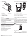 5
5
-
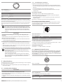 6
6
-
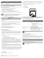 7
7
-
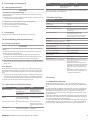 8
8
-
 9
9
-
 10
10
-
 11
11
-
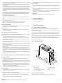 12
12
-
 13
13
-
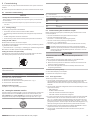 14
14
-
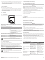 15
15
-
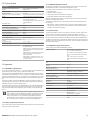 16
16
-
 17
17
-
 18
18
-
 19
19
-
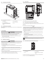 20
20
-
 21
21
-
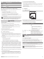 22
22
-
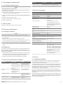 23
23
-
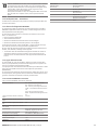 24
24
-
 25
25
-
 26
26
-
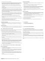 27
27
-
 28
28
-
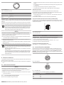 29
29
-
 30
30
-
 31
31
-
 32
32
-
 33
33
-
 34
34
-
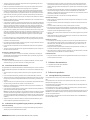 35
35
-
 36
36
-
 37
37
-
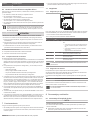 38
38
-
 39
39
-
 40
40
-
 41
41
-
 42
42
-
 43
43
-
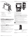 44
44
-
 45
45
-
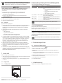 46
46
-
 47
47
-
 48
48
-
 49
49


Emerson R412013605-BAL-001-AD Användarmanual
- Typ
- Användarmanual
på andra språk
Andra dokument
-
AVENTICS R412013605 Användarmanual
-
-
AVENTICS DDL valve control, B-design, valve control unit Bruksanvisning
-
-
-
-
AVENTICS Bus Coupler AES/Valve Driver AV Ethernet POWERLINK Användarmanual
-
-
-